EP0768271A2 - Bobinoir pour un fil en déplacement continu - Google Patents
Bobinoir pour un fil en déplacement continu Download PDFInfo
- Publication number
- EP0768271A2 EP0768271A2 EP96116021A EP96116021A EP0768271A2 EP 0768271 A2 EP0768271 A2 EP 0768271A2 EP 96116021 A EP96116021 A EP 96116021A EP 96116021 A EP96116021 A EP 96116021A EP 0768271 A2 EP0768271 A2 EP 0768271A2
- Authority
- EP
- European Patent Office
- Prior art keywords
- drum
- winding
- contact roller
- thread
- speed
- Prior art date
- Legal status (The legal status is an assumption and is not a legal conclusion. Google has not performed a legal analysis and makes no representation as to the accuracy of the status listed.)
- Granted
Links
- 238000004804 winding Methods 0.000 title claims abstract description 108
- 238000000034 method Methods 0.000 claims abstract description 13
- 230000006870 function Effects 0.000 claims description 8
- 230000008569 process Effects 0.000 abstract description 6
- 230000015572 biosynthetic process Effects 0.000 abstract 1
- 230000008859 change Effects 0.000 description 6
- 230000007423 decrease Effects 0.000 description 5
- 230000001276 controlling effect Effects 0.000 description 4
- 238000011144 upstream manufacturing Methods 0.000 description 3
- 238000010586 diagram Methods 0.000 description 2
- 230000002093 peripheral effect Effects 0.000 description 2
- 230000001105 regulatory effect Effects 0.000 description 2
- 230000002411 adverse Effects 0.000 description 1
- 238000000418 atomic force spectrum Methods 0.000 description 1
- 230000008901 benefit Effects 0.000 description 1
- 230000033228 biological regulation Effects 0.000 description 1
- 230000005540 biological transmission Effects 0.000 description 1
- 238000010276 construction Methods 0.000 description 1
- 230000001419 dependent effect Effects 0.000 description 1
- 230000002349 favourable effect Effects 0.000 description 1
- 238000004519 manufacturing process Methods 0.000 description 1
- 230000005012 migration Effects 0.000 description 1
- 238000013508 migration Methods 0.000 description 1
- 238000009987 spinning Methods 0.000 description 1
- 238000003860 storage Methods 0.000 description 1
- 230000001960 triggered effect Effects 0.000 description 1
Images

Classifications
-
- B—PERFORMING OPERATIONS; TRANSPORTING
- B65—CONVEYING; PACKING; STORING; HANDLING THIN OR FILAMENTARY MATERIAL
- B65H—HANDLING THIN OR FILAMENTARY MATERIAL, e.g. SHEETS, WEBS, CABLES
- B65H61/00—Applications of devices for metering predetermined lengths of running material
- B65H61/005—Applications of devices for metering predetermined lengths of running material for measuring speed of running yarns
-
- B—PERFORMING OPERATIONS; TRANSPORTING
- B65—CONVEYING; PACKING; STORING; HANDLING THIN OR FILAMENTARY MATERIAL
- B65H—HANDLING THIN OR FILAMENTARY MATERIAL, e.g. SHEETS, WEBS, CABLES
- B65H54/00—Winding, coiling, or depositing filamentary material
- B65H54/02—Winding and traversing material on to reels, bobbins, tubes, or like package cores or formers
- B65H54/40—Arrangements for rotating packages
- B65H54/52—Drive contact pressure control, e.g. pressing arrangements
-
- B—PERFORMING OPERATIONS; TRANSPORTING
- B65—CONVEYING; PACKING; STORING; HANDLING THIN OR FILAMENTARY MATERIAL
- B65H—HANDLING THIN OR FILAMENTARY MATERIAL, e.g. SHEETS, WEBS, CABLES
- B65H67/00—Replacing or removing cores, receptacles, or completed packages at paying-out, winding, or depositing stations
- B65H67/04—Arrangements for removing completed take-up packages and or replacing by cores, formers, or empty receptacles at winding or depositing stations; Transferring material between adjacent full and empty take-up elements
- B65H67/044—Continuous winding apparatus for winding on two or more winding heads in succession
- B65H67/048—Continuous winding apparatus for winding on two or more winding heads in succession having winding heads arranged on rotary capstan head
-
- B—PERFORMING OPERATIONS; TRANSPORTING
- B65—CONVEYING; PACKING; STORING; HANDLING THIN OR FILAMENTARY MATERIAL
- B65H—HANDLING THIN OR FILAMENTARY MATERIAL, e.g. SHEETS, WEBS, CABLES
- B65H2511/00—Dimensions; Position; Numbers; Identification; Occurrences
- B65H2511/20—Location in space
- B65H2511/21—Angle
- B65H2511/212—Rotary position
-
- B—PERFORMING OPERATIONS; TRANSPORTING
- B65—CONVEYING; PACKING; STORING; HANDLING THIN OR FILAMENTARY MATERIAL
- B65H—HANDLING THIN OR FILAMENTARY MATERIAL, e.g. SHEETS, WEBS, CABLES
- B65H2513/00—Dynamic entities; Timing aspects
- B65H2513/10—Speed
- B65H2513/11—Speed angular
-
- B—PERFORMING OPERATIONS; TRANSPORTING
- B65—CONVEYING; PACKING; STORING; HANDLING THIN OR FILAMENTARY MATERIAL
- B65H—HANDLING THIN OR FILAMENTARY MATERIAL, e.g. SHEETS, WEBS, CABLES
- B65H2557/00—Means for control not provided for in groups B65H2551/00 - B65H2555/00
- B65H2557/20—Calculating means; Controlling methods
- B65H2557/24—Calculating methods; Mathematic models
-
- B—PERFORMING OPERATIONS; TRANSPORTING
- B65—CONVEYING; PACKING; STORING; HANDLING THIN OR FILAMENTARY MATERIAL
- B65H—HANDLING THIN OR FILAMENTARY MATERIAL, e.g. SHEETS, WEBS, CABLES
- B65H2557/00—Means for control not provided for in groups B65H2551/00 - B65H2555/00
- B65H2557/30—Control systems architecture or components, e.g. electronic or pneumatic modules; Details thereof
-
- B—PERFORMING OPERATIONS; TRANSPORTING
- B65—CONVEYING; PACKING; STORING; HANDLING THIN OR FILAMENTARY MATERIAL
- B65H—HANDLING THIN OR FILAMENTARY MATERIAL, e.g. SHEETS, WEBS, CABLES
- B65H2701/00—Handled material; Storage means
- B65H2701/30—Handled filamentary material
- B65H2701/31—Textiles threads or artificial strands of filaments
Definitions
- the invention relates to a winding machine for a continuously running thread, with a rotatable drum on which two drivable winding spindles are rotatably mounted, with a laying device and a contact roller, which are arranged upstream of the drum in the thread path, the contact roller being in circumferential contact with the spool, which forms on the winding spindle in operation, and the distance between the axis of the contact roller and the axis of the winding spindle in operation can be varied in the sense of an increase in accordance with the growing diameter of the coil.
- a method for regulating a winding machine for a continuously running thread in which a drum on which two drivable winding spindles are rotatably mounted are rotated relative to a contact roller and the thread is wound onto the bobbin with a laying device via the contact roller, the distance between the axis of the contact roller and the axis of the winding spindle in operation being changed in the sense of an enlargement in accordance with the growing diameter of the bobbin .
- a winding machine of this type is known from EP 0 374 536 B1.
- the contact roller used here can be pivoted on a rocker arm or can be moved in a straight line in a straight guide.
- a sensor is provided which detects the movement of the contact roller relative to the surface of the bobbin forming on the winding spindle in operation.
- the sensor belongs to a control device and works as a two-point control element. If the contact roller is moved by the diameter of the bobbin, which increases during the winding process, with the axis of the drum at a standstill, then a control pulse is applied to the rotary drive of the drum and the drum is rotated, so that the direction of movement of the contact roller is reversed and this falls below the set trigger point on the control element.
- the number of readjustment steps per unit of time decreases due to the migration of the bobbin while the drum is rotating and the increasingly slow growing bobbin diameter, ie the change in the contact pressure via the contact roller slows down.
- Another disadvantage is that a separate complex control device is required for control.
- the invention has for its object to provide a further winding machine of the type described above, which is inexpensive to manufacture and easy to maintain and also has a small size.
- a control device is provided for the rotation of the drum, that the winding machine has a device for determining the speed of the thread and a device for determining the speed of the winding spindle in operation, and that the control device has a computing unit for calculating the respective current diameter of the bobbin forming on the operating bobbin and the respective current angular velocity between the beginning and end of each computing cycle as control variables for the rotation of the drum over the entire winding cycle.
- the invention is based on the idea of first providing a regulating device instead of the known control device in order to regulate the rotation of the drum in a quasi-constant movement sequence.
- This can be designed so that, for. B. runs every 10 ms a computing cycle, each followed by a control cycle. This creates a quasi-continuous movement of the drum during the winding cycle.
- the winding machine does not require any additional elements, such as sensors or the like, for the regulation, but rather already existing elements which are necessary for the control of the Thread tension on the winding machine are used.
- a device for determining the speed of the thread and a device for determining the speed of the winding spindle in operation are used.
- the current diameter of the bobbin being formed is calculated from the thread speed and the speed of the winding spindle in operation, and the respective current angular velocity between the beginning and the end of each computing cycle is determined.
- the drum is rotated further at this current angular velocity.
- a respective setpoint of the angle of rotation for the drum is determined from the calculation of the respective current diameter.
- the current angular velocity at which the drum is rotated is calculated from the measured period of time that has elapsed between the beginning and the end of each computing cycle and the respective target value of the angle of rotation.
- the setpoint of the angle of rotation is the angle between the axis of the winding spindle at the beginning and at the end of a respective calculation cycle above the axis of the drum.
- the advantage here is that no additional sensors are required, but existing sensors are used for thread tension control.
- the control device is no longer dependent on a movement of the contact roller, ie the contact roller can be designed and arranged completely freely.
- the contact roller it is possible to use the contact roller to exert such a contact pressure on the circumference of the coil that is formed, which is designed according to criteria that are independent of the control system, for example, it has a continuous course.
- a constant decrease in the contact pressure is possible without fluctuations, which has a favorable effect on the coil structure.
- a microprocessor can be provided as the computing unit.
- Such a microprocessor represents a suitable structural unit for the implementation of the computing unit various desired arithmetic operations and steps can be summarized, as they are also required for thread tension control.
- the device for determining the speed of the thread can have a device for detecting the speed of the contact roller. Since the diameter of the contact roller and the run-up angle at which the thread is placed obliquely on the circumference of the contact roller are known, the speed of the thread can be calculated in a simple manner. However, any other device for determining the speed of the thread can also be used, for example a separate device which is arranged upstream of the laying device or at another location.
- the device for determining the speed of the thread and the device for determining the speed of the winding spindle in operation are also designed as control devices for the rotation of the drum. This means that existing elements are used anyway.
- the contact roller can be mounted so that it can be deflected relative to the axis of the drum and thus to the respective winding spindle, a device for controlling a constant or controlled variable contact pressure of the contact roller on the winding spindle in operation being provided.
- the avoidable mounting of the contact roller makes sense on the one hand, in order to be able to turn the drum with the two winding spindles.
- the contact roller does not necessarily have to move, movement of the contact roller can nevertheless be provided, but this then serves another purpose, namely the application of a contact pressure or a contact force curve via the winding cycle.
- the computing unit can have a memory for receiving a table of values for the setpoint of the rotation angle of the drum as a function of the diameter of the coil. It goes without saying that such a value table can be entered depending on the application. However, it is also possible to design the arithmetic unit so that the setpoint of the angle of rotation is calculated as a function of the diameter of the coil. The computing cycle will then take a little longer. In view of the mechanically moving parts of the winding machine, however, this has no disadvantageous consequences.
- the method for controlling a winding machine is characterized in that the drum is rotated continuously with angular speeds changing from computing cycle to computing cycle.
- the invention is based on the idea of leaving the rotating and stopping of the drum alternately, as is known in the prior art, and changing it into an uninterrupted, continuous rotation of the drum.
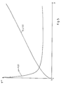
- Changing angular velocities are used in succession, ie the angular velocity of the rotary drive of the drum is switched to another angular velocity, so that the drum definitely performs a continuous movement, the course of the changing angular velocities having a hyperbolic character.
- the current angular velocities used decrease during a winding trip.
- slightly increasing angular velocities can also result at the end of a winding trip. In this area, however, the change in angular velocity from control cycle to control cycle is not particularly great.
- Computation cycles can advantageously be used which are repeated at time intervals constant over the winding cycle, for example in particular in 10 msec. It is perfectly possible to repeat the calculation cycles at such short intervals. However, it is not harmful if the number of computing cycles is reduced and the time intervals are increased, since the drive of the drum anyway contains a large number of mechanical elements which prove to be comparatively slow. It is also possible to use different numbers of computing cycles on the one hand and control cycles on the other hand, to form averages or the like. In general, however, this is not necessary.
- a method is possible in which the current angular velocity of the rotation of the drum changes for each control cycle as a function of a constant increase in the diameter of the coil.
- the diameter of the bobbin will grow comparatively less quickly than at the beginning of a winding cycle.
- the angular velocities will change significantly more at the beginning of a winding trip than at the end of a winding trip.
- the setpoint value of the angle of rotation over the winding travel remains constant, in particular in the central region of the winding travel, over a larger area.
- the respective current angular velocity of the rotation of the drum is calculated from the previous control cycle. Although this is a small error, this can easily be accepted because the required accuracy is achieved by the large number of computing and control cycles.
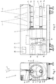
- a thread 1 is shown, which runs continuously in the direction of an arrow 2 from a spinning shaft to a winding machine 3.
- the thread runs over a laying device 4 on the circumference of a contact roller 5.
- a drum 6 is rotatably or pivotably mounted about its axis 7 according to arrow 8.
- two winding spindles 9 and 10 are rotatably mounted.
- the axes 11 and 12 of the winding spindles 9 and 10 are vertically aligned below the axis 13 of the contact roller 5.
- An empty tube 14 is located on the winding spindle 9.
- This winding spindle 9 is shown in the working position, that is to say at the beginning of a winding process or a winding cycle.
- the winding spindle 10 with a coil 15 wound thereon is in the reserve position in which the bobbin change is carried out.
- the winding machine 3 is designed so that two threads 1 are wound on two spools 15 simultaneously.
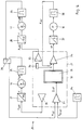
- the winding machine 3 has a motor 16 for driving the winding spindle 9 in the working position and in the reserve position.
- a motor 17 is for driving the winding spindle 10 in the reserve position and the working position intended.
- a motor 18 serves to drive the drum 6.
- a gear 19 serves to transmit the rotary drive of the two motors 16 and 17 to the winding spindles 9 and 10 despite their pivotability over the drum 6.
- the winding machine 3 has a schematically illustrated control device 20.
- a computing unit 21, for example in the form of a microprocessor, can be part of the control device 20.
- FIG 3 illustrates once again the relative positions during a winding trip.
- the winding spindle 9 is shown with its axis 11 and the empty sleeve 14 at the beginning of the winding process.
- the circumference of the contact roller 5 lies against the circumference of the sleeve 14.
- the drum 6 is rotated according to arrow 8, so that the winding spindle 9, on which the bobbin 15 forms, evades in the clockwise direction.
- the pivoting or rotation of the drum 6 takes place over a rotation angle 22.
- the winding spindle 10 rotates with the drum 6 in the same direction of rotation.
- the angle of rotation 22 increases as the diameter of the bobbin 15 increases.
- the angle of rotation 22 is the angle that is spanned between the axis 11 of the winding spindle 9 in operation at the beginning of the winding process and almost at the end of a winding cycle above the fixed axis 7 of the drum 6 . It can thus be seen that a certain rotation angle 22 belongs to a certain diameter 23 of the winding spindle 15. It can also be seen from FIG. 3 that the circumference of the contact roller 5 always lies against the circumference of the coil 15 that is being formed, but the contact point changes. This change depends on the geometric relationships of the arrangement of the parts to one another.
- the contact point can initially move so that the wrap angle with which the thread 1 wraps around the circumference of the contact roller 5 initially decreases, but increases somewhat towards the end of a winding trip.
- the contact roller 5 can be mounted so as to be avoidable relative to the axis 7 of the drum 6 by means of a bearing (not shown). It is also possible to get one To provide a device for controlling a constant or controlled variable contact pressure of the contact roller on the circumference of the coil 15, which forms the winding spindle located on its operation.
- a sensor 24 is used to detect the speed of the contact roller 5.
- a sensor 25 is used to detect the speed of the winding spindle 9.
- a sensor 26 detects the speed of the winding spindle 10.
- a frequency converter 27 is assigned to the motor 16 for driving the winding spindle 9. Accordingly, a frequency converter 28 is provided in the drive of the winding spindle 10.
- An OR element 29 serves to change the working position or reserve position between the two winding spindles 9 and 10.
- An index "is” denotes a variable in its current value.
- An index "target” identifies a calculated target value.
- a difference value is designated by DELTA.
- FIG. 5 shows the course of the angle of rotation phi of the drum 6 as a function of the increase in diameter of the coil 15 over the diameter D or also over time. The course of the angular velocity over time is also shown. This curve is hyperbolic in character.
- a value table 33 is stored in the memory 32 of the computing unit 21.
- the growing diameters 23 of the coil 15 (for example in coil growth rates of 2 mm each) are assigned certain angles of rotation 22 (phi soll ).
- the time 36 is measured, which takes a coil diameter increase of z. B. 2 mm leads.
- the current diameter 23 (D) of the coil 15 is calculated from the speed n K of the contact roller and the speed n S of the coil 15 or the winding spindle 9, which is currently in the working position.
- the drum 6 is rotated further until the next DELTA D spool increase is reached.
- the angle of rotation phi ist achieved in this case supplied by the resolver 38 of the motor 18 of the drum, is fed back as the actual value to the I controller 34 of the computing unit 21 and compared with the target value phi soll from the stored value table 33.
- the angular velocity omega of the I controller 34 is corrected to the control device 20 by iterative approximation, so that the deviation between phi and phi is intended in the course of the winding cycle is always smaller.
- control device 20 without storing a table of values:
- the current diameter 23 of the coil 15 (D) is, as above, calculated from the speed n K of the contact roller 5 and the speed n S of the winding spindle 9 or 10 with the coil 15.
- omega f (phi should , T)
- the drum 6 stands still until the start of the second calculation cycle. With the calculated angular velocity omega (> 0), the drum 6 is rotated further until the next calculation cycle gives a new value for the angular velocity omega.
- the actual value of the rotation angle phi is supplied by the resolver 38 of the motor 18 of the drum 6, are compared.
- the angular velocity omega of the I controller 34 is corrected to the control device 20 by iterative approximation, so that the deviation between phi and phi is intended in the course of the winding cycle is always smaller.
Landscapes
- Engineering & Computer Science (AREA)
- Textile Engineering (AREA)
- Winding Filamentary Materials (AREA)
- Spinning Methods And Devices For Manufacturing Artificial Fibers (AREA)
- Tension Adjustment In Filamentary Materials (AREA)
- Yarns And Mechanical Finishing Of Yarns Or Ropes (AREA)
- Controlling Rewinding, Feeding, Winding, Or Abnormalities Of Webs (AREA)
- Replacement Of Web Rolls (AREA)
Applications Claiming Priority (2)
| Application Number | Priority Date | Filing Date | Title |
|---|---|---|---|
| DE19538480 | 1995-10-16 | ||
| DE19538480A DE19538480C2 (de) | 1995-10-16 | 1995-10-16 | Spulmaschine und Verfahren zum Aufwickeln eines kontinuierlich zulaufenden Fadens auf eine Spule |
Publications (3)
| Publication Number | Publication Date |
|---|---|
| EP0768271A2 true EP0768271A2 (fr) | 1997-04-16 |
| EP0768271A3 EP0768271A3 (fr) | 1998-01-21 |
| EP0768271B1 EP0768271B1 (fr) | 2000-02-09 |
Family
ID=7774980
Family Applications (1)
| Application Number | Title | Priority Date | Filing Date |
|---|---|---|---|
| EP96116021A Expired - Lifetime EP0768271B1 (fr) | 1995-10-16 | 1996-10-07 | Bobinoir pour un fil en déplacement continu |
Country Status (7)
| Country | Link |
|---|---|
| US (1) | US5785265A (fr) |
| EP (1) | EP0768271B1 (fr) |
| JP (1) | JP3523429B2 (fr) |
| KR (1) | KR970020917A (fr) |
| AT (1) | ATE189666T1 (fr) |
| DE (2) | DE19538480C2 (fr) |
| TW (1) | TW316892B (fr) |
Cited By (5)
| Publication number | Priority date | Publication date | Assignee | Title |
|---|---|---|---|---|
| KR970020917A (ko) * | 1995-10-16 | 1997-05-28 | 베르너 리베르크네흐트 | 연속공급사의 권취기 |
| WO1998042607A1 (fr) * | 1997-03-25 | 1998-10-01 | Barmag Ag | Procede d'embobinage d'un fil arrivant en continu |
| EP0905077A2 (fr) * | 1997-09-30 | 1999-03-31 | Georg Sahm Gmbh & Co. Kg | Machine et procédé de bobinage pour un fil en déplacement continu |
| EP1118569A2 (fr) * | 1999-12-17 | 2001-07-25 | COGNETEX S.r.l. | Procédé pour la commande de l'entraínement en rotation de la tourelle d'un dispositif enrouleur de fil |
| DE10151310A1 (de) * | 2001-10-17 | 2003-05-08 | Barmag Spinnzwirn Gmbh | Aufspulvorrichtung |
Families Citing this family (11)
| Publication number | Priority date | Publication date | Assignee | Title |
|---|---|---|---|---|
| DE19832809A1 (de) * | 1997-07-26 | 1999-01-28 | Barmag Barmer Maschf | Verfahren zur Steuerung einer Aufspulmaschine |
| DE19802509A1 (de) * | 1998-01-23 | 1999-07-29 | Rieter Ag Maschf | Aufwindevorrichtung für Endlosfäden |
| KR100274057B1 (ko) * | 1998-03-07 | 2001-12-17 | 홍영철 | 와이어다단권취장치 |
| DE29908962U1 (de) | 1999-05-21 | 1999-09-02 | Neumag - Neumünstersche Maschinen- und Anlagenbau GmbH, 24536 Neumünster | Aufspulmaschine |
| KR100430760B1 (ko) * | 2001-07-25 | 2004-05-10 | (주)누리 이엔지 | 복수 스핀들 구동형 권선기 제어시스템 및 이를 이용한 제어방법 |
| DE10207900A1 (de) * | 2002-02-21 | 2003-09-25 | Sahm Georg Fa | Spulmaschine und Verfahren zum Aufwickeln eines kontinuierlich zulaufenden Fadens auf eine Spule |
| DE10253253A1 (de) * | 2002-11-15 | 2004-06-09 | Georg Sahm Gmbh & Co. Kg | Spulmaschine und Verfahren zum Aufwickeln eines kontinuierlich zulaufenden Fadens auf eine Spule |
| FR2850093B1 (fr) * | 2003-01-22 | 2005-12-30 | Saint Gobain Vetrotex | Bobinoir a courses decouplees pour fibres thermoplastiques |
| KR100657782B1 (ko) * | 2006-01-25 | 2006-12-14 | (재)한국섬유기계연구소 | 권사기의 권취량 측정장치 |
| CN106044362B (zh) * | 2016-08-15 | 2019-04-12 | 浙江万方安道拓纺织科技有限公司 | 一种纱线绕线机 |
| DE102022002512A1 (de) * | 2022-07-09 | 2024-01-11 | Oerlikon Textile Gmbh & Co. Kg | Verfahren und Vorrichtung zum Ermitteln einer Drehzahlstellgröße für eine Antriebseinheit eines Spulspindelrevolvers |
Citations (6)
| Publication number | Priority date | Publication date | Assignee | Title |
|---|---|---|---|---|
| DE3810365A1 (de) * | 1988-03-26 | 1989-10-05 | Schlafhorst & Co W | Verfahren und vorrichtung zum ermitteln des spulenumfangs von kreuzspulen und zum verwerten des ergebnisses |
| DE3911854A1 (de) * | 1988-04-11 | 1989-11-09 | Murata Machinery Ltd | Auflagedruck-steuervorrichtung fuer eine spulmaschine |
| EP0374536B1 (fr) * | 1988-12-22 | 1994-03-30 | B a r m a g AG | Machine de bobinage |
| US5407143A (en) * | 1992-03-02 | 1995-04-18 | Kamitsu Seisakusho Ltd. | Turret type yarn winder |
| DE4423491A1 (de) * | 1994-07-05 | 1996-01-11 | Neumag Gmbh | Verfahren zum Steuern des Drehantriebs einer Aufspulmaschine |
| JPH08290870A (ja) * | 1995-04-24 | 1996-11-05 | Murata Mach Ltd | 巻取機のボビン位置調整方法及びその装置 |
Family Cites Families (14)
| Publication number | Priority date | Publication date | Assignee | Title |
|---|---|---|---|---|
| JPS5153040A (en) * | 1974-11-06 | 1976-05-11 | Teijin Ltd | Shijono kosokumakitori hoho oyobi sochi |
| CH618401A5 (fr) * | 1975-06-12 | 1980-07-31 | Barmag Barmer Maschf | |
| JPS5878953A (ja) * | 1981-11-04 | 1983-05-12 | Teijin Ltd | 糸条巻取装置 |
| JPS59227663A (ja) * | 1983-06-07 | 1984-12-20 | Teijin Ltd | タ−レツト式自動巻取機の糸条切替方法および装置 |
| JPS612677A (ja) * | 1984-06-14 | 1986-01-08 | Teijin Ltd | スピンドルドライブ式の自動巻取機における糸条切替方法 |
| DE3673236D1 (de) * | 1985-05-17 | 1990-09-13 | Teijin Seiki Co Ltd | Garnwickelmaschine mit spindelantrieb. |
| US5100072A (en) * | 1990-06-06 | 1992-03-31 | Barmag Ag | Yarn winding apparatus and method |
| US5141169A (en) * | 1990-08-06 | 1992-08-25 | Teijin Seiki Co., Ltd. | Method and apparatus for winding a yarn according to desired tension and winding speed |
| DE4208393A1 (de) * | 1992-03-16 | 1993-09-23 | Sahm Georg Fa | Verfahren zum aufspulen kontinuierlich mit vorzugsweise konstanter geschwindigkeit einer spuleinrichtung zugefuehrtem, fadenfoermigem spulgut in gestufter praezisionskreuzwicklung sowie spuleinrichtung zur durchfuehrung des verfahrens |
| US5193598A (en) * | 1992-06-23 | 1993-03-16 | Estrem Jim J | Portable support stand attachable to a sawhorse |
| EP0580548A1 (fr) * | 1992-07-23 | 1994-01-26 | Maschinenfabrik Rieter Ag | Procédé et dispositif pour le bobinage d'un fil |
| JP3224928B2 (ja) * | 1993-01-14 | 2001-11-05 | 帝人製機株式会社 | 糸条の巻取機 |
| JP3211541B2 (ja) * | 1994-02-24 | 2001-09-25 | 村田機械株式会社 | 紡糸巻取機及びそのボビン位置制御方法 |
| DE19538480C2 (de) * | 1995-10-16 | 2001-10-25 | Sahm Georg Fa | Spulmaschine und Verfahren zum Aufwickeln eines kontinuierlich zulaufenden Fadens auf eine Spule |
-
1995
- 1995-10-16 DE DE19538480A patent/DE19538480C2/de not_active Expired - Fee Related
-
1996
- 1996-10-07 EP EP96116021A patent/EP0768271B1/fr not_active Expired - Lifetime
- 1996-10-07 AT AT96116021T patent/ATE189666T1/de not_active IP Right Cessation
- 1996-10-07 DE DE59604407T patent/DE59604407D1/de not_active Expired - Fee Related
- 1996-10-09 TW TW085112332A patent/TW316892B/zh active
- 1996-10-15 US US08/732,551 patent/US5785265A/en not_active Expired - Fee Related
- 1996-10-15 JP JP27239896A patent/JP3523429B2/ja not_active Expired - Fee Related
- 1996-10-16 KR KR1019960046150A patent/KR970020917A/ko active IP Right Grant
Patent Citations (6)
| Publication number | Priority date | Publication date | Assignee | Title |
|---|---|---|---|---|
| DE3810365A1 (de) * | 1988-03-26 | 1989-10-05 | Schlafhorst & Co W | Verfahren und vorrichtung zum ermitteln des spulenumfangs von kreuzspulen und zum verwerten des ergebnisses |
| DE3911854A1 (de) * | 1988-04-11 | 1989-11-09 | Murata Machinery Ltd | Auflagedruck-steuervorrichtung fuer eine spulmaschine |
| EP0374536B1 (fr) * | 1988-12-22 | 1994-03-30 | B a r m a g AG | Machine de bobinage |
| US5407143A (en) * | 1992-03-02 | 1995-04-18 | Kamitsu Seisakusho Ltd. | Turret type yarn winder |
| DE4423491A1 (de) * | 1994-07-05 | 1996-01-11 | Neumag Gmbh | Verfahren zum Steuern des Drehantriebs einer Aufspulmaschine |
| JPH08290870A (ja) * | 1995-04-24 | 1996-11-05 | Murata Mach Ltd | 巻取機のボビン位置調整方法及びその装置 |
Non-Patent Citations (1)
| Title |
|---|
| PATENT ABSTRACTS OF JAPAN vol. 097, no. 003, 31.März 1997 & JP 08 290870 A (MURATA MACH LTD), 5.November 1996, * |
Cited By (8)
| Publication number | Priority date | Publication date | Assignee | Title |
|---|---|---|---|---|
| KR970020917A (ko) * | 1995-10-16 | 1997-05-28 | 베르너 리베르크네흐트 | 연속공급사의 권취기 |
| WO1998042607A1 (fr) * | 1997-03-25 | 1998-10-01 | Barmag Ag | Procede d'embobinage d'un fil arrivant en continu |
| US6105896A (en) * | 1997-03-25 | 2000-08-22 | Barmag Ag | Method and apparatus for winding an advancing yarn |
| EP0905077A2 (fr) * | 1997-09-30 | 1999-03-31 | Georg Sahm Gmbh & Co. Kg | Machine et procédé de bobinage pour un fil en déplacement continu |
| EP0905077A3 (fr) * | 1997-09-30 | 2000-09-13 | Georg Sahm Gmbh & Co. Kg | Machine et procédé de bobinage pour un fil en déplacement continu |
| EP1118569A2 (fr) * | 1999-12-17 | 2001-07-25 | COGNETEX S.r.l. | Procédé pour la commande de l'entraínement en rotation de la tourelle d'un dispositif enrouleur de fil |
| EP1118569A3 (fr) * | 1999-12-17 | 2001-11-14 | COGNETEX S.r.l. | Procédé pour la commande de l'entraínement en rotation de la tourelle d'un dispositif enrouleur de fil |
| DE10151310A1 (de) * | 2001-10-17 | 2003-05-08 | Barmag Spinnzwirn Gmbh | Aufspulvorrichtung |
Also Published As
| Publication number | Publication date |
|---|---|
| DE19538480C2 (de) | 2001-10-25 |
| JP3523429B2 (ja) | 2004-04-26 |
| DE59604407D1 (de) | 2000-03-16 |
| EP0768271B1 (fr) | 2000-02-09 |
| TW316892B (fr) | 1997-10-01 |
| EP0768271A3 (fr) | 1998-01-21 |
| US5785265A (en) | 1998-07-28 |
| JPH09169469A (ja) | 1997-06-30 |
| KR970020917A (ko) | 1997-05-28 |
| DE19538480C1 (de) | 1997-05-07 |
| ATE189666T1 (de) | 2000-02-15 |
Similar Documents
| Publication | Publication Date | Title |
|---|---|---|
| EP0768271B1 (fr) | Bobinoir pour un fil en déplacement continu | |
| DE2649780C3 (de) | Wickelmaschine fUr Textilgarne | |
| EP0914287B1 (fr) | Procede d'embobinage d'un fil arrivant en continu | |
| DE69413315T2 (de) | Verfahren und Vorrichtung zur Fadenverlegung auf einer Spule mit einer genuteten Antriebswalze | |
| EP0195325B1 (fr) | Procédé de bobinage | |
| DE2600511A1 (de) | Aufspulvorrichtung fuer draht | |
| EP0194524A2 (fr) | Procédé de bobinage | |
| DE69023235T2 (de) | Verfahren und Vorrichtung zum Aufspulen eines Garnes. | |
| DE10223484B4 (de) | Verfahren und Spulmaschine zum Aufwickeln eines kontinuierlich zulaufenden Fadens auf eine Hülse zu einer Spule | |
| EP0950627A1 (fr) | Procédé et dispositif pour enrouler sur une bobine un fil fourni à vitesse constante | |
| DE69402333T2 (de) | Spulmaschine für Faden | |
| EP0399243B1 (fr) | Procédé et dispositif pour éviter l'enroulage en ruban lors du bobinage d'une bobine croisée | |
| WO1999024344A1 (fr) | Procede et dispositif pour bobiner un fil defilant en continu | |
| DE2534239C2 (de) | Verfahren und Vorrichtung zur Bildstörung an einer Kreuzspuleinrichtung | |
| DE3035880A1 (de) | Vorrichtung und verfahren zum wickeln von garn von einem vorrat zu einem garnkoerper | |
| DE69114151T2 (de) | Apparat zum Aufwickeln von Spulen aus mehrsträngigen Kabeln. | |
| CH659261A5 (de) | Zwirnmaschine, insbesondere zum zwirnen von glasfaeden. | |
| DE19849007A1 (de) | Verfahren zum Aufspulen eines laufenden Fadens | |
| DE3906474A1 (de) | Verfahren und vorrichtung zum aufwickeln von vorbestimmten garnlaengen in lagen auf einer spule | |
| DE19832811A1 (de) | Verfahren zum Aufwickeln eines Fadens | |
| DE2345720A1 (de) | Verfahren und vorrichtung zum herstellen von litze | |
| DE10253253A1 (de) | Spulmaschine und Verfahren zum Aufwickeln eines kontinuierlich zulaufenden Fadens auf eine Spule | |
| EP1342688B1 (fr) | Procédé et dispositif pour bobiner un fil sur une machine pour fabriquer des bobines à spires croisées | |
| CH656739A5 (de) | Selbsttaetig arbeitende isolierband-wickelvorrichtung. | |
| DE1902722B2 (de) | Wickelmaschine zum Aufwickeln von strangförmigem Wickelgut auf eine Trommel |
Legal Events
| Date | Code | Title | Description |
|---|---|---|---|
| PUAI | Public reference made under article 153(3) epc to a published international application that has entered the european phase |
Free format text: ORIGINAL CODE: 0009012 |
|
| AK | Designated contracting states |
Kind code of ref document: A2 Designated state(s): AT CH DE FR GB IT LI |
|
| PUAL | Search report despatched |
Free format text: ORIGINAL CODE: 0009013 |
|
| AK | Designated contracting states |
Kind code of ref document: A3 Designated state(s): AT CH DE FR GB IT LI |
|
| 17P | Request for examination filed |
Effective date: 19980129 |
|
| 17Q | First examination report despatched |
Effective date: 19980807 |
|
| GRAG | Despatch of communication of intention to grant |
Free format text: ORIGINAL CODE: EPIDOS AGRA |
|
| GRAG | Despatch of communication of intention to grant |
Free format text: ORIGINAL CODE: EPIDOS AGRA |
|
| GRAH | Despatch of communication of intention to grant a patent |
Free format text: ORIGINAL CODE: EPIDOS IGRA |
|
| GRAH | Despatch of communication of intention to grant a patent |
Free format text: ORIGINAL CODE: EPIDOS IGRA |
|
| ITF | It: translation for a ep patent filed | ||
| GRAA | (expected) grant |
Free format text: ORIGINAL CODE: 0009210 |
|
| AK | Designated contracting states |
Kind code of ref document: B1 Designated state(s): AT CH DE FR GB IT LI |
|
| REF | Corresponds to: |
Ref document number: 189666 Country of ref document: AT Date of ref document: 20000215 Kind code of ref document: T |
|
| REG | Reference to a national code |
Ref country code: CH Ref legal event code: NV Representative=s name: RIEDERER HASLER & PARTNER PATENTANWAELTE AG Ref country code: CH Ref legal event code: EP |
|
| GBT | Gb: translation of ep patent filed (gb section 77(6)(a)/1977) |
Effective date: 20000209 |
|
| REF | Corresponds to: |
Ref document number: 59604407 Country of ref document: DE Date of ref document: 20000316 |
|
| ET | Fr: translation filed | ||
| GBT | Gb: translation of ep patent filed (gb section 77(6)(a)/1977) |
Free format text: ERRATUM: THE FOLLOWING EUROPEAN PATENTS WERE ADVERTISED IN ERROR IN JOURNAL 5781 DATED 1 MARCH 2000 AS HAVING BEEN FILED UNDER SECTION 77(6)(A) ON 8 FEBRUARY 2000. |
|
| PLBE | No opposition filed within time limit |
Free format text: ORIGINAL CODE: 0009261 |
|
| STAA | Information on the status of an ep patent application or granted ep patent |
Free format text: STATUS: NO OPPOSITION FILED WITHIN TIME LIMIT |
|
| 26N | No opposition filed | ||
| REG | Reference to a national code |
Ref country code: GB Ref legal event code: IF02 |
|
| PGFP | Annual fee paid to national office [announced via postgrant information from national office to epo] |
Ref country code: DE Payment date: 20030808 Year of fee payment: 8 |
|
| PGFP | Annual fee paid to national office [announced via postgrant information from national office to epo] |
Ref country code: GB Payment date: 20030915 Year of fee payment: 8 |
|
| PGFP | Annual fee paid to national office [announced via postgrant information from national office to epo] |
Ref country code: FR Payment date: 20031021 Year of fee payment: 8 |
|
| PGFP | Annual fee paid to national office [announced via postgrant information from national office to epo] |
Ref country code: AT Payment date: 20031024 Year of fee payment: 8 |
|
| PGFP | Annual fee paid to national office [announced via postgrant information from national office to epo] |
Ref country code: CH Payment date: 20031027 Year of fee payment: 8 |
|
| PG25 | Lapsed in a contracting state [announced via postgrant information from national office to epo] |
Ref country code: GB Free format text: LAPSE BECAUSE OF NON-PAYMENT OF DUE FEES Effective date: 20041007 Ref country code: AT Free format text: LAPSE BECAUSE OF NON-PAYMENT OF DUE FEES Effective date: 20041007 |
|
| PG25 | Lapsed in a contracting state [announced via postgrant information from national office to epo] |
Ref country code: LI Free format text: LAPSE BECAUSE OF NON-PAYMENT OF DUE FEES Effective date: 20041031 Ref country code: CH Free format text: LAPSE BECAUSE OF NON-PAYMENT OF DUE FEES Effective date: 20041031 |
|
| PG25 | Lapsed in a contracting state [announced via postgrant information from national office to epo] |
Ref country code: DE Free format text: LAPSE BECAUSE OF NON-PAYMENT OF DUE FEES Effective date: 20050503 |
|
| GBPC | Gb: european patent ceased through non-payment of renewal fee |
Effective date: 20041007 |
|
| REG | Reference to a national code |
Ref country code: CH Ref legal event code: PL |
|
| PG25 | Lapsed in a contracting state [announced via postgrant information from national office to epo] |
Ref country code: FR Free format text: LAPSE BECAUSE OF NON-PAYMENT OF DUE FEES Effective date: 20050630 |
|
| REG | Reference to a national code |
Ref country code: FR Ref legal event code: ST |
|
| PG25 | Lapsed in a contracting state [announced via postgrant information from national office to epo] |
Ref country code: IT Free format text: LAPSE BECAUSE OF NON-PAYMENT OF DUE FEES;WARNING: LAPSES OF ITALIAN PATENTS WITH EFFECTIVE DATE BEFORE 2007 MAY HAVE OCCURRED AT ANY TIME BEFORE 2007. THE CORRECT EFFECTIVE DATE MAY BE DIFFERENT FROM THE ONE RECORDED. Effective date: 20051007 |