EP0767006A1 - Méthode et dispositif d'alimentation en poudre d'un appareil de revêtement à poudre - Google Patents
Méthode et dispositif d'alimentation en poudre d'un appareil de revêtement à poudre Download PDFInfo
- Publication number
- EP0767006A1 EP0767006A1 EP96115512A EP96115512A EP0767006A1 EP 0767006 A1 EP0767006 A1 EP 0767006A1 EP 96115512 A EP96115512 A EP 96115512A EP 96115512 A EP96115512 A EP 96115512A EP 0767006 A1 EP0767006 A1 EP 0767006A1
- Authority
- EP
- European Patent Office
- Prior art keywords
- powder
- chamber
- nozzle
- air
- fluidized
- Prior art date
- Legal status (The legal status is an assumption and is not a legal conclusion. Google has not performed a legal analysis and makes no representation as to the accuracy of the status listed.)
- Granted
Links
Images


Classifications
-
- B—PERFORMING OPERATIONS; TRANSPORTING
- B05—SPRAYING OR ATOMISING IN GENERAL; APPLYING FLUENT MATERIALS TO SURFACES, IN GENERAL
- B05B—SPRAYING APPARATUS; ATOMISING APPARATUS; NOZZLES
- B05B5/00—Electrostatic spraying apparatus; Spraying apparatus with means for charging the spray electrically; Apparatus for spraying liquids or other fluent materials by other electric means
- B05B5/025—Discharge apparatus, e.g. electrostatic spray guns
- B05B5/03—Discharge apparatus, e.g. electrostatic spray guns characterised by the use of gas, e.g. electrostatically assisted pneumatic spraying
- B05B5/032—Discharge apparatus, e.g. electrostatic spray guns characterised by the use of gas, e.g. electrostatically assisted pneumatic spraying for spraying particulate materials
-
- B—PERFORMING OPERATIONS; TRANSPORTING
- B05—SPRAYING OR ATOMISING IN GENERAL; APPLYING FLUENT MATERIALS TO SURFACES, IN GENERAL
- B05B—SPRAYING APPARATUS; ATOMISING APPARATUS; NOZZLES
- B05B1/00—Nozzles, spray heads or other outlets, with or without auxiliary devices such as valves, heating means
- B05B1/14—Nozzles, spray heads or other outlets, with or without auxiliary devices such as valves, heating means with multiple outlet openings; with strainers in or outside the outlet opening
- B05B1/16—Nozzles, spray heads or other outlets, with or without auxiliary devices such as valves, heating means with multiple outlet openings; with strainers in or outside the outlet opening having selectively- effective outlets
- B05B1/1627—Nozzles, spray heads or other outlets, with or without auxiliary devices such as valves, heating means with multiple outlet openings; with strainers in or outside the outlet opening having selectively- effective outlets with a selecting mechanism comprising a gate valve, a sliding valve or a cock
- B05B1/1636—Nozzles, spray heads or other outlets, with or without auxiliary devices such as valves, heating means with multiple outlet openings; with strainers in or outside the outlet opening having selectively- effective outlets with a selecting mechanism comprising a gate valve, a sliding valve or a cock by relative rotative movement of the valve elements
- B05B1/1645—Nozzles, spray heads or other outlets, with or without auxiliary devices such as valves, heating means with multiple outlet openings; with strainers in or outside the outlet opening having selectively- effective outlets with a selecting mechanism comprising a gate valve, a sliding valve or a cock by relative rotative movement of the valve elements the outlets being rotated during selection
- B05B1/1654—Nozzles, spray heads or other outlets, with or without auxiliary devices such as valves, heating means with multiple outlet openings; with strainers in or outside the outlet opening having selectively- effective outlets with a selecting mechanism comprising a gate valve, a sliding valve or a cock by relative rotative movement of the valve elements the outlets being rotated during selection about an axis parallel to the liquid passage in the stationary valve element
-
- B—PERFORMING OPERATIONS; TRANSPORTING
- B05—SPRAYING OR ATOMISING IN GENERAL; APPLYING FLUENT MATERIALS TO SURFACES, IN GENERAL
- B05B—SPRAYING APPARATUS; ATOMISING APPARATUS; NOZZLES
- B05B5/00—Electrostatic spraying apparatus; Spraying apparatus with means for charging the spray electrically; Apparatus for spraying liquids or other fluent materials by other electric means
- B05B5/025—Discharge apparatus, e.g. electrostatic spray guns
- B05B5/04—Discharge apparatus, e.g. electrostatic spray guns characterised by having rotary outlet or deflecting elements, i.e. spraying being also effected by centrifugal forces
-
- B—PERFORMING OPERATIONS; TRANSPORTING
- B05—SPRAYING OR ATOMISING IN GENERAL; APPLYING FLUENT MATERIALS TO SURFACES, IN GENERAL
- B05B—SPRAYING APPARATUS; ATOMISING APPARATUS; NOZZLES
- B05B5/00—Electrostatic spraying apparatus; Spraying apparatus with means for charging the spray electrically; Apparatus for spraying liquids or other fluent materials by other electric means
- B05B5/16—Arrangements for supplying liquids or other fluent material
- B05B5/1691—Apparatus to be carried on or by a person or with a container fixed to the discharge device
-
- B—PERFORMING OPERATIONS; TRANSPORTING
- B05—SPRAYING OR ATOMISING IN GENERAL; APPLYING FLUENT MATERIALS TO SURFACES, IN GENERAL
- B05B—SPRAYING APPARATUS; ATOMISING APPARATUS; NOZZLES
- B05B7/00—Spraying apparatus for discharge of liquids or other fluent materials from two or more sources, e.g. of liquid and air, of powder and gas
- B05B7/14—Spraying apparatus for discharge of liquids or other fluent materials from two or more sources, e.g. of liquid and air, of powder and gas designed for spraying particulate materials
- B05B7/1404—Arrangements for supplying particulate material
- B05B7/1413—Apparatus to be carried on or by a person, e.g. by hand; Apparatus comprising a container fixed to the discharge device
-
- B—PERFORMING OPERATIONS; TRANSPORTING
- B05—SPRAYING OR ATOMISING IN GENERAL; APPLYING FLUENT MATERIALS TO SURFACES, IN GENERAL
- B05B—SPRAYING APPARATUS; ATOMISING APPARATUS; NOZZLES
- B05B5/00—Electrostatic spraying apparatus; Spraying apparatus with means for charging the spray electrically; Apparatus for spraying liquids or other fluent materials by other electric means
- B05B5/16—Arrangements for supplying liquids or other fluent material
- B05B5/1683—Arrangements for supplying liquids or other fluent material specially adapted for particulate materials
Definitions
- the invention relates to a method for spraying a fluidized powder according to the preamble of claim 1. Furthermore, the invention relates to a device for performing the method.
- Such a method and an associated device are known from DE-A 12 34 802 and are used, for example, for electrostatic painting.
- the known device for powder spraying has a first chamber, into which an additional compressed air is introduced, which enters a second chamber via a frit (a pore partition).
- a powder suspended in air is fed to the second chamber via a line and further swirled with the additional compressed air emerging from the frit and guided in countercurrent.
- the powder particles emerging from the second chamber are electrically charged with the aid of electrodes which are arranged in the region of a powder / air outlet opening and are connected to a high-voltage generator and which form an electrostatic field.
- a third feed line is used in the known device, which carries air and has an improving effect on the powder / air output in the powder / air outlet area.
- the powder / air outlet is always open;
- the spraying process is controlled by controlling or regulating the flow rates of air and the air / powder mixture.
- EP-A1-05 74 305 Other devices for powder spraying, but which do not work with a two-chamber arrangement of the type described above, are from the documents DE-C1 35 29 703 and EP-A1-05 74 305 known.
- the device known from EP-A1-05 74 305 contains a rotating baffle in the air / powder outlet area to improve the powder distribution.
- the invention is based on the object of specifying a method and a device for powder spraying, by means of which a high, easily controllable ejection rate can be achieved and the powder jet can be specifically oriented.
- powder is fluidized in a closed container and a powder cloud with relatively no air content emerges.
- the powder exit rate can advantageously be determined by regulating easily measurable air pressures. No level measurements are required. There is no loss of powder during the switch-on or switch-off process.
- a powder spraying device 1 which essentially consists of a closed container 2 with a first chamber 3 and a second chamber 4.
- a compressed air supply line 5 opens into the first chamber 3.
- Compressed air 7 enters the second chamber 4 through a frit 6.
- Powder 8 is located in the second chamber 4 and can be filled through a powder supply opening 9.
- the fluidized powder 8 is removed from the area of the fluid bed through a pipe 25 and is led out through a nozzle 11 arranged laterally on the container 2 and closable with a closing device 13.
- needles are arranged as corona electrodes 14, which are connected to a high-voltage source (not shown) and which charge the emerging powder particles.
- the shape of the emerging powder cloud 15 can be determined by the nozzle 11 and additional impact bodies 16, 22 (see also FIGS. 10 to 14).
- the shape and arrangement of the electrodes 14 can be adapted to this.
- the air supply can be influenced with the aid of a controllable air inlet valve 17 and the air supply rate can be measured with the aid of a flow meter 18.
- the outlet opening 10 for fluidizing air is closed off by a controllable outlet valve 19, with which a defined flow resistance can be set.
- the air pressure p 1 in the first chamber 3 and the air pressure p 4 above the powder bed 8 can be regulated via the valves 17 and 19 with the aid of a control and regulating device, not shown.
- the pressures p 1 and p 4 are measured using suitable pressure sensors.
- the ambient air pressure is denoted by p 0 .
- p 2 With p 2 the air pressure above the frit 6 and thus immediately below the fluidized powder bed is designated.
- the pressure drop p 1 -p 2 depends on the selected frit 6 and must be taken into account when dimensioning.
- P 3 denotes the pressure inside the container 2 at the powder outlet opening 11, which can be adjusted by regulating the pressures p 1 and p 4 .
- the powder is tapped from the interior of the chamber 4 through a pipe 25 attached to the nozzle 11. This ensures a high level of uniformity of the powder output.
- the powder output rate can be set and controlled very well. High output rates in the range of 100 g / min to 1000 g / min can be achieved.
- the control behavior of the device is very good, since fluidization and spraying take place in a single device. Since there is no hose connection between the fluidization chamber 4 and the nozzle 11, there are no fluctuations in the powder output and no powder losses when switching on and off.
- the fluidization can advantageously be operated near the loosening point; then the air / powder ratio of the sprayed powder is minimal. This also ensures a high level of uniformity of the powder output.
- the shape of the powder cloud 15 is u. a. can be influenced by the shape of the nozzle 11 and the powder outlet area 12.
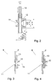
- 2 shows a possible design of the nozzle 11 and the outlet area 12 with dimensions given in millimeters by way of example.
- FIGS. 3 and 4 show sections of the powder spraying device 1, the nozzle 11 shown in FIG. 2 with the closing device 13 being shown in the open or closed position.
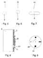
- FIG. 5 shows a top view of a typical cylindrical container 2 with an emerging powder cloud 15.
- nozzle 11 and the outlet area 12 By designing the nozzle 11 and the outlet area 12 accordingly, a different configuration of the powder cloud 15 can also be achieved, as shown in FIG. 6.
- Fig. 7 it is shown that the design of the container 2 can also be adapted to a desired shape of the cloud 15.
- FIGS. 8 and 9 A simple possibility for nozzle design is shown in FIGS. 8 and 9, an orifice 20 with different nozzle openings 21 being shown.
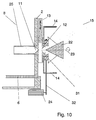
- a particularly broad and uniform powder cloud can also be achieved with the aid of an impact body (deflector) which - as is shown schematically with reference to FIGS. 10 and 11 - can also be designed as an impact body 22 rotating about an axis 23.
- An associated drive device 24, including ball bearings 31 and drive belts 32 for the rotating impact body 22 is only indicated in the drawing.
- a different design of the powder outlet area 12 is shown in FIGS. 10 and 11. In FIG. 11, a jacket 33 is placed around the impact body 22, so that a rotating gap is created, through which the shape of the powder cloud can be additionally influenced.
- the spray device 1 according to FIG. 1 can be operated in such a way that powder 8 is filled in and then the filling opening 9 is closed. The powder can then be sprayed until a minimum powder level, which is in the region of the nozzle 11, is reached.
- Figures 12 to 14 show further options for designing the powder outlet area.
- FIG. 12 shows an arrangement in which both a rotating impact body 22 and rotating high-voltage electrodes 14 are present.
- the rotatable arrangement of the components 22, 14 is indicated by the ball bearing 31 and the drive belt 32.
- FIG. 12 shows an additional air duct 30, via which additional air 28 can be fed, which can escape through air nozzles 27 in the powder outlet area 12. With the additional air 28, an additional acceleration of the powder particles and shaping of the powder cloud can be achieved.
- FIG. 13 shows an arrangement of, for example, a ring-shaped earth electrode 26 in the area between the wall of the container 2 and the impact body 22. At least a part of the ion current flows to the earth electrode 26, as a result of which the powder flow is crossed and an improved charging is achieved.
- the high-voltage electrodes 14 are attached to the rotating impact body 22. With this arrangement, at least part of the ion current flows from the high-voltage electrode to the earth electrode and the powder particles are forced to cross this ion current, whereby better charging is achieved.
Landscapes
- Electrostatic Spraying Apparatus (AREA)
- Nozzles (AREA)
- Application Of Or Painting With Fluid Materials (AREA)
- Manufacturing Of Micro-Capsules (AREA)
Applications Claiming Priority (2)
| Application Number | Priority Date | Filing Date | Title |
|---|---|---|---|
| DE19537089A DE19537089A1 (de) | 1995-10-05 | 1995-10-05 | Verfahren und Einrichtung zum Pulversprühen |
| DE19537089 | 1995-10-05 |
Publications (2)
| Publication Number | Publication Date |
|---|---|
| EP0767006A1 true EP0767006A1 (fr) | 1997-04-09 |
| EP0767006B1 EP0767006B1 (fr) | 1999-04-21 |
Family
ID=7774086
Family Applications (1)
| Application Number | Title | Priority Date | Filing Date |
|---|---|---|---|
| EP96115512A Expired - Lifetime EP0767006B1 (fr) | 1995-10-05 | 1996-09-27 | Méthode et dispositif d'alimentation en poudre d'un appareil de revêtement à poudre |
Country Status (8)
| Country | Link |
|---|---|
| US (1) | US5839669A (fr) |
| EP (1) | EP0767006B1 (fr) |
| JP (1) | JPH09248494A (fr) |
| KR (1) | KR970020204A (fr) |
| AT (1) | ATE179096T1 (fr) |
| DE (2) | DE19537089A1 (fr) |
| DK (1) | DK0767006T3 (fr) |
| ES (1) | ES2133871T3 (fr) |
Cited By (2)
| Publication number | Priority date | Publication date | Assignee | Title |
|---|---|---|---|---|
| EP1502655A3 (fr) * | 2003-07-29 | 2007-11-21 | Illinois Tool Works Inc. | Cloche de pulvérisation de poudre à électrode secondaire |
| DE102006032380A1 (de) * | 2006-07-13 | 2008-01-17 | Eisenmann Anlagenbau Gmbh & Co. Kg | Vorrichtung zum Fördern fluidisierbarer Medien |
Families Citing this family (14)
| Publication number | Priority date | Publication date | Assignee | Title |
|---|---|---|---|---|
| DE19606214B4 (de) * | 1996-02-20 | 2006-06-01 | Abb Research Ltd. | Verfahren und Einrichtung zur Steuerung des Austritts eines fluidisierten Feststoffs aus einem Behälter |
| US6220791B1 (en) * | 1999-03-11 | 2001-04-24 | Board Of Trustees Of The University Of Arkansas | Apparatus and method for the aerosolization of powders |
| DE19934920C1 (de) * | 1999-07-20 | 2000-12-21 | Schlick Gustav Gmbh & Co | Auf einen Düsenkopf aufsetzbare Düsenkappe |
| LU90639B1 (de) * | 2000-09-18 | 2002-03-19 | Wurth Paul Sa | Vorrichtung zum Einleiten von schwer fliessendem Schuettgut in eine Foerderleitung |
| DE10053295C2 (de) * | 2000-10-27 | 2002-10-31 | Eisenmann Lacktechnik Kg | Hochrotationszerstäuber zur Aufbringung von Pulverlack |
| DE10113299A1 (de) * | 2001-03-16 | 2002-09-19 | Alstom Switzerland Ltd | Verfahren zum Herstellen eines Leiterstabes |
| DE10138917A1 (de) | 2001-08-08 | 2003-03-06 | Itw Gema Ag | Pulversprühbeschichtungsvorrichtung |
| US6988698B2 (en) * | 2004-04-22 | 2006-01-24 | Lucasay Manufacturing Co. | Appliance mounting apparatus |
| US20070292218A1 (en) * | 2006-06-15 | 2007-12-20 | Robert John Suchey | Dynamic blower system, and methods of constructing and utilizing same |
| JP5014266B2 (ja) | 2008-06-11 | 2012-08-29 | モレックス インコーポレイテド | 光コネクタ |
| JP2011022198A (ja) | 2009-07-13 | 2011-02-03 | Molex Inc | 光コネクタ |
| DE102010025749B4 (de) * | 2010-06-30 | 2014-11-20 | Gema Switzerland Gmbh | Pulverversorgungsvorrichtung für eine Pulverbeschichtungsanlage |
| EP4292629A3 (fr) | 2014-09-04 | 2024-03-20 | Octet Medical, Inc. | Système de distribution de fluide électrostatique |
| CN108480079B (zh) * | 2018-04-27 | 2023-08-22 | 临朐远宏金属制品有限公司 | 一种可自动清理的供粉中心 |
Citations (6)
| Publication number | Priority date | Publication date | Assignee | Title |
|---|---|---|---|---|
| DE3529703C1 (de) * | 1985-08-20 | 1986-08-28 | Ransburg-Gema AG, St. Gallen | Spruehvorrichtung zur elektrostatischen Pulverbeschichtung |
| FR2581324A1 (fr) * | 1985-05-03 | 1986-11-07 | Porte Michel | Dispositif permettant la projection a debit regulier de produits pulverulents de granulometrie tres fine et ses differentes applications notamment pour les produits abrasifs |
| US4640310A (en) * | 1984-12-26 | 1987-02-03 | Nordson Corporation | Variable air-piloted air regulator system |
| DE3925476A1 (de) * | 1988-09-07 | 1990-03-15 | Tungsram Reszvenytarsasag | Verfahren und vorrichtung zum elektrostatischen beschichten der inneren oberflaeche von lampenkolben |
| US5018910A (en) * | 1986-11-15 | 1991-05-28 | Prazisions-Werkzeuge Ag | Process for increasing the quantity of powder dispensed in a powder coating system, as well as powder coating system |
| WO1994013405A1 (fr) * | 1992-12-17 | 1994-06-23 | Nordson Corporation | Systeme d'enduction de poudre perfectionne pour des poudres difficiles a manipuler |
Family Cites Families (25)
| Publication number | Priority date | Publication date | Assignee | Title |
|---|---|---|---|---|
| DE7341468U (de) * | 1974-02-28 | Gema Ag | Pulverzerstäuber mit Prallkörper | |
| US2621156A (en) * | 1947-04-10 | 1952-12-09 | Bowser Inc | Method for feeding filter aid |
| DE1005413B (de) * | 1955-02-28 | 1957-03-28 | Knapsack Ag | Verfahren und Vorrichtung zum Aufbringen von Schutzueberzuegen aus schmelzbaren pulverfoermigen Stoffen auf Gegenstaende beliebiger Art durch Aufspritzen des Pulvers mit einem Flammenspritzgeraet |
| US3084874A (en) * | 1959-08-12 | 1963-04-09 | Aeroprojects Inc | Method and apparatus for generating aerosols |
| US3134513A (en) * | 1960-09-30 | 1964-05-26 | Dust Control Processes Ltd | Insufflator |
| US3149884A (en) * | 1963-01-07 | 1964-09-22 | Magnet Cove Barium Corp | Pneumatic conveyer |
| US3237805A (en) * | 1964-10-28 | 1966-03-01 | Halliburton Co | Method and apparatus for dispensing particulate material |
| US3496413A (en) * | 1967-03-24 | 1970-02-17 | Electrostatic Equip Corp | Electrodes for electrostatic fluid beds |
| US3740612A (en) * | 1971-05-28 | 1973-06-19 | Champion Spark Plug Co | Apparatus for coating with electrostatically charged particulate materials |
| US3786309A (en) * | 1973-01-12 | 1974-01-15 | Gen Motors Corp | Electrostatic powder spraying method and apparatus |
| FR2314775A1 (fr) * | 1975-06-18 | 1977-01-14 | Inst Francais Du Petrole | Appareillage pour former une couche d'un produit pulverulent sur la surface d'un objet |
| SU594633A1 (ru) * | 1976-02-10 | 1986-06-30 | Предприятие П/Я В-2346 | Устройство дл нанесени порошкообразного полимерного материала в электрическом поле |
| IE45426B1 (en) * | 1976-07-15 | 1982-08-25 | Ici Ltd | Atomisation of liquids |
| DE3005678C2 (de) * | 1980-02-15 | 1982-06-24 | Basf Farben + Fasern Ag, 2000 Hamburg | Verfahren und Vorrichtung zum elektrostatischen Pulverbeschichten von Gegenständen |
| HU184030B (en) * | 1982-09-22 | 1984-06-28 | Egyesuelt Izzolampa | Apparatus for electrostatic coating bulb of light sources |
| JPS59213464A (ja) * | 1983-05-18 | 1984-12-03 | Nisshin Flour Milling Co Ltd | 粉体分散機 |
| US4615649A (en) * | 1984-10-12 | 1986-10-07 | Nordson Corporation | Powder pump having suction tube deflector |
| US4586854A (en) * | 1985-06-12 | 1986-05-06 | Nordson Corporation | Venturi powder pump having rotating diffuser |
| DE3542710A1 (de) * | 1985-12-03 | 1987-06-04 | Bohnacker Tegometall | Vorrichtung zum farbpulvereinzug beim pulverlackieren |
| DE3709543C2 (de) * | 1987-03-24 | 1996-06-05 | Wagner Gmbh J | Vorrichtung zum Zerstäuben einer Flüssigkeit |
| DE3729746A1 (de) * | 1987-09-04 | 1989-03-23 | Gema Ransburg Ag | Pulverbeschichtungsverfahren |
| DE3824908A1 (de) * | 1988-07-22 | 1990-02-01 | Gema Ransburg Ag | Verfahren und vorrichtung zum elektrostatischen spruehbeschichten |
| DE3903887C2 (de) * | 1989-02-10 | 1998-07-16 | Castolin Sa | Vorrichtung zum Flammspritzen von pulverförmigen Werkstoffen mittels autogener Flamme |
| JPH06246196A (ja) * | 1993-02-22 | 1994-09-06 | I T M Kk | 粉体供給装置、静電粉体塗装装置及び粉体流量計測装置 |
| DE4403022A1 (de) * | 1993-03-02 | 1994-09-08 | Frei Siegfried | Verfahren und Vorrichtung zum Auftragen von Pulverlack in einer Pulverlackieranlage |
-
1995
- 1995-10-05 DE DE19537089A patent/DE19537089A1/de not_active Withdrawn
-
1996
- 1996-09-27 AT AT96115512T patent/ATE179096T1/de active
- 1996-09-27 DK DK96115512T patent/DK0767006T3/da active
- 1996-09-27 ES ES96115512T patent/ES2133871T3/es not_active Expired - Lifetime
- 1996-09-27 DE DE59601699T patent/DE59601699D1/de not_active Expired - Lifetime
- 1996-09-27 EP EP96115512A patent/EP0767006B1/fr not_active Expired - Lifetime
- 1996-10-03 JP JP8263211A patent/JPH09248494A/ja not_active Withdrawn
- 1996-10-04 KR KR1019960043781A patent/KR970020204A/ko not_active Withdrawn
- 1996-10-07 US US08/726,815 patent/US5839669A/en not_active Expired - Lifetime
Patent Citations (6)
| Publication number | Priority date | Publication date | Assignee | Title |
|---|---|---|---|---|
| US4640310A (en) * | 1984-12-26 | 1987-02-03 | Nordson Corporation | Variable air-piloted air regulator system |
| FR2581324A1 (fr) * | 1985-05-03 | 1986-11-07 | Porte Michel | Dispositif permettant la projection a debit regulier de produits pulverulents de granulometrie tres fine et ses differentes applications notamment pour les produits abrasifs |
| DE3529703C1 (de) * | 1985-08-20 | 1986-08-28 | Ransburg-Gema AG, St. Gallen | Spruehvorrichtung zur elektrostatischen Pulverbeschichtung |
| US5018910A (en) * | 1986-11-15 | 1991-05-28 | Prazisions-Werkzeuge Ag | Process for increasing the quantity of powder dispensed in a powder coating system, as well as powder coating system |
| DE3925476A1 (de) * | 1988-09-07 | 1990-03-15 | Tungsram Reszvenytarsasag | Verfahren und vorrichtung zum elektrostatischen beschichten der inneren oberflaeche von lampenkolben |
| WO1994013405A1 (fr) * | 1992-12-17 | 1994-06-23 | Nordson Corporation | Systeme d'enduction de poudre perfectionne pour des poudres difficiles a manipuler |
Cited By (3)
| Publication number | Priority date | Publication date | Assignee | Title |
|---|---|---|---|---|
| EP1502655A3 (fr) * | 2003-07-29 | 2007-11-21 | Illinois Tool Works Inc. | Cloche de pulvérisation de poudre à électrode secondaire |
| DE102006032380A1 (de) * | 2006-07-13 | 2008-01-17 | Eisenmann Anlagenbau Gmbh & Co. Kg | Vorrichtung zum Fördern fluidisierbarer Medien |
| DE102006032380B4 (de) * | 2006-07-13 | 2011-06-01 | Eisenmann Anlagenbau Gmbh & Co. Kg | Vorrichtung zum Fördern fluidisierbarer Medien |
Also Published As
| Publication number | Publication date |
|---|---|
| JPH09248494A (ja) | 1997-09-22 |
| DK0767006T3 (da) | 1999-11-01 |
| EP0767006B1 (fr) | 1999-04-21 |
| KR970020204A (ko) | 1997-05-28 |
| US5839669A (en) | 1998-11-24 |
| ATE179096T1 (de) | 1999-05-15 |
| ES2133871T3 (es) | 1999-09-16 |
| DE59601699D1 (de) | 1999-05-27 |
| DE19537089A1 (de) | 1997-04-10 |
Similar Documents
| Publication | Publication Date | Title |
|---|---|---|
| EP0767006A1 (fr) | Méthode et dispositif d'alimentation en poudre d'un appareil de revêtement à poudre | |
| DE69834306T2 (de) | Vorrichtung und Verfahren zum Auftrag einer Beschichtung | |
| DE3503384C1 (de) | Spritzpistole für Beschichtungsmaterial | |
| DE69528266T2 (de) | Verfahren und vorrichtung zum kontrollierten aufbringen von partikeln auf wafers | |
| DE60222858T2 (de) | Vorrichtung und verfahren zur herstellung von stationären mehrkomponentenflüssigkeits-kapillarströmen und kapseln in mikrometergrösse und nanometergrösse | |
| DE2252474C2 (de) | Vorrichtung zum Steuern des Pulverdurchsatzes durch elektrostatische Pulverbeschichtungsanlagen oder -geräte | |
| DE69822885T2 (de) | Inhalationsvorrichtung | |
| DE2539627A1 (de) | Elektrostatische spritzpistole | |
| DE2908723A1 (de) | Verfahren und vorrichtung zum elektrostatischen spruehen einer fluessigkeit | |
| DE10203580A1 (de) | Verfahren und Vorrichtung zum Aufbringen von Teilchen auf Oberflächen | |
| DE4121455A1 (de) | Verfahren und einrichtung zum speisen von pulverbeschichtungsgeraeten mit einem pulver-luft-gemisch | |
| DE2709423C2 (de) | Verfahren und Vorrichtung zum elektrostatischen Besprühen von Gegenständen mit feinverteilten Teilchen, insbesondere zum Besprühen von Pflanzen mit Pestiziden | |
| EP1283074A2 (fr) | Dispositif de pulvérisation de poudre | |
| DE19548607A1 (de) | Pulver-Sprühbeschichtungsvorrichtung | |
| EP0123964A1 (fr) | Procédé et dispositif de pulvérisation électrostatique de particules de poudre sur une surface à revêtir | |
| EP0230964A2 (fr) | Dispositif pour appliquer de la poudre | |
| EP0792694B1 (fr) | Procédé et dispositif pour commander l'alimentation d'une poudre fluidisée à partir d'un réservoir | |
| DE102006019643B4 (de) | Vorrichtung zur pneumatischen, tribostatischen Pulverbeschichtung von Werkstücken | |
| DE3329880A1 (de) | Verfahren zum spritzbeschichten ohne luft und spritzpistole fuer das beschichten ohne luft | |
| DE3546231A1 (de) | Pulver-spruehpistole | |
| DE2555547C3 (de) | Vorrichtung zum elektrostatischen Auftragen bzw. Aufsprühen von Materialteilchen | |
| DE1097866B (de) | Vorrichtung zum elektrostatischen Farbspritzen | |
| DE2852412C2 (de) | Zerstäubungseinrichtung für Pulver zum Beschichten von Gegenständen | |
| DE1577757A1 (de) | Verfahren und Vorrichtung zur elektrostatischen Beschichtung eines Gegenstandes mit pulverisiertem UEberzugsmaterial | |
| CH666633A5 (de) | Verfahren zum elektrostatischen auftragen von pulvern und vorrichtung zur durchfuehrung des verfahrens. |
Legal Events
| Date | Code | Title | Description |
|---|---|---|---|
| PUAI | Public reference made under article 153(3) epc to a published international application that has entered the european phase |
Free format text: ORIGINAL CODE: 0009012 |
|
| AK | Designated contracting states |
Kind code of ref document: A1 Designated state(s): AT BE CH DE DK ES FR GB IT LI NL SE |
|
| 17P | Request for examination filed |
Effective date: 19970621 |
|
| 17Q | First examination report despatched |
Effective date: 19980806 |
|
| GRAG | Despatch of communication of intention to grant |
Free format text: ORIGINAL CODE: EPIDOS AGRA |
|
| GRAG | Despatch of communication of intention to grant |
Free format text: ORIGINAL CODE: EPIDOS AGRA |
|
| GRAH | Despatch of communication of intention to grant a patent |
Free format text: ORIGINAL CODE: EPIDOS IGRA |
|
| GRAH | Despatch of communication of intention to grant a patent |
Free format text: ORIGINAL CODE: EPIDOS IGRA |
|
| GRAA | (expected) grant |
Free format text: ORIGINAL CODE: 0009210 |
|
| AK | Designated contracting states |
Kind code of ref document: B1 Designated state(s): AT BE CH DE DK ES FR GB IT LI NL SE |
|
| REF | Corresponds to: |
Ref document number: 179096 Country of ref document: AT Date of ref document: 19990515 Kind code of ref document: T |
|
| REG | Reference to a national code |
Ref country code: CH Ref legal event code: EP |
|
| REF | Corresponds to: |
Ref document number: 59601699 Country of ref document: DE Date of ref document: 19990527 |
|
| ET | Fr: translation filed | ||
| GBT | Gb: translation of ep patent filed (gb section 77(6)(a)/1977) |
Effective date: 19990618 |
|
| PGFP | Annual fee paid to national office [announced via postgrant information from national office to epo] |
Ref country code: DK Payment date: 19990727 Year of fee payment: 4 |
|
| PGFP | Annual fee paid to national office [announced via postgrant information from national office to epo] |
Ref country code: SE Payment date: 19990728 Year of fee payment: 4 |
|
| PGFP | Annual fee paid to national office [announced via postgrant information from national office to epo] |
Ref country code: AT Payment date: 19990810 Year of fee payment: 4 |
|
| PGFP | Annual fee paid to national office [announced via postgrant information from national office to epo] |
Ref country code: BE Payment date: 19990913 Year of fee payment: 4 |
|
| REG | Reference to a national code |
Ref country code: ES Ref legal event code: FG2A Ref document number: 2133871 Country of ref document: ES Kind code of ref document: T3 |
|
| REG | Reference to a national code |
Ref country code: DK Ref legal event code: T3 |
|
| PLBE | No opposition filed within time limit |
Free format text: ORIGINAL CODE: 0009261 |
|
| STAA | Information on the status of an ep patent application or granted ep patent |
Free format text: STATUS: NO OPPOSITION FILED WITHIN TIME LIMIT |
|
| PGFP | Annual fee paid to national office [announced via postgrant information from national office to epo] |
Ref country code: ES Payment date: 20000228 Year of fee payment: 4 |
|
| 26N | No opposition filed | ||
| PG25 | Lapsed in a contracting state [announced via postgrant information from national office to epo] |
Ref country code: DK Free format text: LAPSE BECAUSE OF NON-PAYMENT OF DUE FEES Effective date: 20000927 Ref country code: AT Free format text: LAPSE BECAUSE OF NON-PAYMENT OF DUE FEES Effective date: 20000927 |
|
| PG25 | Lapsed in a contracting state [announced via postgrant information from national office to epo] |
Ref country code: ES Free format text: LAPSE BECAUSE OF NON-PAYMENT OF DUE FEES Effective date: 20000928 |
|
| PG25 | Lapsed in a contracting state [announced via postgrant information from national office to epo] |
Ref country code: SE Free format text: THE PATENT HAS BEEN ANNULLED BY A DECISION OF A NATIONAL AUTHORITY Effective date: 20000929 |
|
| PG25 | Lapsed in a contracting state [announced via postgrant information from national office to epo] |
Ref country code: LI Free format text: LAPSE BECAUSE OF NON-PAYMENT OF DUE FEES Effective date: 20000930 Ref country code: CH Free format text: LAPSE BECAUSE OF NON-PAYMENT OF DUE FEES Effective date: 20000930 Ref country code: BE Free format text: LAPSE BECAUSE OF NON-PAYMENT OF DUE FEES Effective date: 20000930 |
|
| BERE | Be: lapsed |
Owner name: ABB RESEARCH LTD Effective date: 20000930 |
|
| PG25 | Lapsed in a contracting state [announced via postgrant information from national office to epo] |
Ref country code: NL Free format text: LAPSE BECAUSE OF NON-PAYMENT OF DUE FEES Effective date: 20010401 |
|
| REG | Reference to a national code |
Ref country code: CH Ref legal event code: PL |
|
| EUG | Se: european patent has lapsed |
Ref document number: 96115512.4 |
|
| REG | Reference to a national code |
Ref country code: DK Ref legal event code: EBP |
|
| NLV4 | Nl: lapsed or anulled due to non-payment of the annual fee |
Effective date: 20010401 |
|
| REG | Reference to a national code |
Ref country code: GB Ref legal event code: IF02 |
|
| REG | Reference to a national code |
Ref country code: ES Ref legal event code: FD2A Effective date: 20011011 |
|
| PGFP | Annual fee paid to national office [announced via postgrant information from national office to epo] |
Ref country code: DE Payment date: 20110311 Year of fee payment: 15 Ref country code: IT Payment date: 20110324 Year of fee payment: 15 |
|
| PGFP | Annual fee paid to national office [announced via postgrant information from national office to epo] |
Ref country code: GB Payment date: 20110321 Year of fee payment: 15 |
|
| GBPC | Gb: european patent ceased through non-payment of renewal fee |
Effective date: 20110927 |
|
| PG25 | Lapsed in a contracting state [announced via postgrant information from national office to epo] |
Ref country code: IT Free format text: LAPSE BECAUSE OF NON-PAYMENT OF DUE FEES Effective date: 20110927 |
|
| REG | Reference to a national code |
Ref country code: DE Ref legal event code: R119 Ref document number: 59601699 Country of ref document: DE Effective date: 20120403 |
|
| PG25 | Lapsed in a contracting state [announced via postgrant information from national office to epo] |
Ref country code: DE Free format text: LAPSE BECAUSE OF NON-PAYMENT OF DUE FEES Effective date: 20120403 |
|
| PG25 | Lapsed in a contracting state [announced via postgrant information from national office to epo] |
Ref country code: GB Free format text: LAPSE BECAUSE OF NON-PAYMENT OF DUE FEES Effective date: 20110927 |
|
| PGFP | Annual fee paid to national office [announced via postgrant information from national office to epo] |
Ref country code: FR Payment date: 20121031 Year of fee payment: 17 |
|
| REG | Reference to a national code |
Ref country code: FR Ref legal event code: ST Effective date: 20140530 |
|
| PG25 | Lapsed in a contracting state [announced via postgrant information from national office to epo] |
Ref country code: FR Free format text: LAPSE BECAUSE OF NON-PAYMENT OF DUE FEES Effective date: 20130930 |