EP0767006A1 - Method and apparatus for feeding powder to a powder spraying device - Google Patents
Method and apparatus for feeding powder to a powder spraying device Download PDFInfo
- Publication number
- EP0767006A1 EP0767006A1 EP96115512A EP96115512A EP0767006A1 EP 0767006 A1 EP0767006 A1 EP 0767006A1 EP 96115512 A EP96115512 A EP 96115512A EP 96115512 A EP96115512 A EP 96115512A EP 0767006 A1 EP0767006 A1 EP 0767006A1
- Authority
- EP
- European Patent Office
- Prior art keywords
- powder
- chamber
- nozzle
- air
- fluidized
- Prior art date
- Legal status (The legal status is an assumption and is not a legal conclusion. Google has not performed a legal analysis and makes no representation as to the accuracy of the status listed.)
- Granted
Links
Images


Classifications
-
- B—PERFORMING OPERATIONS; TRANSPORTING
- B05—SPRAYING OR ATOMISING IN GENERAL; APPLYING FLUENT MATERIALS TO SURFACES, IN GENERAL
- B05B—SPRAYING APPARATUS; ATOMISING APPARATUS; NOZZLES
- B05B5/00—Electrostatic spraying apparatus; Spraying apparatus with means for charging the spray electrically; Apparatus for spraying liquids or other fluent materials by other electric means
- B05B5/025—Discharge apparatus, e.g. electrostatic spray guns
- B05B5/03—Discharge apparatus, e.g. electrostatic spray guns characterised by the use of gas, e.g. electrostatically assisted pneumatic spraying
- B05B5/032—Discharge apparatus, e.g. electrostatic spray guns characterised by the use of gas, e.g. electrostatically assisted pneumatic spraying for spraying particulate materials
-
- B—PERFORMING OPERATIONS; TRANSPORTING
- B05—SPRAYING OR ATOMISING IN GENERAL; APPLYING FLUENT MATERIALS TO SURFACES, IN GENERAL
- B05B—SPRAYING APPARATUS; ATOMISING APPARATUS; NOZZLES
- B05B1/00—Nozzles, spray heads or other outlets, with or without auxiliary devices such as valves, heating means
- B05B1/14—Nozzles, spray heads or other outlets, with or without auxiliary devices such as valves, heating means with multiple outlet openings; with strainers in or outside the outlet opening
- B05B1/16—Nozzles, spray heads or other outlets, with or without auxiliary devices such as valves, heating means with multiple outlet openings; with strainers in or outside the outlet opening having selectively- effective outlets
- B05B1/1627—Nozzles, spray heads or other outlets, with or without auxiliary devices such as valves, heating means with multiple outlet openings; with strainers in or outside the outlet opening having selectively- effective outlets with a selecting mechanism comprising a gate valve, a sliding valve or a cock
- B05B1/1636—Nozzles, spray heads or other outlets, with or without auxiliary devices such as valves, heating means with multiple outlet openings; with strainers in or outside the outlet opening having selectively- effective outlets with a selecting mechanism comprising a gate valve, a sliding valve or a cock by relative rotative movement of the valve elements
- B05B1/1645—Nozzles, spray heads or other outlets, with or without auxiliary devices such as valves, heating means with multiple outlet openings; with strainers in or outside the outlet opening having selectively- effective outlets with a selecting mechanism comprising a gate valve, a sliding valve or a cock by relative rotative movement of the valve elements the outlets being rotated during selection
- B05B1/1654—Nozzles, spray heads or other outlets, with or without auxiliary devices such as valves, heating means with multiple outlet openings; with strainers in or outside the outlet opening having selectively- effective outlets with a selecting mechanism comprising a gate valve, a sliding valve or a cock by relative rotative movement of the valve elements the outlets being rotated during selection about an axis parallel to the liquid passage in the stationary valve element
-
- B—PERFORMING OPERATIONS; TRANSPORTING
- B05—SPRAYING OR ATOMISING IN GENERAL; APPLYING FLUENT MATERIALS TO SURFACES, IN GENERAL
- B05B—SPRAYING APPARATUS; ATOMISING APPARATUS; NOZZLES
- B05B5/00—Electrostatic spraying apparatus; Spraying apparatus with means for charging the spray electrically; Apparatus for spraying liquids or other fluent materials by other electric means
- B05B5/025—Discharge apparatus, e.g. electrostatic spray guns
- B05B5/04—Discharge apparatus, e.g. electrostatic spray guns characterised by having rotary outlet or deflecting elements, i.e. spraying being also effected by centrifugal forces
-
- B—PERFORMING OPERATIONS; TRANSPORTING
- B05—SPRAYING OR ATOMISING IN GENERAL; APPLYING FLUENT MATERIALS TO SURFACES, IN GENERAL
- B05B—SPRAYING APPARATUS; ATOMISING APPARATUS; NOZZLES
- B05B5/00—Electrostatic spraying apparatus; Spraying apparatus with means for charging the spray electrically; Apparatus for spraying liquids or other fluent materials by other electric means
- B05B5/16—Arrangements for supplying liquids or other fluent material
- B05B5/1691—Apparatus to be carried on or by a person or with a container fixed to the discharge device
-
- B—PERFORMING OPERATIONS; TRANSPORTING
- B05—SPRAYING OR ATOMISING IN GENERAL; APPLYING FLUENT MATERIALS TO SURFACES, IN GENERAL
- B05B—SPRAYING APPARATUS; ATOMISING APPARATUS; NOZZLES
- B05B7/00—Spraying apparatus for discharge of liquids or other fluent materials from two or more sources, e.g. of liquid and air, of powder and gas
- B05B7/14—Spraying apparatus for discharge of liquids or other fluent materials from two or more sources, e.g. of liquid and air, of powder and gas designed for spraying particulate materials
- B05B7/1404—Arrangements for supplying particulate material
- B05B7/1413—Apparatus to be carried on or by a person, e.g. by hand; Apparatus comprising a container fixed to the discharge device
-
- B—PERFORMING OPERATIONS; TRANSPORTING
- B05—SPRAYING OR ATOMISING IN GENERAL; APPLYING FLUENT MATERIALS TO SURFACES, IN GENERAL
- B05B—SPRAYING APPARATUS; ATOMISING APPARATUS; NOZZLES
- B05B5/00—Electrostatic spraying apparatus; Spraying apparatus with means for charging the spray electrically; Apparatus for spraying liquids or other fluent materials by other electric means
- B05B5/16—Arrangements for supplying liquids or other fluent material
- B05B5/1683—Arrangements for supplying liquids or other fluent material specially adapted for particulate materials
Definitions
- the invention relates to a method for spraying a fluidized powder according to the preamble of claim 1. Furthermore, the invention relates to a device for performing the method.
- Such a method and an associated device are known from DE-A 12 34 802 and are used, for example, for electrostatic painting.
- the known device for powder spraying has a first chamber, into which an additional compressed air is introduced, which enters a second chamber via a frit (a pore partition).
- a powder suspended in air is fed to the second chamber via a line and further swirled with the additional compressed air emerging from the frit and guided in countercurrent.
- the powder particles emerging from the second chamber are electrically charged with the aid of electrodes which are arranged in the region of a powder / air outlet opening and are connected to a high-voltage generator and which form an electrostatic field.
- a third feed line is used in the known device, which carries air and has an improving effect on the powder / air output in the powder / air outlet area.
- the powder / air outlet is always open;
- the spraying process is controlled by controlling or regulating the flow rates of air and the air / powder mixture.
- EP-A1-05 74 305 Other devices for powder spraying, but which do not work with a two-chamber arrangement of the type described above, are from the documents DE-C1 35 29 703 and EP-A1-05 74 305 known.
- the device known from EP-A1-05 74 305 contains a rotating baffle in the air / powder outlet area to improve the powder distribution.
- the invention is based on the object of specifying a method and a device for powder spraying, by means of which a high, easily controllable ejection rate can be achieved and the powder jet can be specifically oriented.
- powder is fluidized in a closed container and a powder cloud with relatively no air content emerges.
- the powder exit rate can advantageously be determined by regulating easily measurable air pressures. No level measurements are required. There is no loss of powder during the switch-on or switch-off process.
- a powder spraying device 1 which essentially consists of a closed container 2 with a first chamber 3 and a second chamber 4.
- a compressed air supply line 5 opens into the first chamber 3.
- Compressed air 7 enters the second chamber 4 through a frit 6.
- Powder 8 is located in the second chamber 4 and can be filled through a powder supply opening 9.
- the fluidized powder 8 is removed from the area of the fluid bed through a pipe 25 and is led out through a nozzle 11 arranged laterally on the container 2 and closable with a closing device 13.
- needles are arranged as corona electrodes 14, which are connected to a high-voltage source (not shown) and which charge the emerging powder particles.
- the shape of the emerging powder cloud 15 can be determined by the nozzle 11 and additional impact bodies 16, 22 (see also FIGS. 10 to 14).
- the shape and arrangement of the electrodes 14 can be adapted to this.
- the air supply can be influenced with the aid of a controllable air inlet valve 17 and the air supply rate can be measured with the aid of a flow meter 18.
- the outlet opening 10 for fluidizing air is closed off by a controllable outlet valve 19, with which a defined flow resistance can be set.
- the air pressure p 1 in the first chamber 3 and the air pressure p 4 above the powder bed 8 can be regulated via the valves 17 and 19 with the aid of a control and regulating device, not shown.
- the pressures p 1 and p 4 are measured using suitable pressure sensors.
- the ambient air pressure is denoted by p 0 .
- p 2 With p 2 the air pressure above the frit 6 and thus immediately below the fluidized powder bed is designated.
- the pressure drop p 1 -p 2 depends on the selected frit 6 and must be taken into account when dimensioning.
- P 3 denotes the pressure inside the container 2 at the powder outlet opening 11, which can be adjusted by regulating the pressures p 1 and p 4 .
- the powder is tapped from the interior of the chamber 4 through a pipe 25 attached to the nozzle 11. This ensures a high level of uniformity of the powder output.
- the powder output rate can be set and controlled very well. High output rates in the range of 100 g / min to 1000 g / min can be achieved.
- the control behavior of the device is very good, since fluidization and spraying take place in a single device. Since there is no hose connection between the fluidization chamber 4 and the nozzle 11, there are no fluctuations in the powder output and no powder losses when switching on and off.
- the fluidization can advantageously be operated near the loosening point; then the air / powder ratio of the sprayed powder is minimal. This also ensures a high level of uniformity of the powder output.
- the shape of the powder cloud 15 is u. a. can be influenced by the shape of the nozzle 11 and the powder outlet area 12.
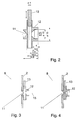
- 2 shows a possible design of the nozzle 11 and the outlet area 12 with dimensions given in millimeters by way of example.
- FIGS. 3 and 4 show sections of the powder spraying device 1, the nozzle 11 shown in FIG. 2 with the closing device 13 being shown in the open or closed position.
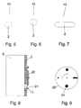
- FIG. 5 shows a top view of a typical cylindrical container 2 with an emerging powder cloud 15.
- nozzle 11 and the outlet area 12 By designing the nozzle 11 and the outlet area 12 accordingly, a different configuration of the powder cloud 15 can also be achieved, as shown in FIG. 6.
- Fig. 7 it is shown that the design of the container 2 can also be adapted to a desired shape of the cloud 15.
- FIGS. 8 and 9 A simple possibility for nozzle design is shown in FIGS. 8 and 9, an orifice 20 with different nozzle openings 21 being shown.
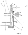
- a particularly broad and uniform powder cloud can also be achieved with the aid of an impact body (deflector) which - as is shown schematically with reference to FIGS. 10 and 11 - can also be designed as an impact body 22 rotating about an axis 23.
- An associated drive device 24, including ball bearings 31 and drive belts 32 for the rotating impact body 22 is only indicated in the drawing.
- a different design of the powder outlet area 12 is shown in FIGS. 10 and 11. In FIG. 11, a jacket 33 is placed around the impact body 22, so that a rotating gap is created, through which the shape of the powder cloud can be additionally influenced.
- the spray device 1 according to FIG. 1 can be operated in such a way that powder 8 is filled in and then the filling opening 9 is closed. The powder can then be sprayed until a minimum powder level, which is in the region of the nozzle 11, is reached.
- Figures 12 to 14 show further options for designing the powder outlet area.
- FIG. 12 shows an arrangement in which both a rotating impact body 22 and rotating high-voltage electrodes 14 are present.
- the rotatable arrangement of the components 22, 14 is indicated by the ball bearing 31 and the drive belt 32.
- FIG. 12 shows an additional air duct 30, via which additional air 28 can be fed, which can escape through air nozzles 27 in the powder outlet area 12. With the additional air 28, an additional acceleration of the powder particles and shaping of the powder cloud can be achieved.
- FIG. 13 shows an arrangement of, for example, a ring-shaped earth electrode 26 in the area between the wall of the container 2 and the impact body 22. At least a part of the ion current flows to the earth electrode 26, as a result of which the powder flow is crossed and an improved charging is achieved.
- the high-voltage electrodes 14 are attached to the rotating impact body 22. With this arrangement, at least part of the ion current flows from the high-voltage electrode to the earth electrode and the powder particles are forced to cross this ion current, whereby better charging is achieved.
Landscapes
- Electrostatic Spraying Apparatus (AREA)
- Nozzles (AREA)
- Application Of Or Painting With Fluid Materials (AREA)
- Manufacturing Of Micro-Capsules (AREA)
Abstract
Description
Die Erfindung bezieht sich auf ein Verfahren zum Sprühen eines fluidisierten Pulvers nach dem Oberbegriff des Anspruchs 1. Außerdem bezieht sich die Erfindung auf eine Einrichtung zur Durchführung des Verfahrens.The invention relates to a method for spraying a fluidized powder according to the preamble of
Ein solches Verfahren und eine zugehörige Einrichtung sind aus der DE-A 12 34 802 bekannt und werden beispielsweise zur elektrostatischen Lackierung verwendet. Die bekannte Einrichtung zum Pulversprühen weist eine erste Kammer auf, in die eine Zusatz-Druckluft eingeleitet wird, die über eine Fritte (eine Porenscheidewand) in eine zweite Kammer eintritt. Der zweiten Kammer wird ein in Luft schwebendes Pulver über eine Leitung zugeführt und mit der aus der Fritte austretenden und in Gegenstrom geführten Zusatz-Druckluft weiter verwirbelt. Eine elektrische Aufladung der aus der zweiten Kammer austretenden Pulverpartikel erfolgt mit Hilfe von Elektroden, die im Bereich einer Pulver/Luft-Austrittsöffnung angeordnet und mit einem Hochspannungsgenerator verbunden sind und die ein elektrostatisches Feld bilden.Such a method and an associated device are known from DE-A 12 34 802 and are used, for example, for electrostatic painting. The known device for powder spraying has a first chamber, into which an additional compressed air is introduced, which enters a second chamber via a frit (a pore partition). A powder suspended in air is fed to the second chamber via a line and further swirled with the additional compressed air emerging from the frit and guided in countercurrent. The powder particles emerging from the second chamber are electrically charged with the aid of electrodes which are arranged in the region of a powder / air outlet opening and are connected to a high-voltage generator and which form an electrostatic field.
Gemäß einer Ausgestaltung wird bei der bekannten Einrichtung noch mit einer dritten Zuleitung gearbeitet, die Luft führt und im Pulver/Luft-Austrittsbereich verbessernd auf die Pulver/Luftausgabe wirkt. Die Pulver/Luft-Austrittsstelle ist ständig geöffnet; eine Steuerung des Sprühvorgangs erfolgt über eine Steuerung oder Regelung der Fördermengen an Luft und der Luft/Pulvermischung.According to one embodiment, a third feed line is used in the known device, which carries air and has an improving effect on the powder / air output in the powder / air outlet area. The powder / air outlet is always open; The spraying process is controlled by controlling or regulating the flow rates of air and the air / powder mixture.
Andere Einrichtungen zum Pulversprühen, die jedoch nicht mit einer Zweikammeranordnung der vorbeschriebenen Art arbeiten, sind aus den Druckschriften DE-C1 35 29 703 und EP-A1-05 74 305 bekannt. Die aus der EP-A1-05 74 305 bekannte Einrichtung enthält im Luft/Pulver-Austrittsbereich einen rotierenden Prallkörper zur Verbesserung der Pulververteilung.Other devices for powder spraying, but which do not work with a two-chamber arrangement of the type described above, are from the documents DE-C1 35 29 703 and EP-A1-05 74 305 known. The device known from EP-A1-05 74 305 contains a rotating baffle in the air / powder outlet area to improve the powder distribution.
Allen vorgenannten Verfahren und Einrichtungen ist gemeinsam, daß mit einer relativ großen Luftmenge zum Fördern und zum Sprühen des Pulvers gearbeitet wird und die Pulverausstoßrate, die Pulverstrahlausrichtbarkeit sowie Regelbarkeit des Pulverausstoßes unbefriedigend sind.All of the above-mentioned methods and devices have in common that a relatively large amount of air is used to convey and spray the powder, and the powder discharge rate, the powder jet adjustability and controllability of the powder discharge are unsatisfactory.
Der Erfindung liegt die Aufgabe zugrunde, ein Verfahren und eine Einrichtung zum Pulversprühen anzugeben, womit eine hohe gut regelbare Ausstoßrate erzielbar ist und der Pulverstrahl gezielt ausgerichtet werden kann.The invention is based on the object of specifying a method and a device for powder spraying, by means of which a high, easily controllable ejection rate can be achieved and the powder jet can be specifically oriented.
Diese Aufgabe wird durch ein Verfahren zum Pulversprühen nach dem Oberbegriff des Anspruchs 1 durch dessen kennzeichnende Merkmale gelöst. Eine zur Durchführung des Verfahrens geeignete Einrichtung und vorteilhafte Ausgestaltungen sind in weiteren Ansprüchen angegeben und der nachstehend anhand der in den Zeichnungsfiguren dargestellten Ausführungsbeispiele zu entnehmen.This object is achieved by a method for powder spraying according to the preamble of
Beim erfindungsgemäßen Verfahren wird Pulver in einem geschlossenen Behälter fluidisiert und es tritt eine Pulverwolke mit relativ keinem Luftanteil aus. Die Pulveraustrittsrate kann vorteilhaft durch Regelung von gut meßbaren Luftdrücken bestimmt werden. Es sind keine Füllstandsmessungen erforderlich. Während des Ein- oder Ausschaltvorgangs treten keine Pulververluste auf.In the method according to the invention, powder is fluidized in a closed container and a powder cloud with relatively no air content emerges. The powder exit rate can advantageously be determined by regulating easily measurable air pressures. No level measurements are required. There is no loss of powder during the switch-on or switch-off process.
Es zeigen:
- Fig. 1
- Pulversprüheinrichtung,
- Fig. 2
- Pulveraustrittsdüse,
- Fig. 3
- Ausschnitt aus einer Sprüheinrichtung mit geöffneter Düse,
- Fig. 4
- Ausschnitt aus einer Sprüheinrichtung mit geschlossener Düse,
- Fig. 5 bis 7
- Formen von Pulverwolken,
- Fig. 8 und 9
- Sprüheinrichtung mit alternativer Düsengestaltung,
- Fig. 10 und 11
- Sprüheinrichtung mit rotierendem Prallkörper,
- Fig. 12
- Sprüheinrichtung mit rotierendem Prallkörper und rotierenden Elektroden und
- Fig. 13
- Anordnung mit ringförmiger Elektrode.
- Fig. 1
- Powder spraying device,
- Fig. 2
- Powder outlet nozzle,
- Fig. 3
- Detail from a spray device with an open nozzle,
- Fig. 4
- Detail from a spray device with a closed nozzle,
- 5 to 7
- Shapes of powder clouds,
- 8 and 9
- Spraying device with alternative nozzle design,
- 10 and 11
- Spraying device with rotating impact body,
- Fig. 12
- Spraying device with rotating impact body and rotating electrodes and
- Fig. 13
- Arrangement with an annular electrode.
Fig. 1 zeigt eine Pulversprüheinrichtung 1, die im wesentlichen aus einem geschlossenen Behälter 2 mit einer ersten Kammer 3 und einer zweiten Kammer 4 besteht. In die erste Kammer 3 mündet eine Druckluftzuleitung 5. Druckluft 7 gelangt durch eine Fritte 6 in die zweite Kammer 4. In der zweiten Kammer 4 befindet sich Pulver 8, das durch eine Pulverzufuhröffnung 9 einfüllbar ist.1 shows a
Die Luft 7, die durch die Fritte 6 in das Pulver 8 geleitet wird und dieses fluidisiert, kann durch eine Luftaustrittsöffnung 10 am Behälter 2 oberhalb des fluidisierten Pulverbetts 8 wieder austreten.The
Das fluidisierte Pulver 8 wird durch ein Rohr 25 aus dem Bereich des Fluidbetts entnommen und durch eine seitlich am Behälter 2 angeordnete und mit einer Schließeinrichtung 13 verschließbare Düse 11 herausgeführt.The fluidized
Im Pulveraustrittsbereich 12 sind Nadeln als Korona-Elektroden 14 angeordnet, die mit einer nicht dargestellten Hochspannungsquelle verbunden sind und die eine Aufladung der austretenden Pulverpartikel bewirken.In the
Die Form der austretenden Pulverwolke 15 kann durch die Düse 11 und zusätzliche Prallkörper 16, 22 (siehe auch Fig. 10 bis 14) bestimmt werden. Die Form und Anordnung der Elektroden 14 kann daran angepaßt werden.The shape of the emerging
Mit Hilfe eines steuerbaren Lufteintrittventils 17 kann die Luftzufuhr beeinflußt werden und mit Hilfe eines Durchflußmengenmessers 18 die Luftzufuhrrate gemessen werden. Die Austrittsöffnung 10 für Fluidisierungsluft ist durch ein steuerbares Austrittsventil 19 abgeschlossen, womit ein definierter Strömungswiderstand einstellbar ist.The air supply can be influenced with the aid of a controllable
Der Luftdruck p1 in der ersten Kammer 3, sowie der Luftdruck p4 oberhalb vom Pulverbett 8 können über die Ventile 17 und 19 mit Hilfe einer nicht dargestellten Steuer- und Regeleinrichtung geregelt werden. Hierbei werden die Drücke p1 und p4 mit geeigneten Drucksensoren gemessen. Mit p0 ist der Umgebungsluftdruck bezeichnet. Mit p2 ist der Luftdruck oberhalb der Fritte 6 und damit unmittelbar unterhalb des fluidisierten Pulverbetts bezeichnet. Der Druckabfall p1-p2 ist abhängig von der gewählten Fritte 6 und ist bei der Dimensionierung zu berücksichtigen.The air pressure p 1 in the
Mit p3 ist der Druck innerhalb des Behälters 2 an der Pulveraustrittsöffnung 11 bezeichnet, der durch Regelung der Drücke p1 und p4 einstellbar ist.P 3 denotes the pressure inside the
Die Menge des ausströmenden Pulvers und die Geschwindigkeit der Partikel beim Austritt wird durch den Differenzdruck ![]()
![]()
Da an den Wänden der Kammer, z.B. durch Blasen verursachte Unregelmäßigkeiten bei der Fluidisierung nicht zu vermeiden sind, wird durch ein an der Düse 11 angebrachtes Rohr 25 das Pulver aus dem Inneren der Kammer 4 abgegriffen. Damit ist eine hohe Gleichmäßigkeit des Pulverausstoßes gewährleistet.Since on the walls of the chamber, e.g. Irregularities in the fluidization caused by bubbles cannot be avoided, the powder is tapped from the interior of the
Da lediglich Drücke und eine Luftdurchflußrate zu messen und zu regeln sind (keine Füllstände), läßt sich die Pulverausstoßrate sehr gut einstellen und regeln. Es sind hohe Ausstoßraten im Bereich 100 g/min bis 1000 g/min realisierbar. Das Regelverhalten der Einrichtung ist sehr gut, da Fluidisierung und Sprühen in einer einzigen Einrichtung erfolgen. Da sich zwischen Fluidisierungskammer 4 und Düse 11 keine Schlauchverbindung befindet, treten beim Ein- und Ausschalten keine Schwankungen im Pulverausstoß und keine Pulververluste auf.Since only pressures and an air flow rate need to be measured and controlled (no fill levels), the powder output rate can be set and controlled very well. High output rates in the range of 100 g / min to 1000 g / min can be achieved. The control behavior of the device is very good, since fluidization and spraying take place in a single device. Since there is no hose connection between the
Die Fluidisierung kann vorteilhaft nahe des Lockerungspunktes betrieben werden; dann ist das Luft/Pulververhältnis des gesprühten Pulvers minimal. Außerdem ist dadurch eine hohe Gleichmäßigkeit des Pulverausstoßes gewährleistet.The fluidization can advantageously be operated near the loosening point; then the air / powder ratio of the sprayed powder is minimal. This also ensures a high level of uniformity of the powder output.
Die Form der Pulverwolke 15 ist u. a. durch die Form der Düse 11 und des Pulveraustrittsbereiches 12 beeinflußbar. In Fig. 2 ist eine mögliche Gestaltung der Düse 11 und des Austrittsbereichs 12 mit beispielhaft angegebenen Maßen in Millimetern angegeben. Die Figuren 3 und 4 zeigen Ausschnitte der Pulversprüheinrichtung 1, wobei die in Fig. 2 gezeigte Düse 11 mit Schließeinrichtung 13 in geöffneter bzw. geschlossener Stellung dargestellt ist.The shape of the
In Fig. 5 ist in Draufsicht ein typischer zylindrischer Behälter 2 mit austretender Pulverwolke 15 dargestellt. Durch entsprechende Gestaltung von Düse 11 und Austrittsbereich 12 kann aber auch eine andere Gestaltung der Pulverwolke 15 erzielt werden, wie in Fig. 6 gezeigt ist. In Fig. 7 wird gezeigt, daß auch die Gestaltung des Behälters 2 an eine angestrebte Form der Wolke 15 angepaßt werden kann.5 shows a top view of a typical
Eine einfache Möglichkeit zur Düsengestaltung ist in den Fig. 8 und 9 gezeigt, wobei eine Blende 20 mit unterschiedlichen Düsenöffnungen 21 dargestellt ist.A simple possibility for nozzle design is shown in FIGS. 8 and 9, an
Eine besonders breite und gleichmäßige Pulverwolke kann auch mit Hilfe eines Prallkörpers (Deflektors) erzielt werden, der - wie anhand der Fig. 10 und 11 schematisch gezeigt wird - auch als um eine Achse 23 rotierender Prallkörper 22 ausgeführt werden kann. Eine zugehörige Antriebseinrichtung 24, einschließlich Kugellager 31 und Antriebsriemen 32 für den rotierenden Prallkörper 22 ist in der Zeichnung lediglich angedeutet. In den Fig. 10 und 11 ist eine unterschiedliche Gestaltung des Pulveraustrittsbereichs 12 dargestellt. In Fig. 11 ist um den Prallkörper 22 noch ein Mantel 33 gelegt, so daß ein rotierender Spalt entsteht, durch den die Form der Pulverwolke noch zusätzlich beeinflußt werden kann.A particularly broad and uniform powder cloud can also be achieved with the aid of an impact body (deflector) which - as is shown schematically with reference to FIGS. 10 and 11 - can also be designed as an
Die Sprüheinrichtung 1 gemäß Fig. 1 kann so betrieben werden, daß Pulver 8 eingefüllt wird und dann die Einfüllöffnung 9 geschlossen wird. Das Pulver kann anschließend gesprüht werden, bis ein minimaler Pulverstand, der im Bereich der Düse 11 liegt, erreicht ist.The
Die Figuren 12 bis 14 zeigen weitere Möglichkeiten zur Gestaltung des Pulveraustrittsbereiches.Figures 12 to 14 show further options for designing the powder outlet area.
Fig. 12 zeigt eine Anordnung, bei der sowohl ein rotierender Prallkörper 22, als auch rotierende Hochspannungselektroden 14 vorhanden sind. Die drehbare Anordnung der Komponenten 22, 14 ist angedeutet durch das Kugellager 31 und den Antriebsriemen 32.12 shows an arrangement in which both a
Außerdem zeigt Fig. 12 einen Zusatzluft-Kanal 30, über den Zusatzluft 28 zuführbar ist, die durch Luftdüsen 27 im Pulveraustrittsbereich 12 austreten kann. Mit der Zusatzluft 28 kann eine zusätzliche Beschleunigung der Pulverteilchen und Formung der Pulverwolke erzielt werden.In addition, FIG. 12 shows an
Fig. 13 zeigt eine Anordnung einer beispielsweise ringförmigen Erdelektrode 26 im Bereich zwischen der Wand des Behälters 2 und dem Prallkörper 22. Zur Erdelektrode 26 fließt wenigstens ein Teil des Ionenstroms, wodurch der Pulverstrom gekreuzt und eine verbesserte Aufladung erreicht wird. Die Hochspannungselektroden 14 sind in diesem Fall am rotierenden Prallkörper 22 angebracht. Bei dieser Anordnung fließt zumindest ein Teil des Ionenstroms von der Hochspannungselektrode zur Erdelektrode und die Pulverteilchen sind gezwungen diesen Ionenstrom zu kreuzen, wodurch eine bessere Aufladung erreicht wird.FIG. 13 shows an arrangement of, for example, a ring-shaped
- 11
- PulversprüheinrichtungPowder spraying device
- 22nd
- geschlossener Behälterclosed container
- 33rd
- erste Kammerfirst chamber
- 44th
- zweite Kammersecond chamber
- 55
- DruckluftzuleitungCompressed air supply
- 66
- FritteFrit
- 77
- DruckluftCompressed air
- 88th
- Pulver, PulverbettPowder, powder bed
- 99
- PulverzufuhröffnungPowder feed opening
- 1010th
- LuftaustrittsöffnungAir outlet opening
- 1111
- Düsejet
- 1212th
- PulveraustrittsbereichPowder exit area
- 1313
- SchließeinrichtungLocking device
- 1414
- Korona-Elektrode (Nadelelektroden)Corona electrode (needle electrodes)
- 1515
- PulverwolkePowder cloud
- 1616
- Prallkörper (allgemein)Impact body (general)
- 1717th
- LufteintrittsventilAir inlet valve
- 1818th
- DurchflußmengenmesserFlow meter
- 1919th
- LuftaustrittsventilAir outlet valve
- 2020th
- Blendecover
- 2121
- DüsenöffnungNozzle opening
- 2222
- rotierender Prallkörperrotating impact body
- 2323
- Achseaxis
- 2424th
- AntriebseinrichtungDrive device
- 2525th
- Rohrpipe
- 2626
- ErdelektrodeEarth electrode
- 2727
- LuftdüsenAir vents
- 2828
- ZusatzluftAdditional air
- 2929
- rotierende Scheibe (mit Elektroden)rotating disc (with electrodes)
- 3030th
- Zusatzluft-KanalAdditional air duct
- 3131
- Kugellagerball-bearing
- 3232
- AntriebsriemenDrive belt
- 3333
- Mantelcoat
Claims (8)
dadurch gekennzeichnet, daß
characterized in that
dadurch gekennzeichnet, daß
characterized in that
Applications Claiming Priority (2)
| Application Number | Priority Date | Filing Date | Title |
|---|---|---|---|
| DE19537089A DE19537089A1 (en) | 1995-10-05 | 1995-10-05 | Method and device for powder spraying |
| DE19537089 | 1995-10-05 |
Publications (2)
| Publication Number | Publication Date |
|---|---|
| EP0767006A1 true EP0767006A1 (en) | 1997-04-09 |
| EP0767006B1 EP0767006B1 (en) | 1999-04-21 |
Family
ID=7774086
Family Applications (1)
| Application Number | Title | Priority Date | Filing Date |
|---|---|---|---|
| EP96115512A Expired - Lifetime EP0767006B1 (en) | 1995-10-05 | 1996-09-27 | Method and apparatus for feeding powder to a powder spraying device |
Country Status (8)
| Country | Link |
|---|---|
| US (1) | US5839669A (en) |
| EP (1) | EP0767006B1 (en) |
| JP (1) | JPH09248494A (en) |
| KR (1) | KR970020204A (en) |
| AT (1) | ATE179096T1 (en) |
| DE (2) | DE19537089A1 (en) |
| DK (1) | DK0767006T3 (en) |
| ES (1) | ES2133871T3 (en) |
Cited By (2)
| Publication number | Priority date | Publication date | Assignee | Title |
|---|---|---|---|---|
| EP1502655A3 (en) * | 2003-07-29 | 2007-11-21 | Illinois Tool Works Inc. | Powder bell with secondary charging electrode |
| DE102006032380A1 (en) * | 2006-07-13 | 2008-01-17 | Eisenmann Anlagenbau Gmbh & Co. Kg | Device for conveying fluidisable media |
Families Citing this family (14)
| Publication number | Priority date | Publication date | Assignee | Title |
|---|---|---|---|---|
| DE19606214B4 (en) * | 1996-02-20 | 2006-06-01 | Abb Research Ltd. | Method and device for controlling the discharge of a fluidized solid from a container |
| US6220791B1 (en) * | 1999-03-11 | 2001-04-24 | Board Of Trustees Of The University Of Arkansas | Apparatus and method for the aerosolization of powders |
| DE19934920C1 (en) * | 1999-07-20 | 2000-12-21 | Schlick Gustav Gmbh & Co | Interchangable jet cap for spray jet head has conical formation facing in direction of flow medium on its inside with spray openings angled parallel to conical sides |
| LU90639B1 (en) * | 2000-09-18 | 2002-03-19 | Wurth Paul Sa | Device for introducing difficult-to-flow bulk material into a conveyor line |
| DE10053295C2 (en) * | 2000-10-27 | 2002-10-31 | Eisenmann Lacktechnik Kg | High-speed rotary atomizer for applying powder coating |
| DE10113299A1 (en) * | 2001-03-16 | 2002-09-19 | Alstom Switzerland Ltd | Manufacturing conducting rods involves cutting continuous wire into sub-conductor lengths, bending sub-conductors, applying electrical insulation, assembling to make conducting rod, etc. |
| DE10138917A1 (en) | 2001-08-08 | 2003-03-06 | Itw Gema Ag | powder spraycoating |
| US6988698B2 (en) * | 2004-04-22 | 2006-01-24 | Lucasay Manufacturing Co. | Appliance mounting apparatus |
| US20070292218A1 (en) * | 2006-06-15 | 2007-12-20 | Robert John Suchey | Dynamic blower system, and methods of constructing and utilizing same |
| JP5014266B2 (en) | 2008-06-11 | 2012-08-29 | モレックス インコーポレイテド | Optical connector |
| JP2011022198A (en) | 2009-07-13 | 2011-02-03 | Molex Inc | Optical connector |
| DE102010025749B4 (en) * | 2010-06-30 | 2014-11-20 | Gema Switzerland Gmbh | Powder supply device for a powder coating system |
| EP4292629A3 (en) | 2014-09-04 | 2024-03-20 | Octet Medical, Inc. | Electrostatic fluid delivery system |
| CN108480079B (en) * | 2018-04-27 | 2023-08-22 | 临朐远宏金属制品有限公司 | A self-cleaning powder supply center |
Citations (6)
| Publication number | Priority date | Publication date | Assignee | Title |
|---|---|---|---|---|
| DE3529703C1 (en) * | 1985-08-20 | 1986-08-28 | Ransburg-Gema AG, St. Gallen | Spraying device for electrostatic powder coating |
| FR2581324A1 (en) * | 1985-05-03 | 1986-11-07 | Porte Michel | Device making it possible to spray pulverulent substances of very fine particle size at a uniform rate and its various applications especially for abrasive substances |
| US4640310A (en) * | 1984-12-26 | 1987-02-03 | Nordson Corporation | Variable air-piloted air regulator system |
| DE3925476A1 (en) * | 1988-09-07 | 1990-03-15 | Tungsram Reszvenytarsasag | Method for coating inner surface of light source covers |
| US5018910A (en) * | 1986-11-15 | 1991-05-28 | Prazisions-Werkzeuge Ag | Process for increasing the quantity of powder dispensed in a powder coating system, as well as powder coating system |
| WO1994013405A1 (en) * | 1992-12-17 | 1994-06-23 | Nordson Corporation | Improved powder coating system for difficult to handle powders |
Family Cites Families (25)
| Publication number | Priority date | Publication date | Assignee | Title |
|---|---|---|---|---|
| DE7341468U (en) * | 1974-02-28 | Gema Ag | Powder atomizer with impact body | |
| US2621156A (en) * | 1947-04-10 | 1952-12-09 | Bowser Inc | Method for feeding filter aid |
| DE1005413B (en) * | 1955-02-28 | 1957-03-28 | Knapsack Ag | Method and device for applying protective coatings made of fusible pulverulent substances to objects of any kind by spraying the powder with a flame spraying device |
| US3084874A (en) * | 1959-08-12 | 1963-04-09 | Aeroprojects Inc | Method and apparatus for generating aerosols |
| US3134513A (en) * | 1960-09-30 | 1964-05-26 | Dust Control Processes Ltd | Insufflator |
| US3149884A (en) * | 1963-01-07 | 1964-09-22 | Magnet Cove Barium Corp | Pneumatic conveyer |
| US3237805A (en) * | 1964-10-28 | 1966-03-01 | Halliburton Co | Method and apparatus for dispensing particulate material |
| US3496413A (en) * | 1967-03-24 | 1970-02-17 | Electrostatic Equip Corp | Electrodes for electrostatic fluid beds |
| US3740612A (en) * | 1971-05-28 | 1973-06-19 | Champion Spark Plug Co | Apparatus for coating with electrostatically charged particulate materials |
| US3786309A (en) * | 1973-01-12 | 1974-01-15 | Gen Motors Corp | Electrostatic powder spraying method and apparatus |
| FR2314775A1 (en) * | 1975-06-18 | 1977-01-14 | Inst Francais Du Petrole | APPARATUS FOR FORMING A LAYER OF A PULVERULENT PRODUCT ON THE SURFACE OF AN OBJECT |
| SU594633A1 (en) * | 1976-02-10 | 1986-06-30 | Предприятие П/Я В-2346 | Device for applying powder-like polymeric material in electric field |
| IE45426B1 (en) * | 1976-07-15 | 1982-08-25 | Ici Ltd | Atomisation of liquids |
| DE3005678C2 (en) * | 1980-02-15 | 1982-06-24 | Basf Farben + Fasern Ag, 2000 Hamburg | Method and device for electrostatic powder coating of objects |
| HU184030B (en) * | 1982-09-22 | 1984-06-28 | Egyesuelt Izzolampa | Apparatus for electrostatic coating bulb of light sources |
| JPS59213464A (en) * | 1983-05-18 | 1984-12-03 | Nisshin Flour Milling Co Ltd | Powder dispersing machine |
| US4615649A (en) * | 1984-10-12 | 1986-10-07 | Nordson Corporation | Powder pump having suction tube deflector |
| US4586854A (en) * | 1985-06-12 | 1986-05-06 | Nordson Corporation | Venturi powder pump having rotating diffuser |
| DE3542710A1 (en) * | 1985-12-03 | 1987-06-04 | Bohnacker Tegometall | Apparatus for the feed of paint powder in powder coating |
| DE3709543C2 (en) * | 1987-03-24 | 1996-06-05 | Wagner Gmbh J | Device for atomizing a liquid |
| DE3729746A1 (en) * | 1987-09-04 | 1989-03-23 | Gema Ransburg Ag | Powder coating method |
| DE3824908A1 (en) * | 1988-07-22 | 1990-02-01 | Gema Ransburg Ag | METHOD AND DEVICE FOR ELECTROSTATIC SPRAY COATING |
| DE3903887C2 (en) * | 1989-02-10 | 1998-07-16 | Castolin Sa | Device for flame spraying powdery materials by means of an autogenous flame |
| JPH06246196A (en) * | 1993-02-22 | 1994-09-06 | I T M Kk | Powder supplying device, electrostatic powder coating device and powder flow rate measuring instrument |
| DE4403022A1 (en) * | 1993-03-02 | 1994-09-08 | Frei Siegfried | Method and device for applying powder coating in a powder coating installation |
-
1995
- 1995-10-05 DE DE19537089A patent/DE19537089A1/en not_active Withdrawn
-
1996
- 1996-09-27 AT AT96115512T patent/ATE179096T1/en active
- 1996-09-27 DK DK96115512T patent/DK0767006T3/en active
- 1996-09-27 ES ES96115512T patent/ES2133871T3/en not_active Expired - Lifetime
- 1996-09-27 DE DE59601699T patent/DE59601699D1/en not_active Expired - Lifetime
- 1996-09-27 EP EP96115512A patent/EP0767006B1/en not_active Expired - Lifetime
- 1996-10-03 JP JP8263211A patent/JPH09248494A/en not_active Withdrawn
- 1996-10-04 KR KR1019960043781A patent/KR970020204A/en not_active Withdrawn
- 1996-10-07 US US08/726,815 patent/US5839669A/en not_active Expired - Lifetime
Patent Citations (6)
| Publication number | Priority date | Publication date | Assignee | Title |
|---|---|---|---|---|
| US4640310A (en) * | 1984-12-26 | 1987-02-03 | Nordson Corporation | Variable air-piloted air regulator system |
| FR2581324A1 (en) * | 1985-05-03 | 1986-11-07 | Porte Michel | Device making it possible to spray pulverulent substances of very fine particle size at a uniform rate and its various applications especially for abrasive substances |
| DE3529703C1 (en) * | 1985-08-20 | 1986-08-28 | Ransburg-Gema AG, St. Gallen | Spraying device for electrostatic powder coating |
| US5018910A (en) * | 1986-11-15 | 1991-05-28 | Prazisions-Werkzeuge Ag | Process for increasing the quantity of powder dispensed in a powder coating system, as well as powder coating system |
| DE3925476A1 (en) * | 1988-09-07 | 1990-03-15 | Tungsram Reszvenytarsasag | Method for coating inner surface of light source covers |
| WO1994013405A1 (en) * | 1992-12-17 | 1994-06-23 | Nordson Corporation | Improved powder coating system for difficult to handle powders |
Cited By (3)
| Publication number | Priority date | Publication date | Assignee | Title |
|---|---|---|---|---|
| EP1502655A3 (en) * | 2003-07-29 | 2007-11-21 | Illinois Tool Works Inc. | Powder bell with secondary charging electrode |
| DE102006032380A1 (en) * | 2006-07-13 | 2008-01-17 | Eisenmann Anlagenbau Gmbh & Co. Kg | Device for conveying fluidisable media |
| DE102006032380B4 (en) * | 2006-07-13 | 2011-06-01 | Eisenmann Anlagenbau Gmbh & Co. Kg | Device for conveying fluidisable media |
Also Published As
| Publication number | Publication date |
|---|---|
| JPH09248494A (en) | 1997-09-22 |
| DK0767006T3 (en) | 1999-11-01 |
| EP0767006B1 (en) | 1999-04-21 |
| KR970020204A (en) | 1997-05-28 |
| US5839669A (en) | 1998-11-24 |
| ATE179096T1 (en) | 1999-05-15 |
| ES2133871T3 (en) | 1999-09-16 |
| DE59601699D1 (en) | 1999-05-27 |
| DE19537089A1 (en) | 1997-04-10 |
Similar Documents
| Publication | Publication Date | Title |
|---|---|---|
| EP0767006A1 (en) | Method and apparatus for feeding powder to a powder spraying device | |
| DE69834306T2 (en) | Apparatus and method for applying a coating | |
| DE3503384C1 (en) | Spray gun for coating material | |
| DE69528266T2 (en) | METHOD AND DEVICE FOR THE CONTROLLED APPLICATION OF PARTICLES TO WAFERS | |
| DE60222858T2 (en) | APPARATUS AND METHOD FOR PRODUCING STATIONARY MULTICOMPONENT LIQUID CAPILLARY FLOWS AND CAPSULES IN MICROMETER SIZE AND NANOMETER SIZE | |
| DE2252474C2 (en) | Device for controlling the powder throughput through electrostatic powder coating systems or devices | |
| DE69822885T2 (en) | INHALATION DEVICE | |
| DE2539627A1 (en) | ELECTROSTATIC SPRAY GUN | |
| DE2908723A1 (en) | METHOD AND DEVICE FOR ELECTROSTATIC SPRAYING A LIQUID | |
| DE10203580A1 (en) | Method and device for applying particles to surfaces | |
| DE4121455A1 (en) | METHOD AND DEVICE FOR FEEDING POWDER COATING DEVICES WITH A POWDER-AIR MIXTURE | |
| DE2709423C2 (en) | Method and device for the electrostatic spraying of objects with finely divided particles, in particular for spraying plants with pesticides | |
| EP1283074A2 (en) | Powder coating apparatus | |
| DE19548607A1 (en) | Powder spray coater | |
| EP0123964A1 (en) | Process and device for the electrostatic spraying of powder particles onto a surface | |
| EP0230964A2 (en) | Powder application device | |
| EP0792694B1 (en) | Process and device for controlling the flow of a fluidised powder from a container | |
| DE102006019643B4 (en) | Device for pneumatic, tribostatic powder coating of workpieces | |
| DE3329880A1 (en) | METHOD FOR SPRAY COATING WITHOUT AIR AND SPRAY GUN FOR COATING WITHOUT AIR | |
| DE3546231A1 (en) | Powder spray gun | |
| DE2555547C3 (en) | Device for the electrostatic application or spraying of material particles | |
| DE1097866B (en) | Device for electrostatic paint spraying | |
| DE2852412C2 (en) | Atomizing device for powder for coating objects | |
| DE1577757A1 (en) | Method and device for the electrostatic coating of an object with pulverized coating material | |
| CH666633A5 (en) | METHOD FOR ELECTROSTATICALLY APPLYING POWDERS AND DEVICE FOR IMPLEMENTING THE METHOD. |
Legal Events
| Date | Code | Title | Description |
|---|---|---|---|
| PUAI | Public reference made under article 153(3) epc to a published international application that has entered the european phase |
Free format text: ORIGINAL CODE: 0009012 |
|
| AK | Designated contracting states |
Kind code of ref document: A1 Designated state(s): AT BE CH DE DK ES FR GB IT LI NL SE |
|
| 17P | Request for examination filed |
Effective date: 19970621 |
|
| 17Q | First examination report despatched |
Effective date: 19980806 |
|
| GRAG | Despatch of communication of intention to grant |
Free format text: ORIGINAL CODE: EPIDOS AGRA |
|
| GRAG | Despatch of communication of intention to grant |
Free format text: ORIGINAL CODE: EPIDOS AGRA |
|
| GRAH | Despatch of communication of intention to grant a patent |
Free format text: ORIGINAL CODE: EPIDOS IGRA |
|
| GRAH | Despatch of communication of intention to grant a patent |
Free format text: ORIGINAL CODE: EPIDOS IGRA |
|
| GRAA | (expected) grant |
Free format text: ORIGINAL CODE: 0009210 |
|
| AK | Designated contracting states |
Kind code of ref document: B1 Designated state(s): AT BE CH DE DK ES FR GB IT LI NL SE |
|
| REF | Corresponds to: |
Ref document number: 179096 Country of ref document: AT Date of ref document: 19990515 Kind code of ref document: T |
|
| REG | Reference to a national code |
Ref country code: CH Ref legal event code: EP |
|
| REF | Corresponds to: |
Ref document number: 59601699 Country of ref document: DE Date of ref document: 19990527 |
|
| ET | Fr: translation filed | ||
| GBT | Gb: translation of ep patent filed (gb section 77(6)(a)/1977) |
Effective date: 19990618 |
|
| PGFP | Annual fee paid to national office [announced via postgrant information from national office to epo] |
Ref country code: DK Payment date: 19990727 Year of fee payment: 4 |
|
| PGFP | Annual fee paid to national office [announced via postgrant information from national office to epo] |
Ref country code: SE Payment date: 19990728 Year of fee payment: 4 |
|
| PGFP | Annual fee paid to national office [announced via postgrant information from national office to epo] |
Ref country code: AT Payment date: 19990810 Year of fee payment: 4 |
|
| PGFP | Annual fee paid to national office [announced via postgrant information from national office to epo] |
Ref country code: BE Payment date: 19990913 Year of fee payment: 4 |
|
| REG | Reference to a national code |
Ref country code: ES Ref legal event code: FG2A Ref document number: 2133871 Country of ref document: ES Kind code of ref document: T3 |
|
| REG | Reference to a national code |
Ref country code: DK Ref legal event code: T3 |
|
| PLBE | No opposition filed within time limit |
Free format text: ORIGINAL CODE: 0009261 |
|
| STAA | Information on the status of an ep patent application or granted ep patent |
Free format text: STATUS: NO OPPOSITION FILED WITHIN TIME LIMIT |
|
| PGFP | Annual fee paid to national office [announced via postgrant information from national office to epo] |
Ref country code: ES Payment date: 20000228 Year of fee payment: 4 |
|
| 26N | No opposition filed | ||
| PG25 | Lapsed in a contracting state [announced via postgrant information from national office to epo] |
Ref country code: DK Free format text: LAPSE BECAUSE OF NON-PAYMENT OF DUE FEES Effective date: 20000927 Ref country code: AT Free format text: LAPSE BECAUSE OF NON-PAYMENT OF DUE FEES Effective date: 20000927 |
|
| PG25 | Lapsed in a contracting state [announced via postgrant information from national office to epo] |
Ref country code: ES Free format text: LAPSE BECAUSE OF NON-PAYMENT OF DUE FEES Effective date: 20000928 |
|
| PG25 | Lapsed in a contracting state [announced via postgrant information from national office to epo] |
Ref country code: SE Free format text: THE PATENT HAS BEEN ANNULLED BY A DECISION OF A NATIONAL AUTHORITY Effective date: 20000929 |
|
| PG25 | Lapsed in a contracting state [announced via postgrant information from national office to epo] |
Ref country code: LI Free format text: LAPSE BECAUSE OF NON-PAYMENT OF DUE FEES Effective date: 20000930 Ref country code: CH Free format text: LAPSE BECAUSE OF NON-PAYMENT OF DUE FEES Effective date: 20000930 Ref country code: BE Free format text: LAPSE BECAUSE OF NON-PAYMENT OF DUE FEES Effective date: 20000930 |
|
| BERE | Be: lapsed |
Owner name: ABB RESEARCH LTD Effective date: 20000930 |
|
| PG25 | Lapsed in a contracting state [announced via postgrant information from national office to epo] |
Ref country code: NL Free format text: LAPSE BECAUSE OF NON-PAYMENT OF DUE FEES Effective date: 20010401 |
|
| REG | Reference to a national code |
Ref country code: CH Ref legal event code: PL |
|
| EUG | Se: european patent has lapsed |
Ref document number: 96115512.4 |
|
| REG | Reference to a national code |
Ref country code: DK Ref legal event code: EBP |
|
| NLV4 | Nl: lapsed or anulled due to non-payment of the annual fee |
Effective date: 20010401 |
|
| REG | Reference to a national code |
Ref country code: GB Ref legal event code: IF02 |
|
| REG | Reference to a national code |
Ref country code: ES Ref legal event code: FD2A Effective date: 20011011 |
|
| PGFP | Annual fee paid to national office [announced via postgrant information from national office to epo] |
Ref country code: DE Payment date: 20110311 Year of fee payment: 15 Ref country code: IT Payment date: 20110324 Year of fee payment: 15 |
|
| PGFP | Annual fee paid to national office [announced via postgrant information from national office to epo] |
Ref country code: GB Payment date: 20110321 Year of fee payment: 15 |
|
| GBPC | Gb: european patent ceased through non-payment of renewal fee |
Effective date: 20110927 |
|
| PG25 | Lapsed in a contracting state [announced via postgrant information from national office to epo] |
Ref country code: IT Free format text: LAPSE BECAUSE OF NON-PAYMENT OF DUE FEES Effective date: 20110927 |
|
| REG | Reference to a national code |
Ref country code: DE Ref legal event code: R119 Ref document number: 59601699 Country of ref document: DE Effective date: 20120403 |
|
| PG25 | Lapsed in a contracting state [announced via postgrant information from national office to epo] |
Ref country code: DE Free format text: LAPSE BECAUSE OF NON-PAYMENT OF DUE FEES Effective date: 20120403 |
|
| PG25 | Lapsed in a contracting state [announced via postgrant information from national office to epo] |
Ref country code: GB Free format text: LAPSE BECAUSE OF NON-PAYMENT OF DUE FEES Effective date: 20110927 |
|
| PGFP | Annual fee paid to national office [announced via postgrant information from national office to epo] |
Ref country code: FR Payment date: 20121031 Year of fee payment: 17 |
|
| REG | Reference to a national code |
Ref country code: FR Ref legal event code: ST Effective date: 20140530 |
|
| PG25 | Lapsed in a contracting state [announced via postgrant information from national office to epo] |
Ref country code: FR Free format text: LAPSE BECAUSE OF NON-PAYMENT OF DUE FEES Effective date: 20130930 |