EP0780160A1 - Powder spray coating device - Google Patents
Powder spray coating device Download PDFInfo
- Publication number
- EP0780160A1 EP0780160A1 EP96115438A EP96115438A EP0780160A1 EP 0780160 A1 EP0780160 A1 EP 0780160A1 EP 96115438 A EP96115438 A EP 96115438A EP 96115438 A EP96115438 A EP 96115438A EP 0780160 A1 EP0780160 A1 EP 0780160A1
- Authority
- EP
- European Patent Office
- Prior art keywords
- air
- conveying
- additional
- conveying air
- air outlet
- Prior art date
- Legal status (The legal status is an assumption and is not a legal conclusion. Google has not performed a legal analysis and makes no representation as to the accuracy of the status listed.)
- Granted
Links
- 238000005507 spraying Methods 0.000 title claims description 28
- 229940098458 powder spray Drugs 0.000 title claims description 22
- 239000000843 powder Substances 0.000 claims abstract description 49
- 239000007921 spray Substances 0.000 claims description 21
- 239000011248 coating agent Substances 0.000 claims description 16
- 238000000576 coating method Methods 0.000 claims description 16
- 230000000007 visual effect Effects 0.000 claims description 2
- 238000011144 upstream manufacturing Methods 0.000 claims 6
- 239000007789 gas Substances 0.000 description 6
- 239000002245 particle Substances 0.000 description 5
- 230000006870 function Effects 0.000 description 4
- 230000015654 memory Effects 0.000 description 4
- 238000004590 computer program Methods 0.000 description 3
- 238000005259 measurement Methods 0.000 description 3
- 230000005611 electricity Effects 0.000 description 2
- 238000009530 blood pressure measurement Methods 0.000 description 1
- 238000001514 detection method Methods 0.000 description 1
- 230000000694 effects Effects 0.000 description 1
- 239000000203 mixture Substances 0.000 description 1
- 238000010926 purge Methods 0.000 description 1
- 230000001105 regulatory effect Effects 0.000 description 1
- 230000002123 temporal effect Effects 0.000 description 1
Images


Classifications
-
- B—PERFORMING OPERATIONS; TRANSPORTING
- B05—SPRAYING OR ATOMISING IN GENERAL; APPLYING FLUENT MATERIALS TO SURFACES, IN GENERAL
- B05B—SPRAYING APPARATUS; ATOMISING APPARATUS; NOZZLES
- B05B12/00—Arrangements for controlling delivery; Arrangements for controlling the spray area
- B05B12/08—Arrangements for controlling delivery; Arrangements for controlling the spray area responsive to condition of liquid or other fluent material to be discharged, of ambient medium or of target ; responsive to condition of spray devices or of supply means, e.g. pipes, pumps or their drive means
- B05B12/12—Arrangements for controlling delivery; Arrangements for controlling the spray area responsive to condition of liquid or other fluent material to be discharged, of ambient medium or of target ; responsive to condition of spray devices or of supply means, e.g. pipes, pumps or their drive means responsive to conditions of ambient medium or target, e.g. humidity, temperature position or movement of the target relative to the spray apparatus
- B05B12/122—Arrangements for controlling delivery; Arrangements for controlling the spray area responsive to condition of liquid or other fluent material to be discharged, of ambient medium or of target ; responsive to condition of spray devices or of supply means, e.g. pipes, pumps or their drive means responsive to conditions of ambient medium or target, e.g. humidity, temperature position or movement of the target relative to the spray apparatus responsive to presence or shape of target
-
- B—PERFORMING OPERATIONS; TRANSPORTING
- B05—SPRAYING OR ATOMISING IN GENERAL; APPLYING FLUENT MATERIALS TO SURFACES, IN GENERAL
- B05B—SPRAYING APPARATUS; ATOMISING APPARATUS; NOZZLES
- B05B12/00—Arrangements for controlling delivery; Arrangements for controlling the spray area
- B05B12/004—Arrangements for controlling delivery; Arrangements for controlling the spray area comprising sensors for monitoring the delivery, e.g. by displaying the sensed value or generating an alarm
- B05B12/006—Pressure or flow rate sensors
-
- B—PERFORMING OPERATIONS; TRANSPORTING
- B05—SPRAYING OR ATOMISING IN GENERAL; APPLYING FLUENT MATERIALS TO SURFACES, IN GENERAL
- B05B—SPRAYING APPARATUS; ATOMISING APPARATUS; NOZZLES
- B05B12/00—Arrangements for controlling delivery; Arrangements for controlling the spray area
- B05B12/08—Arrangements for controlling delivery; Arrangements for controlling the spray area responsive to condition of liquid or other fluent material to be discharged, of ambient medium or of target ; responsive to condition of spray devices or of supply means, e.g. pipes, pumps or their drive means
- B05B12/085—Arrangements for controlling delivery; Arrangements for controlling the spray area responsive to condition of liquid or other fluent material to be discharged, of ambient medium or of target ; responsive to condition of spray devices or of supply means, e.g. pipes, pumps or their drive means responsive to flow or pressure of liquid or other fluent material to be discharged
-
- B—PERFORMING OPERATIONS; TRANSPORTING
- B05—SPRAYING OR ATOMISING IN GENERAL; APPLYING FLUENT MATERIALS TO SURFACES, IN GENERAL
- B05B—SPRAYING APPARATUS; ATOMISING APPARATUS; NOZZLES
- B05B7/00—Spraying apparatus for discharge of liquids or other fluent materials from two or more sources, e.g. of liquid and air, of powder and gas
- B05B7/14—Spraying apparatus for discharge of liquids or other fluent materials from two or more sources, e.g. of liquid and air, of powder and gas designed for spraying particulate materials
- B05B7/1404—Arrangements for supplying particulate material
-
- B—PERFORMING OPERATIONS; TRANSPORTING
- B05—SPRAYING OR ATOMISING IN GENERAL; APPLYING FLUENT MATERIALS TO SURFACES, IN GENERAL
- B05B—SPRAYING APPARATUS; ATOMISING APPARATUS; NOZZLES
- B05B5/00—Electrostatic spraying apparatus; Spraying apparatus with means for charging the spray electrically; Apparatus for spraying liquids or other fluent materials by other electric means
- B05B5/16—Arrangements for supplying liquids or other fluent material
- B05B5/1683—Arrangements for supplying liquids or other fluent material specially adapted for particulate materials
Definitions
- the invention relates to a powder spray coating device according to the preamble of claim 1.
- An electrostatic powder spray coating device of this type is known from EP-B 0 412 489.
- the known device contains an injector for the pneumatic conveying of coating powder from a powder container to a spraying device; a conveying air line connected to the injector, which is provided with an adjustable first pressure setting device; an additional gas line connected to the injector, which is provided with an adjustable second pressure setting device; and a gas supply line for supplying compressed air to the two pressure setting devices.
- a first flow meter is arranged in the gas supply line and displays the total amount of air consisting of conveying air and additional air.
- a second additional gas line or purging air line is connected to the spraying device, for example to prevent powder particles from an electrode for electrostatically charging the powder, so that the powder particles cannot adhere to the electrode.
- the pressure setting devices can be adjustable pressure regulators, adjustable flow restrictors, adjustable taps or the like. Air is the preferred medium, but other gases can also be used.
- the amount of powder delivered by the injector depends on the amount of feed air supplied to the injector.
- the powder flow rate also depends on the amount of additional air if the additional air is introduced into the negative pressure area of the injector. However, the additional air is common fed downstream of the negative pressure area to the conveying air powder stream. The additional air can therefore perform two different tasks, namely influencing the powder flow rate on the one hand and influencing the flow rate of the powder flow downstream of the injector on the other.
- the spray devices are preferably designed such that they are "electrostatic" can be coated.
- This means that the powder is electrostatically charged so that it adheres better to the object to be coated before the powder layer is subsequently melted onto the object in an oven, and thus fewer powder particles miss the object due to the scattering effect.
- the electrostatic charge can be generated by friction of the powder particles on a channel wall in the spray device, so-called frictional electricity or triboelectricity, or by high-voltage electricity on a high-voltage electrode, which is arranged in or next to the flow path of the coating powder and preferably arranged in or on the spray device is.
- the high voltage generator for generating the high voltage for the electrode can be arranged externally or within the spray device.
- High voltage electrostatic spray coaters are known, for example, from US Pat. No. 4,196,465.
- the coating of objects usually takes place in cabins through which the objects are transported and into which the spray devices, so-called spray guns, are inserted through wall openings.
- the aim of the invention is to achieve the object of designing the powder spray coating device in such a way that the time required for a color change and an object change is reduced.
- an operator can manually set what he believes to be the optimum values for conveying air and additional air for coating a specific object. Furthermore, if the automatic mode is not working satisfactorily, it can be switched over to manual mode at any time.
- the optimal values for conveying air and additional air determined by the operator or already by the manufacturer of the powder spray coating device can be stored for several different objects in the control device provided for automatic operation.
- the pressures and flow rates of the conveying air and the additional air are automatically set by the control device to the optimal values for the object in question, which values are stored in the control device.
- the relevant object type and / or the required object conveying speed can be selected on the control device, which then automatically has the correct pressures and flow rates for the conveying air and the additional air.
- each spray device is assigned its own control unit, and the conveying air and the additional air have to be set individually on each control unit for the associated spray device, then it is easy to see the temporal advantage of the invention, by means of which the relevant object, the relevant powder and / or the relevant object conveying speed need only be selected on the higher-level control device. Different types of objects are often coated in succession in a cabin.
- the invention makes it possible to arrange an object sensor in the transport path of the objects, which is connected to the control device and reports to it the presence and / or the type of the object.
- the control device can automatically give corresponding signals to the control device for the automatic setting of the conveying air and the additional air.
- the control device is preferably computerized and contains memories for storing the conveying air values, additional air values and conveying speed values required for different objects and / or different types of powder and / or different object conveying speeds. These values can be pressures and / or flow rates and / or electrical voltages.
- one control device can control several control devices.
- the powder spray coating device according to the invention shown in FIG. 1 contains the following parts: a control unit 2; a electronic control device 4; an injector 6 acting as a pneumatic pump, a powder spray device 8; a cabin 10.
- a conveying air line 12 connects a conveying air outlet 14 of the control device 2 to a conveying air inlet 15 of the injector 6.
- the conveying air 15 generates a negative pressure in the injector 6, which sucks coating powder from a powder container 18 into the conveying air flow via a suction line 16 and together with it via a powder line 20 is fed to the spraying device 8, which sprays the powder 22 in the booth 10 onto an object 24 to be coated.
- the object 24 is transported by a conveyor device 25, on which it hangs, through wall openings 26 of the cabin 10.
- the injector 6 can be supplied with additional air from an additional air line 30 in its vacuum region 28 or downstream thereof, which has an additional air outlet 32 of the Control unit 2 connects in terms of flow with an additional air inlet 33 of the injector 6.
- the powder can in the spray device 8 either by friction on a channel wall or, according to FIG. 1, by the high voltage of a High voltage electrode 34 are electrostatically charged, which is arranged in the spray device 8 in the flow path of the powder and receives high voltage from a high voltage generator 36 integrated in the spray device 8.
- the high-voltage generator 36 receives its low-voltage supply voltage via an electrical line 38, which is connected to an adjustable potentiometer 40 of the control unit 2, so that the high voltage 34 can be switched on and off and adjusted by adjusting the potentiometer 40.
- electrode air flows around them from an electrode air line 42, which fluidly connects an electrode air outlet 44 of the control device 2 to an electrode air inlet 45 of the spraying device 8.
- the control device 2 contains, in addition to the potentiometer 40 and the compressed air outlets 14, 32, 44: a compressed air supply connection 48 which is connected via a pressure setting element 49, for example an adjustable pressure regulator or an adjustable pressure reducing valve, and a solenoid valve 60 with a compressed air outlet of this solenoid valve 60 can be connected, this compressed air outlet forming the internal compressed air inlet 62 of the control unit 2 and always is only fluidly connected to the compressed air supply line connection 48 when the solenoid valve 60 is switched on by a main switch 64 of the control unit 2, the main switch 64 also simultaneously switching on the power supply to the potentiometer 40 or, when the solenoid valve 60 is switched off, also the power supply at the same time Potentiometer 40 switches off; a switch 66; a manually adjustable first conveying air adjusting element 68 in the form of an adjustable pressure regulator or an adjustable flow restrictor; a conveying air meter 70 (e.g., pressure meter and / or flow meter) fluidly connected to or downstream
- the switch 66 can be switched manually or remotely by the electronic (or pneumatic or hydraulic) control device 4 between a manual mode position and an automatic mode position.
- the change-over switch 66 connects its compressed air inlet "P" in the manual operating position to a compressed air outlet "H", and in its automatic operating position to a compressed air outlet "A".
- An electrode air flow path 92 leads from the internal compressed air inlet 62 via the electrode air flow meter 90 and then via the electrode air adjusting element 88 to the electrode air outlet 44, independently of the switch 66.
- the electrode air could also be via the switch 66 be guided and then be switched on and off by the switch 66.
- a first delivery air path 94 leads from a manual operation compressed air line 95, which is connected to the manual operation compressed air outlet "H" of the switch 66, via the manual delivery air setting element 68 and a first OR valve 96 to the delivery air outlet 14.
- a second delivery air route 98 for automatic operation leads from the automatic compressed air outlet "A" of the switch 66 via an automatic operation compressed air line 99 to Automatic conveying air adjusting element 78 and then via the first OR valve 96 to the conveying air outlet 14.
- the first OR valve 96 is automatically switched by the conveying air pressure, so that it connects only the conveying air path with the conveying air outlet 14 from the two conveying air paths 94 and 98, in which conveying air is supplied, while the OR valve 96 simultaneously closes the inlet of the other conveying air path 98 or 94 in question.
- a first additional air path 100 for manual operation leads from the manual operation compressed air line 95, which is connected to the manual operation compressed air outlet "H" of the switch 66, via the first additional air adjustment element 72 for manual operation to a first compressed air inlet of a second OR valve 102 and from its compressed air outlet to the additional air outlet 32.
- a second additional air path 104 leads from the automatic mode compressed air line 99, which is connected to the automatic mode compressed air outlet "A" of the switch 66, via the second additional air setting element 82 for automatic mode to a second compressed air inlet of the second OR valve 102 and from its compressed air outlet also to the additional air outlet 32.
- the second OR valve 102 connects only that of the two additional air paths 100 or 104 to the additional air outlet 32, in which additional air is conveyed, while this second OR valve 102 has its compressed air inlet for the respective other inlet set airway 104 or 102 closes.
- FIG. 2 the lines through which compressed air flows in manual operation are marked by additional dash-dotted lines.
- the switch 66 is in manual mode, so that compressed air from the internal compressed air inlet 62 can only reach the manual mode compressed air outlet "H" of the switch 66 via the compressed air supply line 86, but not to its automatic mode compressed air outlet "A".
- the conveying air flows only via the first manual conveying air adjusting element 68 to the conveying air outlet 14, but not via the second automatic conveying air adjusting element 78.
- the additional air flows only via the first manual operating auxiliary air adjusting element 72 to the auxiliary air outlet 32, but not via the second automatic operating auxiliary air adjusting element 82
- the changeover switch 66 can be set manually or by the higher-level control device 4 from automatic operation to manual operation or vice versa, it being possible to switch the changeover switch 66 manually into another position, in particular into the automatic operation position, even if the higher-level control device 4 is manual operation demands.
- the basic position of the switch 66 is manual. This is advantageous in the event of a fault in the control device 4.
- the switch 66 is switched to automatic mode, so that compressed air from the internal compressed air inlet 62 via the compressed air supply line 86 from the changeover compressed air inlet "P" can only get to the automatic operation compressed air outlet "A" of the changeover switch 66, but not to its manual operation compressed air outlet "H".
- the lines through which compressed air flows in automatic mode are marked by a dashed line added to them.
- conveying air can only reach the conveying air outlet 14 via the automatic mode conveying air setting element 78 of the second conveying air path 98, but not via the manual mode conveying air setting element 68 of the first conveying air path 94.
- the automatic operating conveying air adjusting element 78 is connected to the control device 4 via an electrical (pneumatic or hydraulic) line 106 and is controlled by it in order to adjust the pressure and the flow rate of the conveying air and / or to regulate, depending on the type of object to be coated and / or on the type of coating powder used and / or the conveying speed of the objects.
- Control device 4 is connected and operated and / or regulated by it depending on the type and / or the conveying speed of the object to be coated and / or on the type of coating powder used.
- the type of coating powder used can be entered into the control device 4 by hand or can be called up from an internal memory by a computer program.
- the type of object 24 to be coated can be entered manually into the electrode control device or can be called up by a computer program from an internal memory or can be signaled by an object detection sensor 110 which is arranged next to the movement path of the object 24 to be coated and the control device 4 reports whether an object 24 is present and / or of what type it is.
- the control device 4 can contain a computer program which, after a predetermined program sequence, calls the said memories the data which are required for the coating of a specific object.
- the spraying device 8 can atomize the coating powder by the action of a nozzle or by using a rotary head.
- a plurality of spray devices 8 can be connected to the conveying air outlet 14, the additional air outlet 32 and the electrode air outlet 44. Furthermore, it is possible to connect several to the control device 4
- a second control device 2.2 is shown schematically in FIG. 1, which is of the same design as the described control device 2 and is connected to the control device 4 via corresponding lines 106.2, 108.2 and 109.2, in order thereby to supply further spray devices 8 with compressed air supply.
- the changeover switches 66 of all control units 2 and 2.2 etc. are each connected to the control device 4 via their own control wiring harness 109 or 109.2 etc.
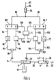
- FIG. 4 The further embodiment of a powder spray coating device according to the invention shown in FIG. 4 is in principle the same as the embodiment shown in FIG. 1, with only two switches 66.1 and 66.2 being provided instead of a single switch 66, one 66.1 each for the conveying air and one 66.2 for the additional air.
- the remaining elements and all functions are the same as in the powder spray coating device of FIG. 1, which is why the same parts are provided with the same reference numerals and details are not described in detail.
- Some identical parts of FIG. 1 are not shown in FIG. 4, but are also present in FIG. 4 in practice.
- the conveying air flows successively through the following elements: internal compressed air inlet 62, total air flow meter 84, compressed air supply line 86, conveying air switch 66.1, manual mode conveying air setting element 68, first OR valve 96, conveying air outlet 14, injector 6, spray device 8.
- Automatic mode flows the Conveying air in succession through the following elements: internal compressed air inlet 62, total air flow meter 84, compressed air supply line 86, conveying air switch 66.1, automatic mode conveying air setting element 78, first or valve 96, conveying air outlet 14, injector 6, spray device 8.
- the additional air flows in Manual operation in succession through the following elements: internal compressed air inlet 62, total air flow meter 84, compressed air supply line 86, additional air switch 66.2, manual operation additional air setting element 72, second OR valve 102, additional air outlet 32, injector 6, spray device 8.
- This additional air flows through one after the other in automatic operation
- OR valves 96 and 102 instead of the two OR valves 96 and 102, other elements can be used which function like a switchable flow switch, by means of which only one of two compressed air inlets can be connected to a compressed air outlet.
- the OR valves 96 and 102, and preferably also other switchable flow switches used instead, are preferably designed such that they are automatically switched by the pressure of the compressed air which flows from an inlet to an outlet of the flow switch to be forwarded, while at the same time the other inlet of the flow switch which can be connected to the outlet is closed.
- the sensor 110 can be designed such that it reports the conveying speed of the objects 24 to the control device 4.
- the connection of the conveying air measuring device 70 (for example for pressure measurement and / or flow velocity measurement and / or measurement of the flow rate per unit of time and / or total flow quantity measurement) to the conveying air outlet 14 or downstream thereof has the advantage that only one such device in total for manual and automatic operation is needed. The same applies to the additional air if a corresponding additional air measuring device 70 is connected to the additional air outlet 32 or downstream thereof.
Abstract
Description
Die Erfindung betrifft eine Pulver-Sprühbeschichtungsvorrichtung gemäß dem Oberbegriff von Anspruch 1.The invention relates to a powder spray coating device according to the preamble of claim 1.
Eine elektrostatische Pulver-Sprühbeschichtungsvorrichtung dieser Art ist aus der EP-B 0 412 489 bekannt. Die bekannte Vorrichtung enthält einen Injektor zur pneumatischen Förderung von Beschichtungspulver von einem Pulverbehälter zu einer Sprühvorrichtung; eine an den Injektor angeschlossene Förderluftleitung, welche mit einem einstellbaren ersten Druckeinstellgerät versehen ist; eine an den Injektor angeschlossene Zusatzgasleitung, welche mit einem einstellbaren zweiten Druckeinstellgerät versehen ist; und eine Gaszufuhrleitung zur Zufuhr von Druckluft zu den beiden Druckeinstellgeräten. In der Gaszufuhrleitung ist ein erstes Durchflußmeßgerät angeordnet, welches die Gesamtluftmenge bestehend aus Förderluft und Zusatzluft angezeigt. Eine zweite Zusatzgasleitung oder Spülluftleitung ist an die Sprühvorrichtung angeschlossen, beispielsweise um von einer Elektrode zur elektrostatischen Aufladung des Pulvers Pulverpartikel abzuhalten, damit sich die Pulverpartikel nicht an der Elektrode festsetzen können. Die Druckeinstellgeräte können einstellbare Druckregler, einstellbare Strömungsdrosseln, einstellbare Hähne oder dergleichen sein. Luft ist das bevorzugte Medium, jedoch können auch andere Gase verwendet werden. Die vom Injektor geförderte Pulvermenge ist abhängig von der dem Injektor zugeführten Förderluftmenge. Die Pulver-Fördermenge ist auch von der Menge der Zusatzluft abhängig, wenn die Zusatzluft in den Unterdruckbereich des Injektors eingeleitet wird. Häufig wird jedoch die Zusatzluft stromabwärts des Unterdruckbereiches dem Förderluft-Pulver-Strom zugeführt. Die Zusatzluft kann deshalb zwei verschiedene Aufgaben erfüllen, nämlich einmal die Pulver-Fördermenge beeinflussen und zum anderen die Strömungsgeschwindigkeit des Pulverstromes stromab des Injektors beeinflussen. Für die Förderung von sehr kleinen Pulvermengen pro Zeiteinheit kann es erforderlich werden, den Förderluftstrom so stark zu reduzieren, daß sich in den Leitungen stromabwärts des Injektors Pulver ablagert. Zur Vermeidung solcher Pulverablagerungen ist in den Leitungen stromabwärts des Injektors eine bestimmte Mindest-Strömungsgeschwindigkeit des Pulver-Luft-Gemisches erforderlich. In diesem Falle kann die Strömungsgeschwindigkeit durch die Zuführung von Zusatzluft erhöht werden. Luft ist zur Förderung des Pulvers erforderlich, jedoch besteht der Nachteil, daß bei einem starken Luftstrom auf ein zu beschichtendes Objekt aufgebrachtes Pulver von dieser Luft wieder weggeblasen wird. Es ist deshalb von Vorteil, nicht nur die für die Förderung einer bestimmten Pulvermenge erforderliche Luft einzustellen, sondern auch darauf zu achten, daß die Gesamtluftmenge innerhalb eines optimalen Bereiches bleibt. Dies wird der Bedienungsperson durch die Beobachtung der Gesamtflußmenge an dem Durchflußmeßgerät ermöglicht, welches in der gemeinsamen Gaszufuhrleitung für die Förderluft und die Zusatzluft angeordnet ist.An electrostatic powder spray coating device of this type is known from EP-B 0 412 489. The known device contains an injector for the pneumatic conveying of coating powder from a powder container to a spraying device; a conveying air line connected to the injector, which is provided with an adjustable first pressure setting device; an additional gas line connected to the injector, which is provided with an adjustable second pressure setting device; and a gas supply line for supplying compressed air to the two pressure setting devices. A first flow meter is arranged in the gas supply line and displays the total amount of air consisting of conveying air and additional air. A second additional gas line or purging air line is connected to the spraying device, for example to prevent powder particles from an electrode for electrostatically charging the powder, so that the powder particles cannot adhere to the electrode. The pressure setting devices can be adjustable pressure regulators, adjustable flow restrictors, adjustable taps or the like. Air is the preferred medium, but other gases can also be used. The amount of powder delivered by the injector depends on the amount of feed air supplied to the injector. The powder flow rate also depends on the amount of additional air if the additional air is introduced into the negative pressure area of the injector. However, the additional air is common fed downstream of the negative pressure area to the conveying air powder stream. The additional air can therefore perform two different tasks, namely influencing the powder flow rate on the one hand and influencing the flow rate of the powder flow downstream of the injector on the other. For the conveyance of very small amounts of powder per unit of time, it may be necessary to reduce the conveying air flow so much that powder is deposited in the lines downstream of the injector. To avoid such powder deposits, a certain minimum flow rate of the powder-air mixture is required in the lines downstream of the injector. In this case, the flow rate can be increased by supplying additional air. Air is required to convey the powder, but there is the disadvantage that powder applied to an object to be coated is blown away again by this air when there is a strong air flow. It is therefore advantageous not only to set the air required for conveying a certain amount of powder, but also to ensure that the total amount of air remains within an optimal range. This is made possible for the operator by observing the total flow on the flow meter, which is arranged in the common gas supply line for the conveying air and the additional air.
Die Sprühvorrichtungen sind vorzugsweise derart ausgebildet, daß mit Ihnen "elektrostatisch" beschichtet werden kann. Dies bedeutet, daß das Pulver elektrostatisch aufgeladen wird, damit es an dem zu beschichtenden Objekt besser haftet, bevor die Pulverschicht anschließend in einem Ofen auf das Objekt aufgeschmolzen wird, und damit weniger Pulverpartikel durch Streuwirkung das Objekt verfehlen. Die elektrostatische Aufladung kann durch Reibung der Pulverpartikel an einer Kanalwand in der Sprühvorrichtung erzeugt werden, sogenannte Reibungselektrizität oder Tribo-Elektrizität, oder durch elektrische Hochspannung an einer Hochspannungselektrode, welche in oder neben dem Strömungsweg des Beschichtungspulvers angeordnet ist und vorzugsweise in oder an der Sprühvorrichtung angeordnet ist. Der Hochspannungserzeuger zur Erzeugung der Hochspannung für die Elektrode kann extern oder innerhalb der Sprühvorrichtung angeordnet werden. Elektrostatische Hochspannungs-Sprühbeschichtungsvorrichtungen sind beispielsweise aus der US-Patentschrift 4 196 465 bekannt.The spray devices are preferably designed such that they are "electrostatic" can be coated. This means that the powder is electrostatically charged so that it adheres better to the object to be coated before the powder layer is subsequently melted onto the object in an oven, and thus fewer powder particles miss the object due to the scattering effect. The electrostatic charge can be generated by friction of the powder particles on a channel wall in the spray device, so-called frictional electricity or triboelectricity, or by high-voltage electricity on a high-voltage electrode, which is arranged in or next to the flow path of the coating powder and preferably arranged in or on the spray device is. The high voltage generator for generating the high voltage for the electrode can be arranged externally or within the spray device. High voltage electrostatic spray coaters are known, for example, from US Pat. No. 4,196,465.
Das Beschichten von Objekten erfolgt normalerweise in Kabinen, durch welche die Objekte hindurchtransportiert werden, und in welche die Sprühvorrichtungen, sogenannte Sprühpistolen, durch Wandöffnungen eingeführt werden.The coating of objects usually takes place in cabins through which the objects are transported and into which the spray devices, so-called spray guns, are inserted through wall openings.
Beim Wechsel von einer Pulversorte auf eine andere Pulversorte, insbesondere bei einem Wechsel der Pulverfarbe, müssen nicht nur sämtliche Strömungswege des Pulvers gereinigt werden, sondern es muß häufig auch die für eine gute Beschichtungsqualität erforderliche Strömungsmenge der Förderluft und der Zusatzluft auf neue optimale Werte eingestellt werden. Ähnliche Einstellungen sind auch erforderlich beim Wechsel von einer Art von Objekten auf eine andere Art von Objekten, sowie bei einer Änderung der Fördergeschwindigkeit der Objekte. Egal welcher der Gründe vorliegt, alle erfordern viel Zeit und eine erfahrene Bedienungsperson, welche anhand von vorgegebenen Tabellen und anhand der visuellen Beobachtung der versprühten Pulverwolke und des Beschichtungsergebnisses die, nach Auffassung der Bedienungsperson, optimalen Werte für die Förderluft und die Zusatzluft einstellt. Dies hat außerdem den Nachteil, daß während dieser Einstellarbeiten Beschichtungspulver verloren geht und von den schlecht beschichteten Objekten das Pulver wieder mit Druckluft abgeblasen werden muß.When changing from one type of powder to another type of powder, in particular when changing the powder color, not only do all of the flow paths of the powder need to be cleaned, but it often has to the flow rate of the conveying air and the additional air required for a good coating quality are also set to new optimal values. Similar settings are also required when changing from one type of object to another type of object, as well as when changing the conveying speed of the objects. No matter which of the reasons, all require a lot of time and an experienced operator who, based on the given tables and the visual observation of the sprayed powder cloud and the coating result, sets the optimum values for the conveying air and the additional air in the operator's opinion. This also has the disadvantage that coating powder is lost during this adjustment work and the powder has to be blown off again with compressed air from the poorly coated objects.
Durch die Erfindung soll die Aufgabe gelöst werden, die Pulver-Sprühbeschichtungsvorrichtung derart auszubilden, daß der für einen Farbwechsel und einen Objektwechsel erforderliche Zeitaufwand reduziert wird.The aim of the invention is to achieve the object of designing the powder spray coating device in such a way that the time required for a color change and an object change is reduced.
Diese Aufgabe wird gemäß der Erfindung durch die Merkmale von Anspruch 1 gelöst.This object is achieved according to the invention by the features of claim 1.
Weitere Merkmale der Erfindung sind in den Unteransprüchen enthalten.Further features of the invention are contained in the subclaims.
Die Erfindung ermöglicht den Betrieb der Pulver-Sprühbeschichtungsvorrichtung wahlweise von Hand oder automatisch und hat folgende Vorteile:The invention enables the powder spray coating device to be operated either manually or automatically and has the following advantages:
Eine Bedienungsperson kann wie beim Stand der Technik die nach seiner Auffassung optimalen Werte für Förderluft und Zusatzluft für die Beschichtung eines bestimmten Objektes von Hand einstellen. Ferner kann, wenn der Automatbetrieb nicht zufriedenstellend arbeitet, jederzeit auf Handbetrieb umgestellt werden. Die von der Bedienungsperson oder bereits vom Hersteller der Pulversprühbeschichtungsvorrichtung ermittelten optimalen Werte für Förderluft und Zusatzluft können für mehrere verschiedene Objekte in der für den Automatbetrieb vorgesehenen Steuervorrichtung gespeichert werden. Bei Automatbetrieb werden die Drücke und Strömungsmengen der Förderluft und der Zusatzluft automatisch von der Steuervorrichtung auf die für das betreffende Objekt optimalen Werte eingestellt, welche in der Steuervorrichtung gespeichert sind. Damit braucht die Bedienungsperson beim Wechsel auf eine andere Pulversorte nicht mehr alle Werte einzeln von Hand einstellen, sondern es ist lediglich nötig, an der Steuervorrichtung die betreffende Pulversorte zu wählen. In gleicher Weise kann bei einem Wechsel auf die Beschichtung eines anderen Objektes die betreffende Objektart und/oder die erforderliche Objekt-Fördergeschwindigkeit an der Steuereinrichtung gewählt werden, welche dann automatisch die richtigen Drücke und Strömungsmengen für die Förderluft und die Zusatzluft einstellt. Wenn man bedenkt, daß eine Sprühbeschichtungsanlage normalerweise mehrere Sprühvorrichtungen hat, jeder Sprühvorrichtung ein eigenes Steuergerät zugeordnet ist, und an jedem Steuergerät für die zugehörige Sprühvorrichtung die Förderluft und die Zusatzluft einzeln eingestellt werden müssen, dann erkennt man leicht, welchen zeitlichen Vorteil die Erfindung hat, durch welche lediglich an der übergeordneten Steuervorrichtung das betreffende Objekt, das betreffende Pulver und/oder die betreffende Objekt-Fördergeschwindigkeit ausgewählt zu werden brauchen. In einer Kabine werden nacheinander häufig verschiedene Arten von Objekten beschichtet. In diesem Falle ermöglicht es die Erfindung, im Transportweg der Objekte einen Objekt-Sensor anzuordnen, welcher mit der Steuervorrichtung verbunden ist und ihr das Vorhandensein und/oder die Art des Objektes meldet. Die Steuervorrichtung kann in Abhängigkeit von diesem Sensorsignal automatisch entsprechende Signale an das Steuergerät für die automatische Einstellung der Förderluft und der Zusatzluft geben. Die Steuervorrichtung ist vorzugsweise computerisiert und enthält Speicher zur Speicherung der für verschiedenen Objekte und/oder verschiedenen Pulversorten und/oder verschiedenen Objekt-Fördergeschwindigkeiten erforderlichen Förderluft-Werte, Zusatzluft-Werte und Fördergeschwindigkeits-Werte. Diese Werte können Drücke und/oder Durchflußmengen und/oder elektrische Spannungen sein.As in the prior art, an operator can manually set what he believes to be the optimum values for conveying air and additional air for coating a specific object. Furthermore, if the automatic mode is not working satisfactorily, it can be switched over to manual mode at any time. The optimal values for conveying air and additional air determined by the operator or already by the manufacturer of the powder spray coating device can be stored for several different objects in the control device provided for automatic operation. In automatic mode, the pressures and flow rates of the conveying air and the additional air are automatically set by the control device to the optimal values for the object in question, which values are stored in the control device. Thus, when changing to a different type of powder, the operator no longer has to set all the values individually by hand, but it is only necessary to select the relevant type of powder on the control device. In the same way, when changing to the coating of another object, the relevant object type and / or the required object conveying speed can be selected on the control device, which then automatically has the correct pressures and flow rates for the conveying air and the additional air. If you consider that a spray coating system normally has several spray devices, each spray device is assigned its own control unit, and the conveying air and the additional air have to be set individually on each control unit for the associated spray device, then it is easy to see the temporal advantage of the invention, by means of which the relevant object, the relevant powder and / or the relevant object conveying speed need only be selected on the higher-level control device. Different types of objects are often coated in succession in a cabin. In this case, the invention makes it possible to arrange an object sensor in the transport path of the objects, which is connected to the control device and reports to it the presence and / or the type of the object. Depending on this sensor signal, the control device can automatically give corresponding signals to the control device for the automatic setting of the conveying air and the additional air. The control device is preferably computerized and contains memories for storing the conveying air values, additional air values and conveying speed values required for different objects and / or different types of powder and / or different object conveying speeds. These values can be pressures and / or flow rates and / or electrical voltages.
Aus der nachfolgenden Beschreibung ist für den Fachmann erkenntlich, daß eine Steuervorrichtung mehrere Steuergeräte steuern kann.From the following description it is clear to the person skilled in the art that one control device can control several control devices.
Die Erfindung wird im folgenden mit Bezug auf die Zeichnungen anhand von mehreren Ausführungsformen als Beispiele beschrieben. In den Zeichnungen zeigen
- Fig. 1.
- schematisch eine Pulver-Sprühbeschichtungsvorrichtung nach der Erfindung,
- Fig. 2
- die Pulver-Sprühbeschichtungsvorrichtung von Fig. 1 bei Handbetrieb, welcher durch gestrichelte Linien gekennzeichnet ist, die den bei Handbetrieb Druckluft führenden Leitungen hinzugefügt sind,
- Fig. 3
- die Pulver-Sprühbeschichtungsvorrichtung von Fig. 1 bei Automatbetrieb, welcher durch gestrichelte Linien gekennzeichnet ist, die den bei Automatbetrieb Druckluft führenden Leitungen hinzugefügt sind,
- Fig. 4
- schematisch eine weitere Ausführungsform einer Pulver-Sprühbeschichtungsvorrichtung nach der Erfindung.
- Fig. 1.
- schematically a powder spray coating device according to the invention,
- Fig. 2
- 1 in manual mode, which is characterized by dashed lines which are added to the lines carrying compressed air in manual mode,
- Fig. 3
- 1 in automatic mode, which is identified by dashed lines which are added to the lines carrying compressed air in automatic mode,
- Fig. 4
- schematically shows a further embodiment of a powder spray coating device according to the invention.
Die in Fig. 1 dargestelle Pulver-Sprühbeschichtungsvorrichtung nach der Erfindung enthält folgende Teile: ein Steuergerät 2; eine elektronische Steuervorrichtung 4; einen als pneumatische Pumpe wirkenden Injektor 6 eine Pulver-Sprühvorrichtung 8; eine Kabine 10.The powder spray coating device according to the invention shown in FIG. 1 contains the following parts: a control unit 2; a electronic control device 4; an
Eine Förderluftleitung 12 verbindet einen Förderluftauslaß 14 des Steuergerätes 2 mit einem Förderlufteinlaß 15 des Injektors 6. Die Förderluft 15 erzeugt im Injektor 6 einen Unterdruck, welcher über eine Saugleitung 16 Beschichtungspulver aus einem Pulverbehälter 18 in den Förderluftstrom saugt und zusammen mit ihm über eine Pulverleitung 20 der Sprühvorrichtung 8 zugeführt wird, welche das Pulver 22 in der Kabine 10 auf ein zu beschichtendes Objekt 24 sprüht. Das Objekt 24 wird von einer Fördervorrichtung 25, an welcher es hängt, durch Wandöffnungen 26 der Kabine 10 transportiert.A conveying
Zur Einstellung der vom Förderluftstrom geförderten Pulvermenge und/oder zur Einstellung einer Gesamtluftmenge in der Pulverleitung 20, welche für gute Beschichtungsqualität optimal ist, kann dem Injektor 6 in seinen Unterdruckbereich 28 oder stromabwärts davon Zusatzluft von einer Zusatzluftleitung 30 zugeführt werden, welche einen Zusatzluftauslaß 32 des Steuergeräts 2 mit einem Zusatzlufteinlaß 33 des Injektors 6 strömungsmäßig verbindet.To adjust the amount of powder conveyed by the conveying air flow and / or to adjust a total amount of air in the
Das Pulver kann in der Sprühvorrichtung 8 entweder durch Reibung an einer Kanalwand oder, entsprechend Fig. 1 durch die Hochspannung einer Hochspannungselektrode 34 elektrostatisch aufgeladen werden, welche in der Sprühvorrichtung 8 im Strömungsweg des Pulvers angeordnet ist und von einem in die Sprühvorrichtung 8 integrierten Hochspannungserzeuger 36 Hochspannung erhält. Der Hochspannungserzeuger 36 erhält seine Niederspannungs-Versorungsspannung über eine elektrische Leitung 38, welche an ein einstellbares Potentiometer 40 des Steuergerätes 2 angeschlossen ist, so daß durch Verstellung des Potentiometers 40 die Hochspannung 34 ein- und ausgeschaltet sowie eingestellt werden kann.The powder can in the
Damit die Pulverpartikel an der Hochspannungselektrode 34 nicht haften und gegebenenfalls auch zur Übertragung von elektrischen Ladungen von der Hochspannungselektrode in den Pulverstrom, wird sie von Elektrodenluft einer Elektrodenluftleitung 42 umströmt, welche einen Elektrodenluftauslaß 44 des Steuergerätes 2 mit einem Elektrodenlufteinlaß 45 der Sprühvorrichtung 8 strömungsmäßig verbindet.So that the powder particles do not adhere to the high-
Das Steuergerät 2 enthält in einem Gehäuse 46 zusätzlich zu dem Potentiometer 40 und den Druckluftauslässen 14, 32, 44: einen Druckluft-Zuleitungsanschluß 48, welcher über ein Druckeinstellelement 49, beispielsweise ein einstellbarer Druckregler oder ein einstellbares Druckreduzierventil, und ein Magnetventil 60 mit einem Druckluftauslaß dieses Magnetventils 60 verbindbar ist, wobei dieser Druckluftauslaß den internen Drucklufteinlaß 62 des Steuergeräts 2 bildet und immer nur dann mit dem Druckluft-Zuleitungsanschluß 48 strömungsmäßig verbunden ist, wenn das Magnetventil 60 von einem Hauptschalter 64 des Steuergerätes 2 eingeschaltet wird, wobei der Hauptschalter 64 gleichzeitig auch die Stromversorgung zu dem Potentiometer 40 einschaltet oder beim Abschalten des Magnetventils 60 gleichzeitig auch die Stromversorgung zum Potentiometer 40 abschaltet; einen Umschalter 66; ein von Hand einstellbares erstes Förderlufteinstellelement 68 in Form eines einstellbaren Druckreglers oder einer einstellbaren Strömungsdrossel; ein an den Förderluftauslaß 14 oder stromabwärts davon strömungsmäßig angeschlossenes Förderluftmeßgerät 70 (z.B. Druckmeßgerät und/oder Durchflußmeßgerät); ein von Hand einstellbares Zusatzlufteinstellelement 72 in Form eines einstellbaren Druckreglers, einer einstellbaren Strömungsdrossel, Proportionalregler oder Proportionalventil; ein automatisch oder ferngesteuert einstellbares zweites Förderlufteinstellelement 78 in Form eines einstellbaren Druckreglers oder einer einstellbaren Strömungsdrossel; ein ferngesteuertes oder automatisches erstes Zusatzlufteinstellelement 82; ein Gesamtluft-Druckflußmeßgerät 84, vorzugsweise ein Schwebekörper-Durchflußmeßgerät, in einer Druckluftzuleitung 86 zur Messung der Gesamtdruckluft bestehend aus Förderluft und Zusatzluft, welche vom internen Drucklufteinlaß 62 über die Druckluftzuleitung 86 zu einem Drucklufteinlaß "P" des Umschalters 66 strömt; ein Elektrodenluft-Einstellelement 88 in Form eines einstellbaren Druckreglers oder einer einstellbaren Strömungsdrossel; und ein Elektrodenluft-Durchflußmeßgerät 90, vorzugsweise ebenfalls ein Schwebekörper-Durchflußmeßgerät.In a housing 46, the control device 2 contains, in addition to the potentiometer 40 and the compressed air outlets 14, 32, 44: a compressed air supply connection 48 which is connected via a pressure setting element 49, for example an adjustable pressure regulator or an adjustable pressure reducing valve, and a solenoid valve 60 with a compressed air outlet of this solenoid valve 60 can be connected, this compressed air outlet forming the internal compressed air inlet 62 of the control unit 2 and always is only fluidly connected to the compressed air supply line connection 48 when the solenoid valve 60 is switched on by a main switch 64 of the control unit 2, the main switch 64 also simultaneously switching on the power supply to the potentiometer 40 or, when the solenoid valve 60 is switched off, also the power supply at the same time Potentiometer 40 switches off; a switch 66; a manually adjustable first conveying air adjusting element 68 in the form of an adjustable pressure regulator or an adjustable flow restrictor; a conveying air meter 70 (e.g., pressure meter and / or flow meter) fluidly connected to or downstream of the conveying air outlet 14; a manually adjustable additional air setting element 72 in the form of an adjustable pressure regulator, an adjustable flow restrictor, proportional regulator or proportional valve; an automatically or remotely adjustable second delivery air setting element 78 in the form of an adjustable pressure regulator or an adjustable flow restrictor; a remote-controlled or automatic first auxiliary air setting element 82; a total air pressure flow meter 84, preferably a variable area flow meter, in a compressed air supply line 86 for measuring the total compressed air consisting of conveying air and additional air which flows from the internal compressed air inlet 62 via the compressed air supply line 86 to a compressed air inlet "P" of the switch 66; an electrode air adjusting element 88 in the form of an adjustable pressure regulator or one adjustable flow restrictor; and an electrode air flow meter 90, preferably also a variable area flow meter.
Der Umschalter 66 kann von Hand oder ferngesteuert von der elektronischen (oder pneumatischen oder hydraulischen) Steuervorrichtung 4 wahlweise zwischen einer Handbetrieb-Stellung und einer Automatikbetrieb-Stellung umgeschaltet werden. Der Umschalter 66 verbindet seinen Drucklufteinlaß "P" in der Handbetrieb-Stellung mit einem Druckluftauslaß "H", und in seiner Automatikbetrieb-Stellung mit einem Druckluftauslaß "A". Ein Elektrodenluft-Strömungsweg 92 führt vom internen Drucklufteinlaß 62 über den Elektrodenluft-Durchflußmesser 90 und danach über das Elektrodenluft-Einstellelement 88 zum Elektrodenluft-Auslaß 44, unabhängig von dem Umschalter 66. Gemäß einer nicht dargestellten anderen Ausführungsform könnte die Elektrodenluft auch über den Umschalter 66 geführt werden und dann vom Umschalter 66 einschaltbar und ausschaltbar sein.The
Ein erster Förderluftweg 94 führt von einer Handbetrieb-Druckluftleitung 95, welche an den Handbetrieb-Druckluftauslaß "H" des Umschalters 66 angeschlossen ist, über das Hand-Förderlufteinstellelement 68 und ein erstes Oder-Ventil 96 zum Förderluftauslaß 14. Ein zweiter Förderluftweg 98 für Automatikbetrieb führt vom Automatik-Druckluftauslaß "A" des Umschalters 66 über eine Automatikbetrieb-Druckluftleitung 99 zum Automatik-Förderlufteinstellelement 78 und dann über das erste Oder-Ventil 96 zum Förderluftauslaß 14. Das erste Oder-Ventil 96 wird vom Förderluftdruck automatisch umgeschaltet, so daß es von den beiden Förderluftwegen 94 und 98 jeweils nur den Förderluftweg mit dem Förderluftauslaß 14 verbindet, in welchem Förderluft zugeführt wird, während das Oder-Ventil 96 gleichzeitig den Einlaß des betreffenden anderen Förderluftweges 98 oder 94 verschließt.A first
Ein erster Zusatzluftweg 100 für Handbetrieb führt von der Handbetriebs-Druckluftleitung 95, welche an den Handbetrieb-Druckluftauslaß "H" des Umschalters 66 angeschlossen ist, über das erste Zusatzluft-Einstellelement 72 für Handbetrieb zu einem ersten Drucklufteinlaß eines zweiten Oder-Ventils 102 und von dessen Druckluftauslaß zum Zusatzluftauslaß 32. Ein zweiter Zusatzluftweg 104 führt von der Automatikbetrieb-Druckluftleitung 99, welche an den Automatikbetrieb-Druckluftauslaß "A" des Umschalters 66 angeschlossen ist, über das zweite Zusatzlufteinstellelement 82 für Automatikbetrieb zu einem zweiten Drucklufteinlaß des zweiten Oder-Ventils 102 und von dessen Druckluftauslaß ebenfalls zum Zusatzluftauslaß 32. Das zweite Oder-Ventil 102 verbindet jeweils nur denjenigen der beiden Zusatzluftwege 100 oder 104 mit dem Zusatzluftauslaß 32, in welchem Zusatzluft gefördert wird, während dieses zweite Oder-Ventil 102 seinen Drucklufteinlaß für den betreffenden anderen Zusatzluftweg 104 oder 102 verschließt.A first
Dadurch sind zwei verschiedene Betriebsarten möglich, entweder Handbetrieb oder Automatikbetrieb.This allows two different operating modes, either manual or automatic.
Handbetrieb: In Fig. 2 sind die bei Handbetrieb von Druckluft durchströmten Leitungen durch zusätzliche strichpunktierte Linien markiert. Der Umschalter 66 steht auf Handbetrieb, so daß Druckluft vom internen Drucklufteinlaß 62 über die Druckluftzuleitung 86 nur zum Handbetrieb-Druckluftauslaß "H" des Umschalters 66 gelangen kann, jedoch nicht zu dessen Automatikbetrieb-Druckluftauslaß "A". Dadurch strömt die Förderluft nur über das erste Hand-Förderlufteinstellelement 68 zum Förderluftauslaß 14, jedoch nicht über das zweite Automatik-Förderlufteinstellelement 78. Die Zusatzluft strömt nur über das erste Handbetrieb-Zusatzlufteinstellelement 72 zum Zusatzluftauslaß 32, jedoch nicht über das zweite Automatikbetrieb-Zusatzlufteinstellelement 82. Der Umschalter 66 kann von Hand oder durch die übergeordnete Steuervorrichtung 4 von Automatikbetrieb auf Handbetrieb oder umgekehrt eingestellt werden, wobei es möglich ist, den Umschalter 66 von Hand in eine andere Stellung, insbesondere in die Automatikbetriebsstellung umzuschalten, auch wenn die übergeordnete Steuervorrichtung 4 Handbetrieb fordert. Die Grundstellung des Umschalters 66 ist Handbetrieb. Dies ist für den Fall einer Störung der Steuervorrichtung 4 von Vorteil.Manual operation: In FIG. 2, the lines through which compressed air flows in manual operation are marked by additional dash-dotted lines. The
Automatikbetrieb: Bei Automatikbetrieb gemäß Fig. 3 ist der Umschalter 66 auf Automatikbetrieb umgeschaltet, so daß Druckluft vom internen Drucklufteinlaß 62 über die Druckluftzuleitung 86 vom Umschalter-Drucklufteinlaß "P" nur zum Automatikbetrieb-Druckluftauslaß "A" des Umschalters 66 gelangen kann, jedoch nicht zu dessen Handbetrieb-Druckluftauslaß "H". Die bei Automatikbetrieb von Druckluft durchströmten Leitungen sind durch eine ihnen hinzugefügte gestrichelte Linie markiert. Bei Automatikbetrieb kann Förderluft nur über das Automatikbetrieb-Förderlufteinstellelement 78 des zweiten Förderluftweges 98 zum Förderluftauslaß 14 gelangen, jedoch nicht über das Handbetrieb-Förderlufteinstellelement 68 des ersten Förderluftweges 94. Zusatzluft kann nur über das Automatikbetrieb-Zusatzlufteinstellelement 82 des zweiten Zusatzluftweges 104 zum Zusatzluftauslaß gelangen, jedoch nicht durch das Handbetrieb-Zusatzlufteinstellelement 72 des ersten Zusatzluftweges 100. Das Automatikbetrieb-Förderlufteinstellelement 78 ist über eine elektrische (pneumatische oder hydraulische) Leitung 106 an die Steuervorrichtung 4 angeschlossen und wird von ihr gesteuert, um den Druck und die Durchflußmenge der Förderluft einzustellen und/oder zu regeln, in Abhängigkeit von der Art des zu beschichtenden Objektes und/oder von der Art des verwendeten Beschichtungspulvers und/oder der Fördergeschwindigkeit der Objekte. Das Automatikbetrieb-Zusatzlufteinstellelement 82 ist über eine zweite elektrische (pneumatische oder hydraulische) Leitung 108 ebenfalls an die Steuervorrichtung 4 angeschlossen und wird von ihr betätigt und/oder geregelt in Abhängigkeit von der Art und/oder der Fördergeschwindigkeit des zu beschichtenden Objektes und/oder von der Art des verwendeten Beschichtungspulvers. Die verwendete Art des Beschichtungspulvers kann der Steuervorrichtung 4 von Hand eingegeben oder durch ein Computerprogramm von einem internen Speicher abgerufen werden. Die Art des Objektes 24, welches beschichtet werden soll, kann der Elektrodensteuervorrichtung von Hand eingegeben werden oder durch ein Computerprogramm von einem internen Speicher abgerufen werden oder von einem Objekterkennungs-Sensor 110 signalisiert werden, welcher neben dem Bewegungsweg des zu beschichtenden Objektes 24 angeordnet ist und der Steuervorrichtung 4 meldet, ob ein Objekt 24 vorhanden ist und/oder von welcher Art es ist. Die Steuervorrichtung 4 kann ein Computerprogramm enthalten, welches nach einem vorbestimmten Programmablauf den genannten Speichern die Daten abruft, welche für die Beschichtung eines bestimmten Objekts benötigt werden.3, the
Die Sprühvorrichtung 8 kann das Beschichtungspulver durch Düsenwirkung oder durch Verwendung eines Rotationkopfes zerstäuben.The
Anstelle von nur einer Sprühvorrichtung 8 können mehrere Sprühvorrichtungen 8 an den Förderluftauslaß 14, den Zusatzluftauslaß 32 und den Elektrodenluftauslaß 44 angeschlossen sein. Ferner ist es möglich, an die Steuervorrichtung 4 mehrere Steuergeräte 2 anzuschließen, beispielsweise ist in Fig. 1 ein zweites Steuergerät 2.2 schematisch dargestellt, welches gleich ausgebildet ist wie das beschriebene Steuergerät 2 und über entsprechende Leitungen 106.2, 108.2 und 109.2 mit der Steuervorrichtung 4 verbunden ist, um dadurch weitere Sprühvorrichtungen 8 mit Druckluft zu versorgen. Die Umschalter 66 von allen Steuergeräten 2 und 2.2 usw. sind je über einen eigenen Steuerleitungsstrang 109 oder 109.2 usw. mit der Steuervorrichtung 4 verbunden.Instead of only one
Die in Fig. 4 dargestellte weitere Ausführungsform einer Pulversprühbeschichtungsvorrichtung nach der Erfindung ist im Prinzip gleich wie die in Fig. 1 dargestellte Ausführungsform, wobei lediglich anstelle eines einzigen Umschalters 66 zwei Umschalter 66.1 und 66.2 vorgesehen sind, je einer 66.1 für die Förderluft und einer 66.2 für die Zusatzluft. Die übrigen Elemente und alle Funktionen sind gleich wie bei der Pulver-Sprühbeschichtungsvorrichtung von Fig. 1, weshalb gleiche Teile mit gleichen Bezugszahlen versehen sind und Einzelheiten nicht im einzelnen beschrieben werden. Einige identische Teile von Fig.l sind in Fig. 4 nicht dargestellt, jedoch auch in der Praxis bei Fig. 4 vorhanden. Bei Handbetrieb strömt die Förderluft nacheinander durch folgende Elemente: Interner Drucklufteinlaß 62, Gesamtluft-Durchflußmeßgerät 84, Druckluftzuleitung 86, Förderluft-Umschalter 66.1, Handbetrieb-Förderlufteinstellelement 68, erstes Oder-Ventil 96, Förderluft-Auslaß 14, Injektor 6, Sprühvorrichtung 8. Bei Automatikbetrieb strömt die Förderluft nacheinander durch folgende Elemente: Interner Drucklufteinlaß 62, Gesamtluft-Durchflußmeßgerät 84, Druckluftzuleitung 86, Förderluft-Umschalter 66.1, Automatikbetrieb-Förderlufteinstellelement 78, erstes Oder-Ventil 96, Förderluftauslaß 14, Injektor 6, Sprühvorrichtung 8. In ähnlicher Weise strömt die Zusatzluft bei Handbetrieb nacheinander durch folgende Elemente: Interner Drucklufteinlaß 62, Gesamtluft-Durchflußmeßgerät 84, Druckluftzuleitung 86, Zusatzluft-Umschalter 66.2, Handbetrieb-Zuzatzlufteinstellelement 72, zweites Oder-Ventil 102, Zusatzluftauslaß 32, Injektor 6, Sprühvorrichtung 8. Diese Zusatzluft strömt bei Automatikbetrieb nacheinander durch folgende Elemente: Interner Drucklufteinlaß 62, Gesamtluft-Durchflußmeßgerät 84, Druckluftzuleitung 86, Zusatzluft-Umschalter 66.2, Automatikbetriebs-Zusatzlufteinstellelement 82, zweites Oder-Ventil 102, Zusatzluftauslaß 32, Injektor 6, Sprühvorrichtung 8.The further embodiment of a powder spray coating device according to the invention shown in FIG. 4 is in principle the same as the embodiment shown in FIG. 1, with only two switches 66.1 and 66.2 being provided instead of a
Bei allen Ausführungsformen können anstelle der beiden Oder-Ventile 96 und 102 auch andere Elemente verwendet werden, welche wie eine umschaltbare Strömungsweiche funktionieren, durch welche jeweils nur einer von zwei Drucklufteingängen mit einem Druckluftausgang verbunden werden kann. Die Oder-Ventile 96 und 102, und vorzugsweise auch stattdessen verwendete andere umschaltbare Strömungsweichen, sind vorzugsweise derart ausgebildet, daß sie von dem Druck der Druckluft automatisch umgeschaltet werden, welche von einem Einlaß zu einem Auslaß der Strömungsweiche weitergeleitet werden soll, während gleichzeitig der betreffende andere, mit dem Auslaß verbindbare Einlaß der Strömungsweiche, verschlossen wird.In all embodiments, instead of the two OR
Alle elektrischen Elemente, Funktionen und Signale können durch entsprechende pneumatische oder hydraulische Elemente, Funktionen oder Signale ersetzt werden. Der Sensor 110 kann derart ausgebildet sein, daß er der Steuervorrichtung 4 die Fördergeschwindigkeit der Objekte 24 meldet.All electrical elements, functions and signals can be replaced by corresponding pneumatic or hydraulic elements, functions or signals. The
Das Anschließen des Förderluftmeßgerätes 70 (z.B. zur Druckmessung und/oder Strömungsgeschwindigkeitsmessung und/oder Messung der Durchflußrate pro Zeiteinheit und/oder Gesamtdurchfluß-Mengenmessung) an den Förderluftauslaß 14 oder stromabwärts davon hat den Vorteil, daß für Handbetrieb und Automatikbetrieb insgesamt nur ein einziges solches Gerät benötigt wird. Das gleiche gilt für die Zusatzluft, wenn ein entsprechendes Zusatzluftmeßgerät 70 an den Zusatzluftauslaß 32 oder stromabwärts davon angeschlossen wird.The connection of the conveying air measuring device 70 (for example for pressure measurement and / or flow velocity measurement and / or measurement of the flow rate per unit of time and / or total flow quantity measurement) to the conveying
Claims (10)
gekennzeichnet durch einen zweiten Förderluftweg (98), welcher ebenfalls zu dem Förderluftauslaß (14) führt; ein von einer Steuervorrichtung (4) automatisch betätigbares zweites Förderluft-Einstellelement (78) im zweiten Förderluftweg (98); eine Umschaltvorrichtung (66; 66.1, 66.2) zwischen einer Druckluftzuleitung (86) und den beiden Förderluftwegen (94, 98), mit welcher die Druckluftzuleitung (86) wahlweise mit dem ersten Förderluftweg (94) oder dem zweiten Förderluftweg (98) je stromaufwärts ihres Förderluft-Einstellelements (68, 78) verbindbar ist.Powder spray coating device comprising at least one control unit (2, 2.2), which has the following features: a conveying air outlet (14) to which a conveying air line (12) for Supply of conveying air to an injector feed pump (6) can be connected in order to pneumatically convey coating powder to a spray device (8); a first feed air path (94) leading to the feed air outlet (14); a manually operable first conveying air setting element (68) in the first conveying air path (94), by means of which the conveying air to the conveying air outlet (14) can be adjusted with respect to its pressure and / or flow rate per unit of time,
characterized by a second delivery air path (98) which also leads to the delivery air outlet (14); a second conveying air setting element (78) in the second conveying air path (98) which can be automatically actuated by a control device (4); a switching device (66; 66.1, 66.2) between a compressed air supply line (86) and the two conveying air paths (94, 98), with which the compressed air supply line (86) optionally with the first conveying air path (94) or the second conveying air path (98) upstream of it Conveying air adjusting element (68, 78) can be connected.
dadurch gekennzeichnet, daß die Steuereinheit (2, 2.2) ferner enthält: einen Zusatzluftauslaß (32), an welchen über eine Zusatzluftleitung (30) ein Zusatzlufteinlaß (33) der Injektor-Förderpumpe (6) anschließbar ist; einen ersten Zusatzluftweg (100), welcher zum Zusatzluftauslaß (32) führt; ein von Hand einstellbares erstes Zusatzluft-Einstellelement (72) im ersten Zusatzluftweg (100), mit welchem Zusatzluft zum Zusatzluftauslaß bezüglich ihres Druckes und/oder ihrer Strömungsmenge pro Zeiteinheit einstellbar ist; einen zweiten Zusatzluftweg (104), welcher ebenfalls zu dem Zusatzluftauslaß (32) führt; ein von der Steuervorrichtung (4) automatisch betätigbares zweites Zusatzlufteinstellelement (82) im zweiten Zusatzluftweg (104) zur Einstellung der Zusatzluft bezügliches ihres Druckes und/oder ihrer Strömungsmenge pro Zeiteinheit durch die Steuervorrichtung (4); wobei die Umschaltvorrichtung (66; 66.1, 66.2) auch zwischen der Druckluftzuleitung (86) und den beiden Zusatzluftwegen (100, 104) angeordnet ist, um die Druckluftzuleitung (86) wahlweise mit dem ersten Zusatzluftweg (100) oder dem zweiten Zusatzluftweg (104) je stromaufwärts ihrer Zusatzluft-Einstellelemente (72, 82) zu verbinden.Powder spray coating apparatus according to claim 1,
characterized in that the control unit (2, 2.2) further contains: an additional air outlet (32), to which an additional air inlet (33) is connected via an additional air line (30) the injector feed pump (6) can be connected; a first auxiliary air path (100) leading to the auxiliary air outlet (32); a manually adjustable first additional air setting element (72) in the first additional air path (100), with which additional air to the additional air outlet can be adjusted with regard to its pressure and / or its flow rate per unit of time; a second auxiliary air path (104) which also leads to the auxiliary air outlet (32); a second additional air setting element (82) which can be automatically actuated by the control device (4) in the second additional air path (104) for setting the additional air with regard to its pressure and / or its flow rate per unit of time through the control device (4); wherein the switching device (66; 66.1, 66.2) is also arranged between the compressed air supply line (86) and the two additional air paths (100, 104) in order to selectively connect the compressed air supply line (86) with the first additional air path (100) or the second additional air path (104) to connect each upstream of their additional air setting elements (72, 82).
dadurch gekennzeichnet, daß der erste Förderluftweg (94) stromaufwärts seines von Hand einstellbaren ersten Förderluft-Einstellelements (68) an einen ersten Druckluftauslaß (H) für Handbetrieb und der Zusatzluftweg (100) stromaufwärts seines von Hand einstellbaren ersten Zusatzlufteinstellelements (72) ebenfalls an den ersten Druckluftauslaß (H) für Handbetrieb der Umschaltvorrichtung (66) strömungsmäßig angeschlossen sind; daß der zweite Förderluftweg (98) stromaufwärts seines automatisch einstellbaren Förderlufteinstellelements (78) und der zweite Zusatzluftweg (104) stromaufwärts seines automatisch einstellbaren Zusatzlufteinstellelements (82) an einen zweiten Druckluftauslaß (A) für Automatikbetrieb der Umstellvorrichtung (66) strömungsmäßig angeschlossen sind.Powder spray coating apparatus according to claim 2,
characterized in that the first conveying air path (94) upstream of its manually adjustable first conveying air setting element (68) to a first compressed air outlet (H) for manual operation and the Auxiliary air path (100) upstream of its manually adjustable first auxiliary air setting element (72) are also connected in terms of flow to the first compressed air outlet (H) for manual operation of the switching device (66); that the second conveying air path (98) upstream of its automatically adjustable conveying air setting element (78) and the second additional air path (104) upstream of its automatically adjustable additional air setting element (82) are connected in terms of flow to a second compressed air outlet (A) for automatic operation of the changeover device (66).
dadurch gekennzeichnet, daß in der Druckluftzuleitung (86) ein Durchflußmeßgerät (84) zu optischen oder akkustischen Anzeige der Gesamtluft-Strömungmenge pro Zeiteinheit, enthaltend die Förderluft und die Zusatzluft, angeordnet ist.Powder spray coating device according to one of the preceding claims,
characterized in that in the compressed air supply line (86) a flow meter (84) for visual or acoustic display of the total air flow rate per unit time, containing the conveying air and the additional air, is arranged.
dadurch gekennzeichnet, daß die Förderluftwege (94, 98) stromabwärts ihrer Förderlufteinstellelemente (68, 78) über eine von der Förderluft selbsttätig umschaltbare Strömungsweiche (96) alternativ an den Förderluftauslaß (14) anschließbar sind.Powder spray coating device according to one of the preceding claims,
characterized in that the conveying air paths (94, 98) downstream of their conveying air setting elements (68, 78) can alternatively be connected to the conveying air outlet (14) via a flow switch (96) which can be switched over automatically by the conveying air.
dadurch gekennzeichnet, daß die beiden Zusatzluftwege (100, 104) stromabwärts ihrer Zusatzlufteinstellelemente (72, 82) über eine von der Zusatzluft selbst gesteuerte umschaltbare Strömungsweiche alternativ an den Zusatzluftauslaß (32) anschließbar sind.Powder spray coating device according to one of the preceding claims,
characterized in that the two additional air paths (100, 104) downstream of their additional air setting elements (72, 82) can alternatively be connected to the additional air outlet (32) via a switchable flow switch controlled by the additional air.
dadurch gekennzeichnet, daß mindestens zwei der genannten Steuereinheiten (2; 2.2) an die automatische Steuervorrichtung (4) angeschlossen sind, um von ihr gesteuert zu werden.Powder spray coating device according to one of the preceding claims,
characterized in that at least two of said control units (2; 2.2) are connected to the automatic control device (4) in order to be controlled by it.
dadurch gekennzeichnet, daß an die automatische Steuervorrichtung (4) ein Objektsensor (110) zur Wahrnehmung der zu beschichtenden Objekte angeschlossen ist, in Abhängigkeit von dessen Sensorsignalen die Steuervorrichtung (4) die Steuereinheit (2, 2.2) steuert oder regelt.Powder spray coating device according to one of the preceding claims,
characterized in that an object sensor (110) for detecting the objects to be coated is connected to the automatic control device (4), the control device (4) controls or regulates the control unit (2, 2.2) as a function of its sensor signals.
dadurch gekennzeichnet, daß an den Förderluftauslaß (14) ein Förderluftmeßgerät (70) zur Messung der Förderluft sowohl bei Handbetrieb als auch bei Automatikbetrieb angeschlossen ist.Powder spray coating device according to one of the preceding claims,
characterized in that a conveying air measuring device (70) for measuring the conveying air is connected to the conveying air outlet (14) both in manual mode and in automatic mode.
dadurch gekennzeichnet, daß die Umschaltvorrichtung einen Umschalter (66.1) für die Förderluft und einen Umschalter (66.2) für die Zusatzluft aufweist.Powder spray coating apparatus according to claim 1 or 2,
characterized in that the changeover device has a changeover switch (66.1) for the conveying air and a changeover switch (66.2) for the additional air.
Applications Claiming Priority (2)
| Application Number | Priority Date | Filing Date | Title |
|---|---|---|---|
| DE19548607A DE19548607A1 (en) | 1995-12-23 | 1995-12-23 | Powder spray coater |
| DE19548607 | 1995-12-23 |
Publications (2)
| Publication Number | Publication Date |
|---|---|
| EP0780160A1 true EP0780160A1 (en) | 1997-06-25 |
| EP0780160B1 EP0780160B1 (en) | 1999-12-22 |
Family
ID=7781327
Family Applications (1)
| Application Number | Title | Priority Date | Filing Date |
|---|---|---|---|
| EP96115438A Expired - Lifetime EP0780160B1 (en) | 1995-12-23 | 1996-09-26 | Powder spray coating device |
Country Status (5)
| Country | Link |
|---|---|
| US (1) | US5776249A (en) |
| EP (1) | EP0780160B1 (en) |
| AT (1) | ATE187903T1 (en) |
| CA (1) | CA2193192C (en) |
| DE (2) | DE19548607A1 (en) |
Cited By (1)
| Publication number | Priority date | Publication date | Assignee | Title |
|---|---|---|---|---|
| EP0943372A3 (en) * | 1998-03-19 | 2002-05-15 | Peter Ribnitz | Controlled powder flow rate regulator |
Families Citing this family (17)
| Publication number | Priority date | Publication date | Assignee | Title |
|---|---|---|---|---|
| DE19748376A1 (en) | 1997-11-03 | 1999-05-06 | Itw Gema Ag | Method and device for powder spray coating |
| DE19748375A1 (en) | 1997-11-03 | 1999-05-06 | Itw Gema Ag | Method and device for powder spray coating |
| DE19748821A1 (en) * | 1997-11-05 | 1999-05-06 | Itw Gema Ag | Powder spray device |
| DE19838279A1 (en) * | 1998-08-22 | 2000-02-24 | Itw Gema Ag | Powder coating system has an injector stage with air supply controlled by restrictor valves that are coupled to a processor |
| US6112999A (en) | 1998-11-13 | 2000-09-05 | Steelcase Development Inc. | Powder paint system and control thereof |
| US6705545B1 (en) | 1998-11-13 | 2004-03-16 | Steelcase Development Corporation | Quick color change powder paint system |
| US6669780B2 (en) | 2000-10-24 | 2003-12-30 | Illinois Tool Works Inc. | Color change booth |
| US20020046702A1 (en) * | 2000-10-24 | 2002-04-25 | James M. Browning | Powder coating system and method for quick color change |
| JP4688353B2 (en) * | 2001-06-29 | 2011-05-25 | 株式会社吉野工作所 | High frequency induction heating type powder coating equipment |
| US6797066B2 (en) * | 2000-10-24 | 2004-09-28 | Kabushiki Kaisya Yoshino Kosakujo | Apparatus and method for powder coating |
| US6695220B2 (en) | 2001-01-11 | 2004-02-24 | Herman Miller, Inc. | Powder spray coating system |
| JP3863029B2 (en) * | 2002-02-07 | 2006-12-27 | 大成化工株式会社 | Powder coating apparatus and powder coating method on inner surface of container having shoulder |
| DE102004052949A1 (en) * | 2004-10-29 | 2006-05-04 | Nordson Corp., Westlake | Method and device for monitoring flow conditions in a wiring harness |
| DE102011088373A1 (en) * | 2011-12-13 | 2013-06-13 | Robert Bosch Gmbh | Hand color dispenser for use in hand color gun, has color delivery unit applying colorant on workpiece in operating mode, and computing unit changing color delivery of color delivery unit in operating mode |
| US10300504B2 (en) | 2013-07-19 | 2019-05-28 | Graco Minnesota Inc. | Spray system pump wash sequence |
| EP3801924A1 (en) * | 2018-06-06 | 2021-04-14 | Nordson Corporation | Electrostatic dispensing of an anti-microbial coating material |
| KR102649715B1 (en) * | 2020-10-30 | 2024-03-21 | 세메스 주식회사 | Surface treatment apparatus and surface treatment method |
Citations (4)
| Publication number | Priority date | Publication date | Assignee | Title |
|---|---|---|---|---|
| US4284032A (en) * | 1978-11-14 | 1981-08-18 | Gema Ag | Pneumatic conveyor of adjustable conveyance capacity for powdered to granular bulk material |
| US4561380A (en) * | 1984-06-21 | 1985-12-31 | Nordson Corporation | Method and apparatus for powder coating a moving web |
| EP0412289A2 (en) * | 1989-08-11 | 1991-02-13 | ITW Gema AG | Electrostatic spray device |
| EP0636420A2 (en) * | 1993-07-26 | 1995-02-01 | ITW Gema AG | Powder conveying device, in particular for coating powder |
Family Cites Families (12)
| Publication number | Priority date | Publication date | Assignee | Title |
|---|---|---|---|---|
| US3450092A (en) * | 1965-07-08 | 1969-06-17 | Vilbiss Co The De | Color change apparatus |
| US3674205A (en) * | 1971-05-14 | 1972-07-04 | Champion Spark Plug Co | Multiple color paint spray system |
| US4077354A (en) * | 1976-10-07 | 1978-03-07 | Walberg Arvid C | Fast discharge electrostatic coating system |
| JPH0643911B2 (en) * | 1985-09-17 | 1994-06-08 | アイ・ティー・エム株式会社 | Gas carrier powder supply system |
| SU1358998A1 (en) * | 1986-03-11 | 1987-12-15 | Проектный Институт Научно-Производственного Объединения "Лакокраспокрытие" | Installation for automatic application of coatings |
| US4863316A (en) * | 1987-07-01 | 1989-09-05 | The Perkin-Elmer Corporation | Closed loop powder flow regulator |
| DE3721875A1 (en) * | 1987-07-02 | 1989-01-12 | Gema Ransburg Ag | METHOD AND DEVICE FOR A POWDER SPRAY COATING SYSTEM |
| DE9015069U1 (en) * | 1990-11-02 | 1991-01-17 | Bopla Gehaeuse Systeme Gmbh, 4980 Buende, De | |
| ES2115700T3 (en) * | 1992-07-08 | 1998-07-01 | Nordson Corp | APPARATUS AND PROCEDURES FOR THE APPLICATION OF DISCRETE COVERAGE. |
| CH688989A5 (en) * | 1993-03-26 | 1998-07-15 | Ribnitz Peter | Apparatus for conveying powder |
| DE4312837C1 (en) * | 1993-04-20 | 1994-10-06 | Lancier Masch Peter | Apparatus for flow measurement in compressed air installations and flow measuring device for this |
| US5558713A (en) * | 1994-10-31 | 1996-09-24 | The Procter & Gamble Company | Method and apparatus for forming a pulsed stream of particles for application to a fibrous web |
-
1995
- 1995-12-23 DE DE19548607A patent/DE19548607A1/en not_active Withdrawn
-
1996
- 1996-09-26 EP EP96115438A patent/EP0780160B1/en not_active Expired - Lifetime
- 1996-09-26 DE DE59603977T patent/DE59603977D1/en not_active Expired - Fee Related
- 1996-09-26 AT AT96115438T patent/ATE187903T1/en not_active IP Right Cessation
- 1996-12-17 CA CA002193192A patent/CA2193192C/en not_active Expired - Fee Related
- 1996-12-20 US US08/770,318 patent/US5776249A/en not_active Expired - Fee Related
Patent Citations (4)
| Publication number | Priority date | Publication date | Assignee | Title |
|---|---|---|---|---|
| US4284032A (en) * | 1978-11-14 | 1981-08-18 | Gema Ag | Pneumatic conveyor of adjustable conveyance capacity for powdered to granular bulk material |
| US4561380A (en) * | 1984-06-21 | 1985-12-31 | Nordson Corporation | Method and apparatus for powder coating a moving web |
| EP0412289A2 (en) * | 1989-08-11 | 1991-02-13 | ITW Gema AG | Electrostatic spray device |
| EP0636420A2 (en) * | 1993-07-26 | 1995-02-01 | ITW Gema AG | Powder conveying device, in particular for coating powder |
Cited By (1)
| Publication number | Priority date | Publication date | Assignee | Title |
|---|---|---|---|---|
| EP0943372A3 (en) * | 1998-03-19 | 2002-05-15 | Peter Ribnitz | Controlled powder flow rate regulator |
Also Published As
| Publication number | Publication date |
|---|---|
| DE19548607A1 (en) | 1997-06-26 |
| ATE187903T1 (en) | 2000-01-15 |
| EP0780160B1 (en) | 1999-12-22 |
| CA2193192A1 (en) | 1997-06-24 |
| CA2193192C (en) | 2000-02-22 |
| US5776249A (en) | 1998-07-07 |
| DE59603977D1 (en) | 2000-01-27 |
Similar Documents
| Publication | Publication Date | Title |
|---|---|---|
| EP0780160B1 (en) | Powder spray coating device | |
| EP0412289B1 (en) | Electrostatic spray device | |
| EP1104334B1 (en) | Powder spray coating device | |
| EP0823286B1 (en) | Injector arrangement for transporting particulate materials | |
| DE4325044C2 (en) | Powder conveying device, in particular for coating powder | |
| DE3030762A1 (en) | DEVICE AND METHOD FOR ELECTROSTATIC POWDER COATING | |
| CH620600A5 (en) | ||
| DE10203580A1 (en) | Method and device for applying particles to surfaces | |
| EP0913203B1 (en) | Method and apparatus for powder coating with purging air supply | |
| DE19519092A1 (en) | Pneumatic powder=feed device | |
| DE3211712A1 (en) | DEVICE FOR SUPPLYING A THERMAL SPRAYING SYSTEM WITH POWDERED SUBSTANCES | |
| EP1115498B1 (en) | Manual spray coating gun | |
| DE2819302A1 (en) | Assembly line vehicle body paint spray equipment - has common control pipes for all paint pressure controls within one another | |
| DE4300832A1 (en) | Powder spray coater | |
| EP0763385B1 (en) | Method for transporting a powdry material by means of an injection | |
| EP0767006A1 (en) | Method and apparatus for feeding powder to a powder spraying device | |
| DE19748376A1 (en) | Method and device for powder spray coating | |
| EP1104335A1 (en) | Powder spray coating device | |
| EP1240947A1 (en) | Powder spray device for coating powder | |
| EP1115499B1 (en) | Powder coating device | |
| EP0455111A1 (en) | Plant for coating series of work pieces with conductive coating material | |
| DE10003077C2 (en) | Device and method for electrostatic powder coating of workpieces with different powders | |
| DE2849261C2 (en) | Method and device for spray-coating objects with powder | |
| WO2004106066A1 (en) | Device for applying powder to moving printed sheets | |
| DE10301508A1 (en) | System for electrostatic powder coating with powder container from which run powder conveying lines to spray guns across injectors |
Legal Events
| Date | Code | Title | Description |
|---|---|---|---|
| PUAI | Public reference made under article 153(3) epc to a published international application that has entered the european phase |
Free format text: ORIGINAL CODE: 0009012 |
|
| 17P | Request for examination filed |
Effective date: 19960926 |
|
| AK | Designated contracting states |
Kind code of ref document: A1 Designated state(s): AT CH DE LI |
|
| RAP3 | Party data changed (applicant data changed or rights of an application transferred) |
Owner name: ITW GEMA AG |
|
| GRAG | Despatch of communication of intention to grant |
Free format text: ORIGINAL CODE: EPIDOS AGRA |
|
| 17Q | First examination report despatched |
Effective date: 19990210 |
|
| GRAG | Despatch of communication of intention to grant |
Free format text: ORIGINAL CODE: EPIDOS AGRA |
|
| GRAH | Despatch of communication of intention to grant a patent |
Free format text: ORIGINAL CODE: EPIDOS IGRA |
|
| GRAH | Despatch of communication of intention to grant a patent |
Free format text: ORIGINAL CODE: EPIDOS IGRA |
|
| GRAA | (expected) grant |
Free format text: ORIGINAL CODE: 0009210 |
|
| AK | Designated contracting states |
Kind code of ref document: B1 Designated state(s): AT CH DE LI |
|
| REF | Corresponds to: |
Ref document number: 187903 Country of ref document: AT Date of ref document: 20000115 Kind code of ref document: T |
|
| REG | Reference to a national code |
Ref country code: CH Ref legal event code: EP |
|
| REG | Reference to a national code |
Ref country code: CH Ref legal event code: NV Representative=s name: E. BLUM & CO. PATENTANWAELTE |
|
| REF | Corresponds to: |
Ref document number: 59603977 Country of ref document: DE Date of ref document: 20000127 |
|
| PLBE | No opposition filed within time limit |
Free format text: ORIGINAL CODE: 0009261 |
|
| STAA | Information on the status of an ep patent application or granted ep patent |
Free format text: STATUS: NO OPPOSITION FILED WITHIN TIME LIMIT |
|
| 26N | No opposition filed | ||
| PGFP | Annual fee paid to national office [announced via postgrant information from national office to epo] |
Ref country code: DE Payment date: 20010831 Year of fee payment: 6 |
|
| PGFP | Annual fee paid to national office [announced via postgrant information from national office to epo] |
Ref country code: CH Payment date: 20010903 Year of fee payment: 6 Ref country code: AT Payment date: 20010903 Year of fee payment: 6 |
|
| PG25 | Lapsed in a contracting state [announced via postgrant information from national office to epo] |
Ref country code: AT Free format text: LAPSE BECAUSE OF NON-PAYMENT OF DUE FEES Effective date: 20020926 |
|
| PG25 | Lapsed in a contracting state [announced via postgrant information from national office to epo] |
Ref country code: LI Free format text: LAPSE BECAUSE OF NON-PAYMENT OF DUE FEES Effective date: 20020930 Ref country code: CH Free format text: LAPSE BECAUSE OF NON-PAYMENT OF DUE FEES Effective date: 20020930 |
|
| PG25 | Lapsed in a contracting state [announced via postgrant information from national office to epo] |
Ref country code: DE Free format text: LAPSE BECAUSE OF NON-PAYMENT OF DUE FEES Effective date: 20030401 |
|
| REG | Reference to a national code |
Ref country code: CH Ref legal event code: PL |