EP0780160A1 - Dispositif de revêtement de poudre par pulvérisation - Google Patents
Dispositif de revêtement de poudre par pulvérisation Download PDFInfo
- Publication number
- EP0780160A1 EP0780160A1 EP96115438A EP96115438A EP0780160A1 EP 0780160 A1 EP0780160 A1 EP 0780160A1 EP 96115438 A EP96115438 A EP 96115438A EP 96115438 A EP96115438 A EP 96115438A EP 0780160 A1 EP0780160 A1 EP 0780160A1
- Authority
- EP
- European Patent Office
- Prior art keywords
- air
- conveying
- additional
- conveying air
- air outlet
- Prior art date
- Legal status (The legal status is an assumption and is not a legal conclusion. Google has not performed a legal analysis and makes no representation as to the accuracy of the status listed.)
- Granted
Links
- 238000005507 spraying Methods 0.000 title claims description 28
- 229940098458 powder spray Drugs 0.000 title claims description 22
- 239000000843 powder Substances 0.000 claims abstract description 49
- 239000007921 spray Substances 0.000 claims description 21
- 239000011248 coating agent Substances 0.000 claims description 16
- 238000000576 coating method Methods 0.000 claims description 16
- 230000000007 visual effect Effects 0.000 claims description 2
- 238000011144 upstream manufacturing Methods 0.000 claims 6
- 239000007789 gas Substances 0.000 description 6
- 239000002245 particle Substances 0.000 description 5
- 230000006870 function Effects 0.000 description 4
- 230000015654 memory Effects 0.000 description 4
- 238000004590 computer program Methods 0.000 description 3
- 238000005259 measurement Methods 0.000 description 3
- 230000005611 electricity Effects 0.000 description 2
- 238000009530 blood pressure measurement Methods 0.000 description 1
- 238000001514 detection method Methods 0.000 description 1
- 230000000694 effects Effects 0.000 description 1
- 239000000203 mixture Substances 0.000 description 1
- 238000010926 purge Methods 0.000 description 1
- 230000001105 regulatory effect Effects 0.000 description 1
- 230000002123 temporal effect Effects 0.000 description 1
Images


Classifications
-
- B—PERFORMING OPERATIONS; TRANSPORTING
- B05—SPRAYING OR ATOMISING IN GENERAL; APPLYING FLUENT MATERIALS TO SURFACES, IN GENERAL
- B05B—SPRAYING APPARATUS; ATOMISING APPARATUS; NOZZLES
- B05B12/00—Arrangements for controlling delivery; Arrangements for controlling the spray area
- B05B12/08—Arrangements for controlling delivery; Arrangements for controlling the spray area responsive to condition of liquid or other fluent material to be discharged, of ambient medium or of target ; responsive to condition of spray devices or of supply means, e.g. pipes, pumps or their drive means
- B05B12/12—Arrangements for controlling delivery; Arrangements for controlling the spray area responsive to condition of liquid or other fluent material to be discharged, of ambient medium or of target ; responsive to condition of spray devices or of supply means, e.g. pipes, pumps or their drive means responsive to conditions of ambient medium or target, e.g. humidity, temperature position or movement of the target relative to the spray apparatus
- B05B12/122—Arrangements for controlling delivery; Arrangements for controlling the spray area responsive to condition of liquid or other fluent material to be discharged, of ambient medium or of target ; responsive to condition of spray devices or of supply means, e.g. pipes, pumps or their drive means responsive to conditions of ambient medium or target, e.g. humidity, temperature position or movement of the target relative to the spray apparatus responsive to presence or shape of target
-
- B—PERFORMING OPERATIONS; TRANSPORTING
- B05—SPRAYING OR ATOMISING IN GENERAL; APPLYING FLUENT MATERIALS TO SURFACES, IN GENERAL
- B05B—SPRAYING APPARATUS; ATOMISING APPARATUS; NOZZLES
- B05B12/00—Arrangements for controlling delivery; Arrangements for controlling the spray area
- B05B12/004—Arrangements for controlling delivery; Arrangements for controlling the spray area comprising sensors for monitoring the delivery, e.g. by displaying the sensed value or generating an alarm
- B05B12/006—Pressure or flow rate sensors
-
- B—PERFORMING OPERATIONS; TRANSPORTING
- B05—SPRAYING OR ATOMISING IN GENERAL; APPLYING FLUENT MATERIALS TO SURFACES, IN GENERAL
- B05B—SPRAYING APPARATUS; ATOMISING APPARATUS; NOZZLES
- B05B12/00—Arrangements for controlling delivery; Arrangements for controlling the spray area
- B05B12/08—Arrangements for controlling delivery; Arrangements for controlling the spray area responsive to condition of liquid or other fluent material to be discharged, of ambient medium or of target ; responsive to condition of spray devices or of supply means, e.g. pipes, pumps or their drive means
- B05B12/085—Arrangements for controlling delivery; Arrangements for controlling the spray area responsive to condition of liquid or other fluent material to be discharged, of ambient medium or of target ; responsive to condition of spray devices or of supply means, e.g. pipes, pumps or their drive means responsive to flow or pressure of liquid or other fluent material to be discharged
-
- B—PERFORMING OPERATIONS; TRANSPORTING
- B05—SPRAYING OR ATOMISING IN GENERAL; APPLYING FLUENT MATERIALS TO SURFACES, IN GENERAL
- B05B—SPRAYING APPARATUS; ATOMISING APPARATUS; NOZZLES
- B05B7/00—Spraying apparatus for discharge of liquids or other fluent materials from two or more sources, e.g. of liquid and air, of powder and gas
- B05B7/14—Spraying apparatus for discharge of liquids or other fluent materials from two or more sources, e.g. of liquid and air, of powder and gas designed for spraying particulate materials
- B05B7/1404—Arrangements for supplying particulate material
-
- B—PERFORMING OPERATIONS; TRANSPORTING
- B05—SPRAYING OR ATOMISING IN GENERAL; APPLYING FLUENT MATERIALS TO SURFACES, IN GENERAL
- B05B—SPRAYING APPARATUS; ATOMISING APPARATUS; NOZZLES
- B05B5/00—Electrostatic spraying apparatus; Spraying apparatus with means for charging the spray electrically; Apparatus for spraying liquids or other fluent materials by other electric means
- B05B5/16—Arrangements for supplying liquids or other fluent material
- B05B5/1683—Arrangements for supplying liquids or other fluent material specially adapted for particulate materials
Definitions
- the invention relates to a powder spray coating device according to the preamble of claim 1.
- An electrostatic powder spray coating device of this type is known from EP-B 0 412 489.
- the known device contains an injector for the pneumatic conveying of coating powder from a powder container to a spraying device; a conveying air line connected to the injector, which is provided with an adjustable first pressure setting device; an additional gas line connected to the injector, which is provided with an adjustable second pressure setting device; and a gas supply line for supplying compressed air to the two pressure setting devices.
- a first flow meter is arranged in the gas supply line and displays the total amount of air consisting of conveying air and additional air.
- a second additional gas line or purging air line is connected to the spraying device, for example to prevent powder particles from an electrode for electrostatically charging the powder, so that the powder particles cannot adhere to the electrode.
- the pressure setting devices can be adjustable pressure regulators, adjustable flow restrictors, adjustable taps or the like. Air is the preferred medium, but other gases can also be used.
- the amount of powder delivered by the injector depends on the amount of feed air supplied to the injector.
- the powder flow rate also depends on the amount of additional air if the additional air is introduced into the negative pressure area of the injector. However, the additional air is common fed downstream of the negative pressure area to the conveying air powder stream. The additional air can therefore perform two different tasks, namely influencing the powder flow rate on the one hand and influencing the flow rate of the powder flow downstream of the injector on the other.
- the spray devices are preferably designed such that they are "electrostatic" can be coated.
- This means that the powder is electrostatically charged so that it adheres better to the object to be coated before the powder layer is subsequently melted onto the object in an oven, and thus fewer powder particles miss the object due to the scattering effect.
- the electrostatic charge can be generated by friction of the powder particles on a channel wall in the spray device, so-called frictional electricity or triboelectricity, or by high-voltage electricity on a high-voltage electrode, which is arranged in or next to the flow path of the coating powder and preferably arranged in or on the spray device is.
- the high voltage generator for generating the high voltage for the electrode can be arranged externally or within the spray device.
- High voltage electrostatic spray coaters are known, for example, from US Pat. No. 4,196,465.
- the coating of objects usually takes place in cabins through which the objects are transported and into which the spray devices, so-called spray guns, are inserted through wall openings.
- the aim of the invention is to achieve the object of designing the powder spray coating device in such a way that the time required for a color change and an object change is reduced.
- an operator can manually set what he believes to be the optimum values for conveying air and additional air for coating a specific object. Furthermore, if the automatic mode is not working satisfactorily, it can be switched over to manual mode at any time.
- the optimal values for conveying air and additional air determined by the operator or already by the manufacturer of the powder spray coating device can be stored for several different objects in the control device provided for automatic operation.
- the pressures and flow rates of the conveying air and the additional air are automatically set by the control device to the optimal values for the object in question, which values are stored in the control device.
- the relevant object type and / or the required object conveying speed can be selected on the control device, which then automatically has the correct pressures and flow rates for the conveying air and the additional air.
- each spray device is assigned its own control unit, and the conveying air and the additional air have to be set individually on each control unit for the associated spray device, then it is easy to see the temporal advantage of the invention, by means of which the relevant object, the relevant powder and / or the relevant object conveying speed need only be selected on the higher-level control device. Different types of objects are often coated in succession in a cabin.
- the invention makes it possible to arrange an object sensor in the transport path of the objects, which is connected to the control device and reports to it the presence and / or the type of the object.
- the control device can automatically give corresponding signals to the control device for the automatic setting of the conveying air and the additional air.
- the control device is preferably computerized and contains memories for storing the conveying air values, additional air values and conveying speed values required for different objects and / or different types of powder and / or different object conveying speeds. These values can be pressures and / or flow rates and / or electrical voltages.
- one control device can control several control devices.
- the powder spray coating device according to the invention shown in FIG. 1 contains the following parts: a control unit 2; a electronic control device 4; an injector 6 acting as a pneumatic pump, a powder spray device 8; a cabin 10.
- a conveying air line 12 connects a conveying air outlet 14 of the control device 2 to a conveying air inlet 15 of the injector 6.
- the conveying air 15 generates a negative pressure in the injector 6, which sucks coating powder from a powder container 18 into the conveying air flow via a suction line 16 and together with it via a powder line 20 is fed to the spraying device 8, which sprays the powder 22 in the booth 10 onto an object 24 to be coated.
- the object 24 is transported by a conveyor device 25, on which it hangs, through wall openings 26 of the cabin 10.
- the injector 6 can be supplied with additional air from an additional air line 30 in its vacuum region 28 or downstream thereof, which has an additional air outlet 32 of the Control unit 2 connects in terms of flow with an additional air inlet 33 of the injector 6.
- the powder can in the spray device 8 either by friction on a channel wall or, according to FIG. 1, by the high voltage of a High voltage electrode 34 are electrostatically charged, which is arranged in the spray device 8 in the flow path of the powder and receives high voltage from a high voltage generator 36 integrated in the spray device 8.
- the high-voltage generator 36 receives its low-voltage supply voltage via an electrical line 38, which is connected to an adjustable potentiometer 40 of the control unit 2, so that the high voltage 34 can be switched on and off and adjusted by adjusting the potentiometer 40.
- electrode air flows around them from an electrode air line 42, which fluidly connects an electrode air outlet 44 of the control device 2 to an electrode air inlet 45 of the spraying device 8.
- the control device 2 contains, in addition to the potentiometer 40 and the compressed air outlets 14, 32, 44: a compressed air supply connection 48 which is connected via a pressure setting element 49, for example an adjustable pressure regulator or an adjustable pressure reducing valve, and a solenoid valve 60 with a compressed air outlet of this solenoid valve 60 can be connected, this compressed air outlet forming the internal compressed air inlet 62 of the control unit 2 and always is only fluidly connected to the compressed air supply line connection 48 when the solenoid valve 60 is switched on by a main switch 64 of the control unit 2, the main switch 64 also simultaneously switching on the power supply to the potentiometer 40 or, when the solenoid valve 60 is switched off, also the power supply at the same time Potentiometer 40 switches off; a switch 66; a manually adjustable first conveying air adjusting element 68 in the form of an adjustable pressure regulator or an adjustable flow restrictor; a conveying air meter 70 (e.g., pressure meter and / or flow meter) fluidly connected to or downstream
- the switch 66 can be switched manually or remotely by the electronic (or pneumatic or hydraulic) control device 4 between a manual mode position and an automatic mode position.
- the change-over switch 66 connects its compressed air inlet "P" in the manual operating position to a compressed air outlet "H", and in its automatic operating position to a compressed air outlet "A".
- An electrode air flow path 92 leads from the internal compressed air inlet 62 via the electrode air flow meter 90 and then via the electrode air adjusting element 88 to the electrode air outlet 44, independently of the switch 66.
- the electrode air could also be via the switch 66 be guided and then be switched on and off by the switch 66.
- a first delivery air path 94 leads from a manual operation compressed air line 95, which is connected to the manual operation compressed air outlet "H" of the switch 66, via the manual delivery air setting element 68 and a first OR valve 96 to the delivery air outlet 14.
- a second delivery air route 98 for automatic operation leads from the automatic compressed air outlet "A" of the switch 66 via an automatic operation compressed air line 99 to Automatic conveying air adjusting element 78 and then via the first OR valve 96 to the conveying air outlet 14.
- the first OR valve 96 is automatically switched by the conveying air pressure, so that it connects only the conveying air path with the conveying air outlet 14 from the two conveying air paths 94 and 98, in which conveying air is supplied, while the OR valve 96 simultaneously closes the inlet of the other conveying air path 98 or 94 in question.
- a first additional air path 100 for manual operation leads from the manual operation compressed air line 95, which is connected to the manual operation compressed air outlet "H" of the switch 66, via the first additional air adjustment element 72 for manual operation to a first compressed air inlet of a second OR valve 102 and from its compressed air outlet to the additional air outlet 32.
- a second additional air path 104 leads from the automatic mode compressed air line 99, which is connected to the automatic mode compressed air outlet "A" of the switch 66, via the second additional air setting element 82 for automatic mode to a second compressed air inlet of the second OR valve 102 and from its compressed air outlet also to the additional air outlet 32.
- the second OR valve 102 connects only that of the two additional air paths 100 or 104 to the additional air outlet 32, in which additional air is conveyed, while this second OR valve 102 has its compressed air inlet for the respective other inlet set airway 104 or 102 closes.
- FIG. 2 the lines through which compressed air flows in manual operation are marked by additional dash-dotted lines.
- the switch 66 is in manual mode, so that compressed air from the internal compressed air inlet 62 can only reach the manual mode compressed air outlet "H" of the switch 66 via the compressed air supply line 86, but not to its automatic mode compressed air outlet "A".
- the conveying air flows only via the first manual conveying air adjusting element 68 to the conveying air outlet 14, but not via the second automatic conveying air adjusting element 78.
- the additional air flows only via the first manual operating auxiliary air adjusting element 72 to the auxiliary air outlet 32, but not via the second automatic operating auxiliary air adjusting element 82
- the changeover switch 66 can be set manually or by the higher-level control device 4 from automatic operation to manual operation or vice versa, it being possible to switch the changeover switch 66 manually into another position, in particular into the automatic operation position, even if the higher-level control device 4 is manual operation demands.
- the basic position of the switch 66 is manual. This is advantageous in the event of a fault in the control device 4.
- the switch 66 is switched to automatic mode, so that compressed air from the internal compressed air inlet 62 via the compressed air supply line 86 from the changeover compressed air inlet "P" can only get to the automatic operation compressed air outlet "A" of the changeover switch 66, but not to its manual operation compressed air outlet "H".
- the lines through which compressed air flows in automatic mode are marked by a dashed line added to them.
- conveying air can only reach the conveying air outlet 14 via the automatic mode conveying air setting element 78 of the second conveying air path 98, but not via the manual mode conveying air setting element 68 of the first conveying air path 94.
- the automatic operating conveying air adjusting element 78 is connected to the control device 4 via an electrical (pneumatic or hydraulic) line 106 and is controlled by it in order to adjust the pressure and the flow rate of the conveying air and / or to regulate, depending on the type of object to be coated and / or on the type of coating powder used and / or the conveying speed of the objects.
- Control device 4 is connected and operated and / or regulated by it depending on the type and / or the conveying speed of the object to be coated and / or on the type of coating powder used.
- the type of coating powder used can be entered into the control device 4 by hand or can be called up from an internal memory by a computer program.
- the type of object 24 to be coated can be entered manually into the electrode control device or can be called up by a computer program from an internal memory or can be signaled by an object detection sensor 110 which is arranged next to the movement path of the object 24 to be coated and the control device 4 reports whether an object 24 is present and / or of what type it is.
- the control device 4 can contain a computer program which, after a predetermined program sequence, calls the said memories the data which are required for the coating of a specific object.
- the spraying device 8 can atomize the coating powder by the action of a nozzle or by using a rotary head.
- a plurality of spray devices 8 can be connected to the conveying air outlet 14, the additional air outlet 32 and the electrode air outlet 44. Furthermore, it is possible to connect several to the control device 4
- a second control device 2.2 is shown schematically in FIG. 1, which is of the same design as the described control device 2 and is connected to the control device 4 via corresponding lines 106.2, 108.2 and 109.2, in order thereby to supply further spray devices 8 with compressed air supply.
- the changeover switches 66 of all control units 2 and 2.2 etc. are each connected to the control device 4 via their own control wiring harness 109 or 109.2 etc.
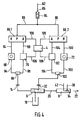
- FIG. 4 The further embodiment of a powder spray coating device according to the invention shown in FIG. 4 is in principle the same as the embodiment shown in FIG. 1, with only two switches 66.1 and 66.2 being provided instead of a single switch 66, one 66.1 each for the conveying air and one 66.2 for the additional air.
- the remaining elements and all functions are the same as in the powder spray coating device of FIG. 1, which is why the same parts are provided with the same reference numerals and details are not described in detail.
- Some identical parts of FIG. 1 are not shown in FIG. 4, but are also present in FIG. 4 in practice.
- the conveying air flows successively through the following elements: internal compressed air inlet 62, total air flow meter 84, compressed air supply line 86, conveying air switch 66.1, manual mode conveying air setting element 68, first OR valve 96, conveying air outlet 14, injector 6, spray device 8.
- Automatic mode flows the Conveying air in succession through the following elements: internal compressed air inlet 62, total air flow meter 84, compressed air supply line 86, conveying air switch 66.1, automatic mode conveying air setting element 78, first or valve 96, conveying air outlet 14, injector 6, spray device 8.
- the additional air flows in Manual operation in succession through the following elements: internal compressed air inlet 62, total air flow meter 84, compressed air supply line 86, additional air switch 66.2, manual operation additional air setting element 72, second OR valve 102, additional air outlet 32, injector 6, spray device 8.
- This additional air flows through one after the other in automatic operation
- OR valves 96 and 102 instead of the two OR valves 96 and 102, other elements can be used which function like a switchable flow switch, by means of which only one of two compressed air inlets can be connected to a compressed air outlet.
- the OR valves 96 and 102, and preferably also other switchable flow switches used instead, are preferably designed such that they are automatically switched by the pressure of the compressed air which flows from an inlet to an outlet of the flow switch to be forwarded, while at the same time the other inlet of the flow switch which can be connected to the outlet is closed.
- the sensor 110 can be designed such that it reports the conveying speed of the objects 24 to the control device 4.
- the connection of the conveying air measuring device 70 (for example for pressure measurement and / or flow velocity measurement and / or measurement of the flow rate per unit of time and / or total flow quantity measurement) to the conveying air outlet 14 or downstream thereof has the advantage that only one such device in total for manual and automatic operation is needed. The same applies to the additional air if a corresponding additional air measuring device 70 is connected to the additional air outlet 32 or downstream thereof.
Landscapes
- Chemical & Material Sciences (AREA)
- Analytical Chemistry (AREA)
- Physics & Mathematics (AREA)
- Fluid Mechanics (AREA)
- Nozzles (AREA)
- Electrostatic Spraying Apparatus (AREA)
- Manufacturing Of Micro-Capsules (AREA)
- Agricultural Chemicals And Associated Chemicals (AREA)
Applications Claiming Priority (2)
| Application Number | Priority Date | Filing Date | Title |
|---|---|---|---|
| DE19548607A DE19548607A1 (de) | 1995-12-23 | 1995-12-23 | Pulver-Sprühbeschichtungsvorrichtung |
| DE19548607 | 1995-12-23 |
Publications (2)
| Publication Number | Publication Date |
|---|---|
| EP0780160A1 true EP0780160A1 (fr) | 1997-06-25 |
| EP0780160B1 EP0780160B1 (fr) | 1999-12-22 |
Family
ID=7781327
Family Applications (1)
| Application Number | Title | Priority Date | Filing Date |
|---|---|---|---|
| EP96115438A Expired - Lifetime EP0780160B1 (fr) | 1995-12-23 | 1996-09-26 | Dispositif de revêtement de poudre par pulvérisation |
Country Status (5)
| Country | Link |
|---|---|
| US (1) | US5776249A (fr) |
| EP (1) | EP0780160B1 (fr) |
| AT (1) | ATE187903T1 (fr) |
| CA (1) | CA2193192C (fr) |
| DE (2) | DE19548607A1 (fr) |
Cited By (1)
| Publication number | Priority date | Publication date | Assignee | Title |
|---|---|---|---|---|
| EP0943372A3 (fr) * | 1998-03-19 | 2002-05-15 | Peter Ribnitz | Régulateur commandé de débit de poudre |
Families Citing this family (17)
| Publication number | Priority date | Publication date | Assignee | Title |
|---|---|---|---|---|
| DE19748375A1 (de) | 1997-11-03 | 1999-05-06 | Itw Gema Ag | Verfahren und Vorrichtung zum Pulver-Sprühbeschichten |
| DE19748376A1 (de) * | 1997-11-03 | 1999-05-06 | Itw Gema Ag | Verfahren und Vorrichtung zum Pulver-Sprühbeschichten |
| DE19748821A1 (de) * | 1997-11-05 | 1999-05-06 | Itw Gema Ag | Pulver-Sprühbeschichtungsvorrichtung |
| DE19838279A1 (de) * | 1998-08-22 | 2000-02-24 | Itw Gema Ag | Pulver-Sprühbeschichtungsvorrichtung |
| US6705545B1 (en) | 1998-11-13 | 2004-03-16 | Steelcase Development Corporation | Quick color change powder paint system |
| US6112999A (en) * | 1998-11-13 | 2000-09-05 | Steelcase Development Inc. | Powder paint system and control thereof |
| US6669780B2 (en) | 2000-10-24 | 2003-12-30 | Illinois Tool Works Inc. | Color change booth |
| US6797066B2 (en) * | 2000-10-24 | 2004-09-28 | Kabushiki Kaisya Yoshino Kosakujo | Apparatus and method for powder coating |
| JP4688353B2 (ja) * | 2001-06-29 | 2011-05-25 | 株式会社吉野工作所 | 高周波誘導加熱式の粉体塗装装置 |
| US20020046702A1 (en) * | 2000-10-24 | 2002-04-25 | James M. Browning | Powder coating system and method for quick color change |
| US6695220B2 (en) | 2001-01-11 | 2004-02-24 | Herman Miller, Inc. | Powder spray coating system |
| JP3863029B2 (ja) * | 2002-02-07 | 2006-12-27 | 大成化工株式会社 | 肩部を有する容器内面への粉体塗装装置並びに粉体塗装方法 |
| DE102004052949A1 (de) * | 2004-10-29 | 2006-05-04 | Nordson Corp., Westlake | Verfahren und Vorrichtung zur Überwachung von Strömungsverhältnissen in einem Leitungsstrang |
| DE102011088373A1 (de) * | 2011-12-13 | 2013-06-13 | Robert Bosch Gmbh | Handfarbabgabevorrichtung |
| US10300504B2 (en) * | 2013-07-19 | 2019-05-28 | Graco Minnesota Inc. | Spray system pump wash sequence |
| WO2019236845A1 (fr) * | 2018-06-06 | 2019-12-12 | Nordson Corporation | Distribution électrostatique d'un matériau de revêtement antimicrobien |
| KR102649715B1 (ko) * | 2020-10-30 | 2024-03-21 | 세메스 주식회사 | 표면 처리 장치 및 표면 처리 방법 |
Citations (4)
| Publication number | Priority date | Publication date | Assignee | Title |
|---|---|---|---|---|
| US4284032A (en) * | 1978-11-14 | 1981-08-18 | Gema Ag | Pneumatic conveyor of adjustable conveyance capacity for powdered to granular bulk material |
| US4561380A (en) * | 1984-06-21 | 1985-12-31 | Nordson Corporation | Method and apparatus for powder coating a moving web |
| EP0412289A2 (fr) * | 1989-08-11 | 1991-02-13 | ITW Gema AG | Dispositif de pulvérisation électrostatique |
| EP0636420A2 (fr) * | 1993-07-26 | 1995-02-01 | ITW Gema AG | Dispositif pour transporter de la poudre, en particulier de la poudre de revêtement |
Family Cites Families (12)
| Publication number | Priority date | Publication date | Assignee | Title |
|---|---|---|---|---|
| US3450092A (en) * | 1965-07-08 | 1969-06-17 | Vilbiss Co The De | Color change apparatus |
| US3674205A (en) * | 1971-05-14 | 1972-07-04 | Champion Spark Plug Co | Multiple color paint spray system |
| US4077354A (en) * | 1976-10-07 | 1978-03-07 | Walberg Arvid C | Fast discharge electrostatic coating system |
| JPH0643911B2 (ja) * | 1985-09-17 | 1994-06-08 | アイ・ティー・エム株式会社 | 気体搬送粉体供給システム |
| SU1358998A1 (ru) * | 1986-03-11 | 1987-12-15 | Проектный Институт Научно-Производственного Объединения "Лакокраспокрытие" | Установка дл автоматического нанесени покрыти "Силуэт |
| US4863316A (en) * | 1987-07-01 | 1989-09-05 | The Perkin-Elmer Corporation | Closed loop powder flow regulator |
| DE3721875A1 (de) * | 1987-07-02 | 1989-01-12 | Gema Ransburg Ag | Verfahren und einrichtung fuer eine pulverspruehbeschichtungsanlage |
| DE9015069U1 (de) * | 1990-11-02 | 1991-01-17 | Bopla Gehäuse Systeme GmbH, 4980 Bünde | Gehäuse für elektrische oder elektronische Bauelemente |
| ES2115700T3 (es) * | 1992-07-08 | 1998-07-01 | Nordson Corp | Aparato y procedimientos para la aplicacion de coberturas discretas. |
| CH688989A5 (de) * | 1993-03-26 | 1998-07-15 | Ribnitz Peter | Vorrichtung zum Fördern von Pulver |
| DE4312837C1 (de) * | 1993-04-20 | 1994-10-06 | Lancier Masch Peter | Vorrichtung zur Strömungsmessung in Druckluftanlagen und Strömungsmeßeinrichtung hierfür |
| US5558713A (en) * | 1994-10-31 | 1996-09-24 | The Procter & Gamble Company | Method and apparatus for forming a pulsed stream of particles for application to a fibrous web |
-
1995
- 1995-12-23 DE DE19548607A patent/DE19548607A1/de not_active Withdrawn
-
1996
- 1996-09-26 EP EP96115438A patent/EP0780160B1/fr not_active Expired - Lifetime
- 1996-09-26 DE DE59603977T patent/DE59603977D1/de not_active Expired - Fee Related
- 1996-09-26 AT AT96115438T patent/ATE187903T1/de not_active IP Right Cessation
- 1996-12-17 CA CA002193192A patent/CA2193192C/fr not_active Expired - Fee Related
- 1996-12-20 US US08/770,318 patent/US5776249A/en not_active Expired - Fee Related
Patent Citations (4)
| Publication number | Priority date | Publication date | Assignee | Title |
|---|---|---|---|---|
| US4284032A (en) * | 1978-11-14 | 1981-08-18 | Gema Ag | Pneumatic conveyor of adjustable conveyance capacity for powdered to granular bulk material |
| US4561380A (en) * | 1984-06-21 | 1985-12-31 | Nordson Corporation | Method and apparatus for powder coating a moving web |
| EP0412289A2 (fr) * | 1989-08-11 | 1991-02-13 | ITW Gema AG | Dispositif de pulvérisation électrostatique |
| EP0636420A2 (fr) * | 1993-07-26 | 1995-02-01 | ITW Gema AG | Dispositif pour transporter de la poudre, en particulier de la poudre de revêtement |
Cited By (1)
| Publication number | Priority date | Publication date | Assignee | Title |
|---|---|---|---|---|
| EP0943372A3 (fr) * | 1998-03-19 | 2002-05-15 | Peter Ribnitz | Régulateur commandé de débit de poudre |
Also Published As
| Publication number | Publication date |
|---|---|
| DE19548607A1 (de) | 1997-06-26 |
| US5776249A (en) | 1998-07-07 |
| ATE187903T1 (de) | 2000-01-15 |
| CA2193192A1 (fr) | 1997-06-24 |
| DE59603977D1 (de) | 2000-01-27 |
| EP0780160B1 (fr) | 1999-12-22 |
| CA2193192C (fr) | 2000-02-22 |
Similar Documents
| Publication | Publication Date | Title |
|---|---|---|
| EP0780160B1 (fr) | Dispositif de revêtement de poudre par pulvérisation | |
| EP0412289B1 (fr) | Dispositif de pulvérisation électrostatique | |
| EP1104334B1 (fr) | Dispositif d'application de revetement en poudre | |
| EP0823286B1 (fr) | Arrangement d'injection pour transporter des matériaux en particules | |
| DE69431169T2 (de) | Pulverbeschichtungssystem | |
| DE69429163T2 (de) | Verfahren und gerät zum beschichten dreidimensionaler artikel | |
| DE3030762A1 (de) | Vorrichtung und verfahren zur elektrostatischen pulverbeschichtung | |
| CH620600A5 (fr) | ||
| DE10203580A1 (de) | Verfahren und Vorrichtung zum Aufbringen von Teilchen auf Oberflächen | |
| EP0636420A2 (fr) | Dispositif pour transporter de la poudre, en particulier de la poudre de revêtement | |
| EP0913203B1 (fr) | Méthode et appareil de revêtement par poudre avec alimentation d'air de purge | |
| DE3211712A1 (de) | Vorrichtung zur versorgung einer thermischen spritzanlage mit pulverfoermigen stoffen | |
| DE2819302C3 (de) | Lackmengen-Steuersystem | |
| DE102007049169A1 (de) | Pulversprühbeschichtungs-Steuergerät und seine Kombination mit einer Pulverfördervorrichtung oder mit einer Pulversprühbeschichtungsvorrichtung | |
| WO2000010723A1 (fr) | Pistolet a commande manuelle pour l'application d'un revetement en poudre | |
| EP0763385B1 (fr) | Procédé de transport d'un matériaux pulvérulent au moyen d'un injecteur | |
| EP0767006A1 (fr) | Méthode et dispositif d'alimentation en poudre d'un appareil de revêtement à poudre | |
| DE19748376A1 (de) | Verfahren und Vorrichtung zum Pulver-Sprühbeschichten | |
| EP1240947A1 (fr) | Dispositif de pulvérisation de poudre pour poudre de revêtement | |
| EP1104335A1 (fr) | Dispositif d'application de revetement en poudre | |
| EP1115499B1 (fr) | Dispositif d'application de revetement en poudre | |
| DE10003077C2 (de) | Einrichtung und Verfahren zum elektrostatischen Pulverbeschichten von Werkstücken mit unterschiedlichen Pulvern | |
| DE2849261C2 (de) | Verfahren und Einrichtung zum Sprühbeschichten von Gegenständen mit Pulver | |
| DE10325386B4 (de) | Vorrichtung zum Aufbringen von Puder auf bewegte Druckbogen | |
| DE10301508A1 (de) | Vorrichtung zur elektrostatischen Pulverbeschichtung |
Legal Events
| Date | Code | Title | Description |
|---|---|---|---|
| PUAI | Public reference made under article 153(3) epc to a published international application that has entered the european phase |
Free format text: ORIGINAL CODE: 0009012 |
|
| 17P | Request for examination filed |
Effective date: 19960926 |
|
| AK | Designated contracting states |
Kind code of ref document: A1 Designated state(s): AT CH DE LI |
|
| RAP3 | Party data changed (applicant data changed or rights of an application transferred) |
Owner name: ITW GEMA AG |
|
| GRAG | Despatch of communication of intention to grant |
Free format text: ORIGINAL CODE: EPIDOS AGRA |
|
| 17Q | First examination report despatched |
Effective date: 19990210 |
|
| GRAG | Despatch of communication of intention to grant |
Free format text: ORIGINAL CODE: EPIDOS AGRA |
|
| GRAH | Despatch of communication of intention to grant a patent |
Free format text: ORIGINAL CODE: EPIDOS IGRA |
|
| GRAH | Despatch of communication of intention to grant a patent |
Free format text: ORIGINAL CODE: EPIDOS IGRA |
|
| GRAA | (expected) grant |
Free format text: ORIGINAL CODE: 0009210 |
|
| AK | Designated contracting states |
Kind code of ref document: B1 Designated state(s): AT CH DE LI |
|
| REF | Corresponds to: |
Ref document number: 187903 Country of ref document: AT Date of ref document: 20000115 Kind code of ref document: T |
|
| REG | Reference to a national code |
Ref country code: CH Ref legal event code: EP |
|
| REG | Reference to a national code |
Ref country code: CH Ref legal event code: NV Representative=s name: E. BLUM & CO. PATENTANWAELTE |
|
| REF | Corresponds to: |
Ref document number: 59603977 Country of ref document: DE Date of ref document: 20000127 |
|
| PLBE | No opposition filed within time limit |
Free format text: ORIGINAL CODE: 0009261 |
|
| STAA | Information on the status of an ep patent application or granted ep patent |
Free format text: STATUS: NO OPPOSITION FILED WITHIN TIME LIMIT |
|
| 26N | No opposition filed | ||
| PGFP | Annual fee paid to national office [announced via postgrant information from national office to epo] |
Ref country code: DE Payment date: 20010831 Year of fee payment: 6 |
|
| PGFP | Annual fee paid to national office [announced via postgrant information from national office to epo] |
Ref country code: CH Payment date: 20010903 Year of fee payment: 6 Ref country code: AT Payment date: 20010903 Year of fee payment: 6 |
|
| PG25 | Lapsed in a contracting state [announced via postgrant information from national office to epo] |
Ref country code: AT Free format text: LAPSE BECAUSE OF NON-PAYMENT OF DUE FEES Effective date: 20020926 |
|
| PG25 | Lapsed in a contracting state [announced via postgrant information from national office to epo] |
Ref country code: LI Free format text: LAPSE BECAUSE OF NON-PAYMENT OF DUE FEES Effective date: 20020930 Ref country code: CH Free format text: LAPSE BECAUSE OF NON-PAYMENT OF DUE FEES Effective date: 20020930 |
|
| PG25 | Lapsed in a contracting state [announced via postgrant information from national office to epo] |
Ref country code: DE Free format text: LAPSE BECAUSE OF NON-PAYMENT OF DUE FEES Effective date: 20030401 |
|
| REG | Reference to a national code |
Ref country code: CH Ref legal event code: PL |