EP0765526B1 - Zusammensetzung auf polymerbasis zur herstellung von magnetischen und magnetisierbaren formkörpern - Google Patents
Zusammensetzung auf polymerbasis zur herstellung von magnetischen und magnetisierbaren formkörpern Download PDFInfo
- Publication number
- EP0765526B1 EP0765526B1 EP95923302A EP95923302A EP0765526B1 EP 0765526 B1 EP0765526 B1 EP 0765526B1 EP 95923302 A EP95923302 A EP 95923302A EP 95923302 A EP95923302 A EP 95923302A EP 0765526 B1 EP0765526 B1 EP 0765526B1
- Authority
- EP
- European Patent Office
- Prior art keywords
- magnetic
- composition according
- composition
- magnets
- permanent
- Prior art date
- Legal status (The legal status is an assumption and is not a legal conclusion. Google has not performed a legal analysis and makes no representation as to the accuracy of the status listed.)
- Expired - Lifetime
Links
Images


Classifications
-
- H—ELECTRICITY
- H02—GENERATION; CONVERSION OR DISTRIBUTION OF ELECTRIC POWER
- H02K—DYNAMO-ELECTRIC MACHINES
- H02K1/00—Details of the magnetic circuit
- H02K1/02—Details of the magnetic circuit characterised by the magnetic material
-
- C—CHEMISTRY; METALLURGY
- C08—ORGANIC MACROMOLECULAR COMPOUNDS; THEIR PREPARATION OR CHEMICAL WORKING-UP; COMPOSITIONS BASED THEREON
- C08K—Use of inorganic or non-macromolecular organic substances as compounding ingredients
- C08K3/00—Use of inorganic substances as compounding ingredients
- C08K3/02—Elements
- C08K3/08—Metals
-
- H—ELECTRICITY
- H01—ELECTRIC ELEMENTS
- H01F—MAGNETS; INDUCTANCES; TRANSFORMERS; SELECTION OF MATERIALS FOR THEIR MAGNETIC PROPERTIES
- H01F1/00—Magnets or magnetic bodies characterised by the magnetic materials therefor; Selection of materials for their magnetic properties
- H01F1/01—Magnets or magnetic bodies characterised by the magnetic materials therefor; Selection of materials for their magnetic properties of inorganic materials
- H01F1/03—Magnets or magnetic bodies characterised by the magnetic materials therefor; Selection of materials for their magnetic properties of inorganic materials characterised by their coercivity
- H01F1/032—Magnets or magnetic bodies characterised by the magnetic materials therefor; Selection of materials for their magnetic properties of inorganic materials characterised by their coercivity of hard-magnetic materials
- H01F1/04—Magnets or magnetic bodies characterised by the magnetic materials therefor; Selection of materials for their magnetic properties of inorganic materials characterised by their coercivity of hard-magnetic materials metals or alloys
- H01F1/06—Magnets or magnetic bodies characterised by the magnetic materials therefor; Selection of materials for their magnetic properties of inorganic materials characterised by their coercivity of hard-magnetic materials metals or alloys in the form of particles, e.g. powder
- H01F1/08—Magnets or magnetic bodies characterised by the magnetic materials therefor; Selection of materials for their magnetic properties of inorganic materials characterised by their coercivity of hard-magnetic materials metals or alloys in the form of particles, e.g. powder pressed, sintered, or bound together
- H01F1/083—Magnets or magnetic bodies characterised by the magnetic materials therefor; Selection of materials for their magnetic properties of inorganic materials characterised by their coercivity of hard-magnetic materials metals or alloys in the form of particles, e.g. powder pressed, sintered, or bound together in a bonding agent
-
- H—ELECTRICITY
- H01—ELECTRIC ELEMENTS
- H01F—MAGNETS; INDUCTANCES; TRANSFORMERS; SELECTION OF MATERIALS FOR THEIR MAGNETIC PROPERTIES
- H01F1/00—Magnets or magnetic bodies characterised by the magnetic materials therefor; Selection of materials for their magnetic properties
- H01F1/01—Magnets or magnetic bodies characterised by the magnetic materials therefor; Selection of materials for their magnetic properties of inorganic materials
- H01F1/03—Magnets or magnetic bodies characterised by the magnetic materials therefor; Selection of materials for their magnetic properties of inorganic materials characterised by their coercivity
- H01F1/12—Magnets or magnetic bodies characterised by the magnetic materials therefor; Selection of materials for their magnetic properties of inorganic materials characterised by their coercivity of soft-magnetic materials
- H01F1/14—Magnets or magnetic bodies characterised by the magnetic materials therefor; Selection of materials for their magnetic properties of inorganic materials characterised by their coercivity of soft-magnetic materials metals or alloys
- H01F1/20—Magnets or magnetic bodies characterised by the magnetic materials therefor; Selection of materials for their magnetic properties of inorganic materials characterised by their coercivity of soft-magnetic materials metals or alloys in the form of particles, e.g. powder
- H01F1/22—Magnets or magnetic bodies characterised by the magnetic materials therefor; Selection of materials for their magnetic properties of inorganic materials characterised by their coercivity of soft-magnetic materials metals or alloys in the form of particles, e.g. powder pressed, sintered, or bound together
- H01F1/24—Magnets or magnetic bodies characterised by the magnetic materials therefor; Selection of materials for their magnetic properties of inorganic materials characterised by their coercivity of soft-magnetic materials metals or alloys in the form of particles, e.g. powder pressed, sintered, or bound together the particles being insulated
- H01F1/26—Magnets or magnetic bodies characterised by the magnetic materials therefor; Selection of materials for their magnetic properties of inorganic materials characterised by their coercivity of soft-magnetic materials metals or alloys in the form of particles, e.g. powder pressed, sintered, or bound together the particles being insulated by macromolecular organic substances
Definitions
- the invention relates to a polymer-based composition for the production of magnetic and magnetizable Molded articles.
- the composition consists of a permanent magnetic and / or ferromagnetic, metal-containing connection and a polymer. Further objects of the invention are Process for the preparation of this composition, the use the composition, molded parts from this composition and a process for producing these molded parts as well magnetic moldings and process for their manufacture.
- Anisotropic permanent magnets made of metal powders can State of the art manufactured in different ways will.
- permanent magnets of various types their magnetic alignment preferably in the pressing direction or is arranged transversely to the pressing direction.
- Such a method for pressing metal powders for Permanent magnets with a radial preferred direction is only limited use for magnets with low height / diameter ratio, the magnets thus made only have weak magnetic properties.
- pole-oriented ring magnets are also manufactured.
- the process is disadvantageous due to the filling problems, the poor orientation and the appearance of Cracks in the sintered parts.
- Another known process for producing the sintered, anisotropic magnets is the strand-pull process.
- Metal powder first creates a bond between the powder and produced by a polymer and the mass produced in this way Pressing, spraying, calendering or extruding and embossing the preferred direction with mechanical or magnetic Methods further processed.
- anisotropic, plastic-bonded permanent magnets show usually better properties than the isotropic permanent magnets from the same magnetic material and can also have different preferred directions such as axial, diametrical, radial and multi-pole.
- compositions are already from the prior art known, in addition to a permanent magnetic and / or Ferromagnetic, metal-containing compound contain a polymer. These compositions are particularly useful for manufacturing of plastic-bonded permanent magnets or induction magnets used.
- DE-A 29 52 820 describes matrix-bound permanent magnets with highly aligned magnetic particles and their production.
- a hot melt polyamide resin is used as the non-magnetic binder used.
- the granulated mixture of ferrite and Polyamide is placed in an injection molding machine and during exposed to a magnetic field during injection.
- DE-A 27 36 642 also reports on plastic-bound Permanent magnets and a process for their manufacture.
- plastic polystyrene but as a solvent Benzene is used.
- the powdery, permanent magnetic Metal and polystyrene dissolved in benzene are mixed and premagnetized in a magnetic field. After evaporation of the solvent and crushing you get an injectable granulate. This is after the Injection molding finally magnetized.
- Disadvantage of this procedure is that the polymer matrix is dissolved in a solvent is separated in a further processing step must be and is also extremely toxic.
- DE-A 36 26 360 describes a manufacturing process for two- and multi-pole permanent magnets with high magnetic Energy density.
- a permanent magnetic powder is included Polymers such as polyamide, polyurethane, polypropylene, polyethylene or polystyrene in a weight ratio of 1: 1 to 20: 1 mixed and granulated. The resulting granulate is thermoplastic into the desired in a magnetic field Mold injected, the preferred directions desired in the final state be impressed. The parts so sprayed then sintered and possibly further machined. The sintered ones are then magnetized Magnets with respect to the embossed poles.
- EP-A 0 350 781 describes a powdery magnetic Material and a magnet made from it. Doing so a crystalline, thermoplastic resin with high heat resistance applied to magnetic powder.
- a thermoplastic Resin is preferred polyether ether ketone, polyether ketone, Polyphenylene sulfide or polysulfide ketone is used.
- the coated magnetic powders are used of extremely polluting, high-boiling solvents prepared, the solvents in a subsequent Step must be extracted under heating.
- the magnets made by this process have the Disadvantage of being slightly brittle and without pretreatment used magnetic powder to break easily.
- DE-A 26 13 904 describes a process for the production of permanent magnets made of epoxy resin and unsaturated polyester resin.
- the disadvantage of this method is that the so manufactured magnets to prevent corrosion
- Protective layers made of nickel or cadmium must be provided, to diffuse oxygen through the polymer layer prevent.
- compositions from the prior art and manufacturing process for plastic-bonded permanent magnets known.
- the compositions and those made from them Permanent magnets do not have the disadvantage to be dimensionally stable and additional processing steps to make necessary to advantageous material properties to reach.
- the dimensional stability the magnets of the prior art often improve after the magnets have been formed, a sintering process is connected, which then leads to additional dimensional stability.
- Farther some processes use solvents that are toxic on the one hand and on the other hand in a complex manner must be removed again.
- the invention is therefore based on the technical problem a composition of a permanent magnetic and / or ferromagnetic, metal-containing compound and a polymer to provide that in the manufacture of anisotropic permanent magnets and inductive magnets temperature-resistant and dimensionally stable products. Further should in processing the composition of the invention the previously necessary process step of sintering eliminated and worked without the use of solvents will. This is intended to manufacture permanent magnets and inductive magnets are considerably more economical be as this according to the methods of the prior art the compositions described there are currently feasible is.
- the composition consists from 74 to 99 percent by weight of metal-containing compound and 1 to 26 weight percent polymer.
- Polymers selected from the formula I preferably contain polymers selected from the group consisting of poly (C 1 -C 4 ) alkylene terephthalate, polynaphthyl acid amide, polyisophthalic acid amide, polyterephthalic acid amide, polyterephthalic acid hexamethylene diamide or mixtures thereof. Polyethylene terephthalate and / or polybutylene terephthalate are particularly preferred.
- polymers from the Group polyesters, polyester amides, polyphenylene ethers, phenylene ethers, Polyphenylene sulfides, aromatic polyether amides, polyamides and polylactame used.
- modifiers described as component C in DE-A 38 28 690 on pages 4 and 5 can be used as additives.
- These are graft polymers which are graft-polymerized from 5 to 90 parts by weight, preferably from 10 to 70 parts by weight, in particular 15 to 50 parts by weight.
- 0.1 to 10 parts by weight can also be used as grafting monomers.
- acrylic or methacrylic acid ester of tertiary butanol and / or 0.1-30 parts by weight a mixture of styrene or ⁇ -methylstyrene and acrylonitrile, methacrylonitrile or maleic anhydride be grafted onto the rubber base.
- methyl methacrylate are particularly preferred graft monomers and n-butyl acrylate in the ratio of 85:15 to 98: 2 and mixtures thereof with tert-butyl acrylate and / or styrene and acrylonitrile (ratio 72:28).
- Preferred diene rubbers are crosslinked homopolymers and / or copolymers of conjugated C 4 to C 6 dienes.
- Preferred diene is 1,3-butadiene.
- the diene copolymers may, based in addition to the diene radicals up to 20 wt.% Based on the diene copolymer, residues of other ethylenically unsaturated monomers such as styrene, acrylonitrile, esters of acrylic or methacrylic acid with monohydric C 1 to C 4 alcohols such as methyl acrylate, ethyl acrylate, Polymerized methyl methacrylate and ethyl methacrylate included.
- Graft polymers B include, for example Graft polymers made of acrylate rubber with a glass transition temperature below -20 ° C as a graft base and polymerizable ethylenically unsaturated monomers with a glass transition temperature above 25 ° C as graft monomers and with styrene and / or acrylonitrile and / or (meth) acrylic acid alkyl esters grafted polybutadienes, butadiene / styrene copolymers and acrylate rubbers.
- Graft polymers made of acrylate rubber with a glass transition temperature below -20 ° C as a graft base and polymerizable ethylenically unsaturated monomers with a glass transition temperature above 25 ° C as graft monomers and with styrene and / or acrylonitrile and / or (meth) acrylic acid alkyl esters grafted polybutadienes, butadiene / styrene
- Silicone rubbers with graft-active areas those in DE-A 37 04 657, DE-A 37 04 655, DE-A 36 31 540 and DE-A 36 31 539 are used. Similar Modifiers based on silicone rubber are also available in the Technique of the publications DE-A 37 25 576, EP-A 0 235 690, DE-A 38 00 603 and EP-A 0 319 290.
- EP-A 0 233 473 contains elastomeric components such as acrylic acid derivatives with monomers containing epoxy groups as Graft pad described.
- EP-A 0 319 581 describes modifiers from ethylene copolymer with ⁇ , ⁇ -unsaturated carboxylic acid alkyl esters and maleic anhydride.
- EP-A 0 256 461 describes on pages 5 and 6 a series of ethylene-propylene rubbers (EPM rubber) and ethylene-propylene-diene rubbers (EPDM rubbers) and their combination options with other modifiers. The rubbers have a Ratio of ethylene to propylene units of 20:80 preferred 65:35 on.
- EP-A 0 484 737 also describes end group-stabilized Polyoxymethylene polymers, EPM and EPDM rubbers, those with acrylic acid derivatives epoxides, dicarboxylic acids and dicarboxylic acid anhydrides, polymers from styrene derivatives, Grafted acrylic acid derivatives, acrylonitrile and polyenes are. Suitable graft-crosslinking monomers are in US-A 4,148,846.
- EP-A 0 313 862 reports on the use of ethylene vinyl alcohol together with grafted, hydrogenated styrene-ethylene-butylene block copolymer, modified with an unsaturated Dicarboxylic acid or an unsaturated dicarboxylic acid anhydride.
- EP-A 0 389 055 describes the use of epoxy and aromatic vinyl diene vinyl cyanide copolymers containing oxazoline groups or aromatic polyesters as Copolymers described.
- Polyurethanes can also be used as further modifiers, as in EP-A 0 115 846, EP-A 0 115 847, EP-A 0 116 456, EP-A 0 117 664 and EP-A 0 327 384 is mentioned.
- Commercially in the trade Such products are available under the name Desmopan® (manufacturer: Bayer AG) and Elastolan® (manufacturer: Elastogran Polyurethane GmbH).
- Polyfluorinated derivatives of ethylene, Propylene, butylene and vinylens are used. Such Products are commercially available under the name Elastosil® (Manufacturer: Wacker Chemie) available. Modifier too Tetrafluoroethylene (PTFE), molybdenum sulfide, graphite and silanes, available under the name Lubrilon® (manufacturer: Com Alloy) can be used.
- Elastosil® Manufacturer: Wacker Chemie
- Modifier too Tetrafluoroethylene (PTFE), molybdenum sulfide, graphite and silanes available under the name Lubrilon® (manufacturer: Com Alloy) can be used.
- WO-A 93/08234 describes the use of ethyl copolymer ionomers and copolyester urethanes, also as modifiers are suitable.
- the modifiers can in the composition according to the invention in an amount of 0 to 70% by weight, in particular 0 to 40 % By weight, based on the total polymer content.
- polybutylene terephthalate and polyethylene terephthalate are described in plastic handbook, volume VIII, polyester, by Dr. L. Goerden, Carl Hanser Verlag, Kunststoff 1971.
- Polybutylene terephthalate is made from dimethyl terephthalate and 1,4-butanediol;
- Polyethylene terephthalate is made from dimethyl terephthalate and 1,2-ethanediol.
- polyterephthalic acid amide is in the plastics manual VI, polyamides, by Prof. Dr. Vieweg and Dr. A. Müller, Carl Hanser Verlag, Kunststoff 1966.
- Polyterephthalic acid amides are made from terephthalic acid and ⁇ , ⁇ -diamines.
- a preferred polyterephthalic acid hexamethylene diamide is one used with other polyamides such as polyamide 6 or polyamide 66 is polymerized.
- Copolyamides are also from dimethyl terephthalic acid and trimethylhexamethylene diamine or isophthalic acid and hexamethylenediamine in combination with the above-mentioned polyterephthalic acid amides can be used.
- Farther miscible with these polymers of formula I are polydiaminobutane diadipidamide, Polyhexamethylene sebacidamide, polyhexamethylene dodecanamide, Polyaminoundecanamide, polylaurin lactam and polyarylamide from meta-xylylenediamine and adipic acid.
- the composition contains 84 to 92 percent by weight of the permanent magnetic and / or ferromagnetic metal-containing compound and 8 to 16 weight percent Polymer.
- Permanent magnetic and / or ferromagnetic metal-containing connections are preferably permanent magnetic metal alloys and / or ferromagnetic, metal-containing connections. Alloys of the metals selected from the group of aluminum, nickel, cobalt, samarium, neodymium, boron or barium ferrite or strontium ferrite or mixtures thereof are used as the permanently magnetic material. The metals selected from the group consisting of iron, cobalt, nickel, Haussler's manganese alloys or rare earth metals or mixtures thereof are used as ferromagnetic, metal-containing compounds.
- Examples of these compounds include ferrite powders such as BaO ⁇ 6Fe 2 O 3 , MnO ⁇ ZnO ⁇ Fe 2 O 3 , ⁇ -Fe 3 O 4 , PbO ⁇ 6Fe 2 O 3 , SrO ⁇ 6Fe 2 O 3 .
- rare earth compounds with cobalt such as. B. SmCo 5 , PrCo 5 , NdCo 5 , SmPrCo 5 , SmPrNdCo 5 , Sm 2 Co 17 , Pr 2 Co 17 , Sm 2 (Co, Fe, Cu) 17 and Sm 2 (Co, Fe, Cu, M) 17 in which M, Ti, Zr or Hf is used.
- Alloys of rare earths of iron and boron such as Nd 2 Fe 14 B, Nd 2 Fe 12 Co 2 B, Pr 2 Fe 14 B can also be used.
- Fe-Cr-Co magnetic powders, Mn-Al-C magnetic powders, Pt-Co magnetic powders and Pt-Fe magnetic powders are also used.
- the composition according to the invention is produced by Mixing the components, namely the metal-containing compound and the polymer of the formula I and optionally further Additives with subsequent granulation of this mixture.
- the composition according to the invention enables any shape, one or to produce a multi-part shaped piece after magnetization used as a permanent magnet or as an inductive magnet can be.
- the magnetic strength can be in Dependence of the concentration of the metal-containing compound control in the polymer.
- composition according to the invention with conventional polymers in overmolded in a single injection process.
- This way and Molded parts can be produced in this way, some of which can be magnetized Areas and partly from non-magnetizable Areas exist.
- a made from the composition of the invention Molding has all the advantageous properties of the used Plastic, such as high impact strength, good corrosion resistance, lower weight and longer durability. Added to this are the well-known properties of a metallic one Magnets. Thus, from the invention Composition magnets with thermoplastic properties produce the usual magnet due to their simple and inexpensive production method are far superior.
- compositions according to the invention are electrically conductive and thermally conductive and so that they can be used as substitutes for metallic conductors can.
- compositions according to the invention are, for example can be used as a contact tongue for lamp holders, whereby the lamp holder is manufactured using the two-component process becomes.
- Another application is the use as Thermocouple in the form of a self-regulating heating conductor, as a material for electrical shielding from electromagnetic Radiation (electrosmog) and to prevent static Charging.
- thermal conductivity is based on the composition according to the invention as a self-regulating heating conductor for defrosting Antennas, window spray systems, door handles, door locks and sunroof frame and to prevent fogging of exterior and interior mirrors.
- Mirrors based on the composition according to the invention can be produced galvanize, do not require a mirrored glass surface and are self-regulating heating conductors.
- the material can also be used for heat heating in the sensor technology area be used.
- a molded part consisting of the composition according to the invention and a Process for the production of this molded part.
- a molded part from the composition is produced by Mixing and granulating the metal-containing compound and the Polymer and then injection molding the injectable Granules in an injection molding machine at temperatures of 180 up to 350 ° C.
- Plasticizers can be single or double shaft Screw extruder, a kneader (manufacturer Buss), "Farrel Continous Mixer "or other Brabender mills, such as” Banbury mills " or others or Henschel mixers, ball mills and Ribbon blender can be used.
- the composition can therefore be used for permanent magnets and Induction magnets are preferably used.
- Induction magnets are preferably used.
- the manufacture of induction magnets becomes the injection molded one After cooling, provide the molded body with an induction coil.
- the sprayed Molded parts are dimensionally stable, so that so far usual sintering process can be omitted.
- Such magnets can be used in continuous operation at up to 180 ° C. Further omitted in the manufacture and processing of the invention Composition of the use of solvents.
- FIGS 1 to 5 are the applications of the invention Explain the composition in more detail.
- FIG. 1 shows armature and compensation winding of a DC motor, in the case of the plastic-bonded, permanently magnetic mixtures (1), (4), (2) introduced and in a second injection molding process a non-magnetic material these plastic-bound Permanent magnets are encapsulated as a housing (5).
- Figure 2 shows a runner with set bars (2/1) this runner as a single runner (2/2), relay runner (2/3) and double relay (2/4) is sprayed and in a second injection molding of the rotor cage with higher melting, non-magnetic polymer is ejected.
- Figure 3 describes the two-channel or multi-channel injection molding technology. With this method it is possible to use ferromagnetic or permanently magnetic, plastic-bound materials in an injection molding process with non-magnetic materials to overmold.
- the non-magnetizable Material A injection molded and in a subsequent step additionally a magnetizable material B is injection molded.
- a Further injection molding with material B is how material B becomes Material A coated.
- FIG. 4 shows a shift plan for a three-legged core of a transformer.
- the transformer legs can also be used here and cores with ferromagnetic plastics getting produced.
- Number (4/2) shows the first position of the shift schedule, number (4/1) the second layer.
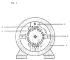
- FIG. 5 shows a shaded-pole motor, the numbers (1), (5) the main pole, the number (2) the gap pole, the number (3) the Short-circuit winding and number (4) denotes the switching pole.
- the permanently magnetically set, plastic-bound mixtures can be admitted according to the current state of the art injection molding any part and can therefore in the most cases all molded and sintered parts Replace magnets, as in DC motors.
- this injection molding technique is that in a second Injection molding with a non-magnetic material, this can any plastic material according to the prior art be the plastic-bonded magnets as the housing can be overmolded (see FIG. 1).
- Magnetic moldings produced in this way can also be used in Electric generators, used in dynamos and in transformers Find.
- Ferromagnetic materials are used as induction magnets of any kind. Examples are given here the rotor in squirrel-cage motors, the rotor with crossed bars as single runners, relay runners, Double relay runners or multiple runners are pre-injected and with the rotor cage in a second injection molding process higher melting, non-magnetic polymer will. Depending on the application, the core injection and then the cage structure injection can be carried out (see Fig.2).
- Injection molding technology is a two-channel or multi-channel technology known, these methods allow ferromagnetic or permanent magnetic materials in one Injection molding process around (see Fig. 3).
- ferromagnetic plastics manufactured in this way can the ferromagnetic particles in a magnetic field be aligned, making the electrical resistance perpendicular to the longitudinal direction of the magnetic field is increased means eddy current losses can be reduced. As well you can use this process to reduce the eddy current losses in the Reduce the housing of a shaded-pole motor (see Figure 5). As well can the polymers filled with metal powder as electrical conductive polymers are used.
- a mixture of 90 parts by weight of anisotropic cobalt-samarium alloy comes with 10 parts by weight Polybutylene terephthalate with a melt flow index (MFI of 250 ° C / 2.16 kg) 47.2 g per 10 minutes on a ZSK 30 (twin-screw extruder by Werner and Pfleiderer) at 300 rpm and 20 kg / h throughput mixed and strand granulated.
- MFI melt flow index
- This injectable granulate is in the injection molding machine at a temperature of 280 to 300 ° C to a molded part injection molded and then after cooling in one Magnetic field magnetized for use as a permanent magnet.
- This injectable granulate is in the injection molding machine a molded part that is used for an induction magnet can be used.
- 14 weight percent polybutylene terephthalate with a Melt flow index (250 ° C / 2.16 kg) of 47.2 g per 10 minutes, 2% by weight of methylbutadiene styrene rubber is 84 Weight percent of a neodymium-iron-boron alloy with one average particle diameter of 8 to 10 ⁇ m in a ZSK 30 (Werner and Pfleiderer twin-screw extruders) at 290 rpm and 21 kg / h throughput mixed and strand granulated.
- This injectable granules become one in the injection molding machine Injection molded part and then in a magnetic field magnetized for use as a permanent magnet.
- a blend of 10 weight percent polybutylene terephthalate with a melt flow index of (250 ° C / 2.16 kg) 47.2 g per 10 Minutes, 10 weight percent polycarbonate as additive, Melt flow index (300 ° C / 1.2 kg) 10 g per 10 minutes and 6 Weight percent modifier Paraloid® EXL 3600 are 74 Weight percent of a neodymium-iron-boron alloy with a average grain size from 10 to 12 pm in a ZSK 30 (twin-screw extruder by Werner and Pfleiderer) at 300 rpm and 20 kg / h throughput mixed and strand granulated.
- the injectable Granules become molded parts in the injection molding machine injection molded and then in a magnetic field for magnetizes the use of permanent magnets.
- example 6 the components are used as in example 5, however mixed on a kneader (manufacturer: Buss), extruded and injection molded.
- a mixture of 90% by weight anisotropic cobalt-samarium alloy, 8% by weight of paraphenylene sulfide and 2 weight percent polybutylene terephthalate is on a kneader (Manufacturer: Buss) or twin-screw extruder mixed and strand granulated.
- This injectable granulate is in the Injection molding machine at a temperature of 320 to 340 ° C too an injection molded part and then after cooling magnetized in a magnetic field.
- Example 7 The components are used as in Example 7, however on a single-screw extruder (manufacturer: Bamag Typ 11.4) extruded and injection molded. You get a molded part, which is magnetized after cooling in a magnetic field.
Description
Claims (18)
- Zusammensetzung enthaltend 45 bis 99 Gew% einer dauermagnetischen und/oder ferromagnetischen metallhaltigen Verbindung in Pulverform und 1 bis 55 Gew% eines Polymers der Formel I,worin R1 gleich Phenyl, Naphtyl, Cyclohexyl, Cyclohexenyl oder ein C1 bis C4 Alkyl-substituiertes Derivat davon ist, und wenn R1 gleich Phenyl ist, die Carboxy-Gruppen in ortho-, meta- oder para-Stellung zueinander stehen,X, Z gleich O oder NR2 sind, wobei R2 gleich H oder C1 bis C4 Alkyl ist,Y gleich (CH2)m oder Phenyl, Cyclohexyl, oder Cyclopentyl ist und m gleich 1 bis 12 ist undn eine ganze Zahl ist.
- Zusammensetzung nach Anspruch 1, dadurch gekennzeichnet, daß sie ein Polymer ausgewählt aus der Gruppe Poly-(C1-C4)alkylenterephthalat, Polynaphtylsäureamid, Polyisophthalsäureamid, Polyterephthalsäureamid, Polyterephthalsäurehexamethylendiamid oder Gemische derselben enthält.
- Zusammensetzung nach Ansprüchen 1 oder 2, dadurch gekennzeichnet, daß sie Polyethylenterephthalat und/oder Polybutylenterephthalat enthält.
- Zusammensetzung nach Ansprüchen 1 bis 3, dadurch gekennzeichnet, daß sie dauerhaft magnetische Metallegierungen und/oder ferromagnetische, metallhaltige Verbindungen enthält.
- Zusammensetzung nach Ansprüchen 1 bis 4, dadurch gekennzeichnet, daß als dauerhaft magnetisches Material Legierungen der Metalle ausgewählt aus der Gruppe Aluminium, Nickel Cobalt, Samarium, Neodym, Bor oder Bariumferrit oder Strontiumferrit oder Gemische derselben enthalten sind.
- Zusammensetzung nach Ansprüchen 1 bis 5, dadurch gekennzeichnet, daß als ferromagnetische metallhaltige Verbindungen die Metalle ausgewählt aus der Gruppe Eisen, Cobalt, Nickel, Heußlersche Manganlegierungen oder Metalle der Seltenen Erden oder Mischungen derselben enthalten sind.
- Zusammensetzung nach Ansprüchen 1 bis 6, dadurch gekennzeichnet, daß dem Polymer der Formel I weitere Polymere aus der Gruppe Polyester, Polyesteramide, Polyphenylenether, Polyphenylensulfide, aromatische Polyetheramide, Polyamide, Polylactame zugesetzt werden.
- Zusammensetzung nach Anspruch 7, dadurch gekennzeichnet, daß Polymere ausgewählt aus der Gruppe Polydiaminobutandiadipidamid, Polyhexamethylensebacidamid, Polyhexamethylendodecanamid, Polyaminoundecanamid, Polylaurinlactam, Polyarylamid oder Gemische derselben zugesetzt werden.
- Zusammensetzung nach Ansprüchen 1 bis 8, dadurch gekennzeichnet, daß die Zusammensetzung 74 bis 99 Gew% metallhaltige Verbindung und 1 bis 26 Gew% Polymer enthält.
- Zusammensetzung nach Ansprüchen 1 bis 9, dadurch gekennzeichnet, daß die Zusammensetzung 84 bis 92 Gew% metallhaltige Verbindung und 8 bis 16 Gew% Polymer enthält.
- Verfahren zur Herstellung der Zusammensetzung gemäß Ansprüchen 1 bis 10, dadurch gekennzeichnet, daß die Komponenten gemischt und granuliert werden.
- Formteil bestehend aus der Zusammensetzung gemäß Ansprüchen 1 bis 10.
- Verfahren zur Herstellung eines Formteils gemäß Anspruch 12, dadurch gekennzeichnet, daß die Komponenten gemischt und granuliert werden und das spritzfähige Granulat in einer Spritzgußmaschine bei einer Temperatur von 180 bis 350°C zu einem Formteil spritzgegossen wird.
- Verfahren nach Anspruch 13, dadurch gekennzeichnet, daß die Komponenten vor dem Spritzgießen auf einem Kneter oder einer ähnlichen Plastifiziermaschine gemischt werden.
- Magnetischer Formkörper bestehend aus der Zusammensetzung gemäß Ansprüchen 1 bis 10.
- Verfahren zur Herstellung eines magnetischen Formkörpers, gemäß Anspruch 15, dadurch gekennzeichnet, daß ein Formteil gemäß Anspruch 13 hergestellt wird und dieses dann in einem Magnetfeld dauerhaft magnetisiert wird.
- Verwendung der Zusammensetzung gemäß Ansprüchen 1 bis 10, für Permanentmagnete und Induktionsmagnete.
- Verwendung nach Anspruch 17, dadurch gekennzeichnet, daß die Magnete als Magnetschalter, Impulsschalter, Magnete in Gleichstrommotoren, in Elektrogeneratoren, in Dynamos, in Transformatoren und als Induktionsmagnete für Läufer in Kurzschlußläufermotoren verwendet werden.
Applications Claiming Priority (3)
| Application Number | Priority Date | Filing Date | Title |
|---|---|---|---|
| DE4420318 | 1994-06-11 | ||
| DE4420318A DE4420318C2 (de) | 1994-06-11 | 1994-06-11 | Zusammensetzung auf Polymerbasis zur Herstellung von magnetischen und magnetisierbaren Formkörpern |
| PCT/EP1995/002256 WO1995034902A1 (de) | 1994-06-11 | 1995-06-12 | Zusammensetzung auf polymerbasis zur herstellung von magnetischen und magnetisierbaren formkörpern |
Publications (2)
| Publication Number | Publication Date |
|---|---|
| EP0765526A1 EP0765526A1 (de) | 1997-04-02 |
| EP0765526B1 true EP0765526B1 (de) | 1998-05-27 |
Family
ID=6520282
Family Applications (1)
| Application Number | Title | Priority Date | Filing Date |
|---|---|---|---|
| EP95923302A Expired - Lifetime EP0765526B1 (de) | 1994-06-11 | 1995-06-12 | Zusammensetzung auf polymerbasis zur herstellung von magnetischen und magnetisierbaren formkörpern |
Country Status (10)
| Country | Link |
|---|---|
| US (1) | US5932134A (de) |
| EP (1) | EP0765526B1 (de) |
| JP (1) | JPH10504423A (de) |
| CN (1) | CN1150495A (de) |
| AT (1) | ATE166744T1 (de) |
| DE (2) | DE4420318C2 (de) |
| DK (1) | DK0765526T3 (de) |
| ES (1) | ES2120216T3 (de) |
| WO (1) | WO1995034902A1 (de) |
| ZA (1) | ZA954764B (de) |
Cited By (1)
| Publication number | Priority date | Publication date | Assignee | Title |
|---|---|---|---|---|
| DE102009010162A1 (de) * | 2009-02-23 | 2010-09-02 | Gangolf Jobb | Elektromaschine für ein Wellenarray |
Families Citing this family (24)
| Publication number | Priority date | Publication date | Assignee | Title |
|---|---|---|---|---|
| DE19526712C2 (de) * | 1995-07-24 | 2000-07-20 | Schulman A Gmbh | Zusammensetzung auf Polymerbasis zur Herstellung von nicht magnetischen metallhaltigen Formkörpern, Verfahren und Verwendung |
| DE19537013A1 (de) * | 1995-10-04 | 1997-06-05 | Schulman A Gmbh | Zusammensetzung auf Polymerbasis und Verfahren zu ihrer Herstellung |
| DE19653178A1 (de) * | 1996-12-19 | 1998-06-25 | Inventa Ag | Thermoplastisch verarbeitbare Formmasse, Verfahren zur Herstellung der Formmasse und Verwendung derselben |
| JP2000036403A (ja) * | 1998-07-21 | 2000-02-02 | Seiko Epson Corp | 希土類ボンド磁石用組成物、希土類ボンド磁石および希土類ボンド磁石の製造方法 |
| DE19910182B4 (de) * | 1999-03-08 | 2013-12-12 | Fraunhofer-Gesellschaft zur Förderung der angewandten Forschung e.V. | Verfahren zur Herstellung und Magnetisierung permanentmagnetischer Folien |
| JP2000348918A (ja) * | 1999-06-02 | 2000-12-15 | Seiko Epson Corp | 希土類ボンド磁石、希土類ボンド磁石用組成物および希土類ボンド磁石の製造方法 |
| CA2282636A1 (en) | 1999-09-16 | 2001-03-16 | Philippe Viarouge | Power transformers and power inductors for low frequency applications using isotropic composite magnetic materials with high power to weight ratio |
| JP3986043B2 (ja) * | 2001-02-20 | 2007-10-03 | 日立粉末冶金株式会社 | 圧粉磁心及びその製造方法 |
| US6737451B1 (en) | 2001-09-13 | 2004-05-18 | Arnold Engineering Co., Ltd. | Thermally stable, high temperature, samarium cobalt molding compound |
| US7504920B2 (en) * | 2001-09-26 | 2009-03-17 | Tekonsha Engineering Company | Magnetic brake assembly |
| US6774171B2 (en) * | 2002-01-25 | 2004-08-10 | L&L Products, Inc. | Magnetic composition |
| DE102004013608A1 (de) * | 2004-03-19 | 2005-10-27 | Siemens Ag | Auslöserelais |
| DE102004054038B4 (de) * | 2004-11-05 | 2008-04-03 | Carl Freudenberg Kg | Permanent magnetische Mischung, Verfahren zu ihrer Herstellung und ihre Verwendung |
| JP4821151B2 (ja) * | 2005-03-25 | 2011-11-24 | 日亜化学工業株式会社 | ボンド磁石 |
| US20100178250A1 (en) * | 2006-08-25 | 2010-07-15 | Philadelphia Health & Education Corporation | Method of Local Delivery of Bioactive and Diagnostic Agents Using Magnetizable Bone Cement |
| DE102007038732A1 (de) * | 2007-08-16 | 2009-02-19 | Continental Automotive Gmbh | Elektronisch kommutierter Motor |
| JP2013544720A (ja) | 2010-10-27 | 2013-12-19 | インターコンチネンタル グレート ブランズ エルエルシー | 磁気的に閉鎖可能な製品収容パッケージ |
| DE102014205675A1 (de) * | 2014-03-26 | 2015-10-01 | Bühler Motor GmbH | Permanentmagnetrotor und Verfahren zur Herstellung eines Permanentmagnetrotors mittels Sandwich-Spritzguss von NdFeB-Magneten |
| JP6813941B2 (ja) * | 2015-02-25 | 2021-01-13 | Dowaエレクトロニクス株式会社 | 磁性コンパウンド、アンテナおよび電子機器 |
| US20170100862A1 (en) | 2015-10-09 | 2017-04-13 | Lexmark International, Inc. | Injection-Molded Physical Unclonable Function |
| CN105585838B (zh) * | 2016-01-18 | 2018-09-07 | 横店集团东磁股份有限公司 | 一种注塑尼龙12-永磁铁氧体颗粒料及制备方法 |
| CN106858860A (zh) * | 2017-01-05 | 2017-06-20 | 迈杰斯蒂国际集团有限公司 | 以多极充磁的柔性磁条为载体的睫毛饰件 |
| GB2580599B (en) * | 2019-01-14 | 2023-06-21 | Sg Tech Limited | Magnetic rotor unit, and apparatus and method of manufacturing a magnetic rotor unit |
| CN112927880A (zh) * | 2021-03-26 | 2021-06-08 | 成都银磁材料有限公司 | 一种注塑永磁铁氧体材料、注塑磁体及其制备方法 |
Family Cites Families (35)
| Publication number | Priority date | Publication date | Assignee | Title |
|---|---|---|---|---|
| US4148846A (en) * | 1970-09-10 | 1979-04-10 | Rohm And Haas Company | Acrylic modifiers for polycarbonamides |
| US4000229A (en) * | 1973-04-26 | 1976-12-28 | Horizons Incorporated | Nucleation and orientation of linear polymers |
| DE2613904A1 (de) * | 1976-03-31 | 1977-10-06 | Siemens Ag | Kunstharzgebundene dauermagnete |
| DE2736642A1 (de) * | 1977-08-13 | 1979-02-15 | Max Baermann | Kunststoffgebundener dauermagnet und verfahren zu seiner herstellung |
| US4200547A (en) * | 1979-01-02 | 1980-04-29 | Minnesota Mining And Manufacturing Company | Matrix-bonded permanent magnet having highly aligned magnetic particles |
| US4327346A (en) * | 1979-02-28 | 1982-04-27 | Tdk Electronics Co., Ltd. | Anisotropic polymeric magnet in the tubular form and process for producing the same |
| JPS5932107A (ja) * | 1982-08-16 | 1984-02-21 | Seiko Epson Corp | 複合軟磁性材料 |
| DE3303760A1 (de) * | 1983-02-04 | 1984-08-09 | Hoechst Ag, 6230 Frankfurt | Schlagzaeh modifiziertes polyoxymethylen und daraus hergestellte formkoerper |
| DE3303761A1 (de) * | 1983-02-04 | 1984-08-09 | Hoechst Ag, 6230 Frankfurt | Schlagzaeh modifiziertes polyoxymethylen und daraus hergestellte formkoerper |
| CA1278395C (en) * | 1983-02-07 | 1990-12-27 | E. I. Du Pont De Nemours And Company | Toughened polyoxymethylene compositions |
| CA1341215C (en) * | 1983-02-07 | 2001-04-24 | Edmund Arthur Flexman, Jr. | Impact resistant polyoxymethylene compositions |
| DE3601422A1 (de) * | 1986-01-20 | 1987-07-23 | Basf Ag | Thermoplastische formmassen auf der basis von polycarbonaten und polyestern |
| JP2632803B2 (ja) * | 1986-03-03 | 1997-07-23 | ポリプラスチックス 株式会社 | 電動機ローター |
| DE3606982A1 (de) * | 1986-03-04 | 1987-09-10 | Bayer Ag | Pfropfpolymerisate auf kautschukpolymeren mit blockartiger struktur |
| DE3626360C2 (de) * | 1986-08-04 | 1995-06-22 | Vogt Electronic Ag | Herstellungsvefahren für zwei- und mehrpolige Dauermagnete mit hoher magnetischer Energiedichte |
| DE3627131A1 (de) * | 1986-08-09 | 1988-02-11 | Basf Ag | Thermoplastische formmassen aus polyester und polycarbonat |
| DE3631539A1 (de) * | 1986-09-17 | 1988-03-24 | Bayer Ag | Alterungsbestaendige thermoplastische formmassen mit guter zaehigkeit |
| DE3631540A1 (de) * | 1986-09-17 | 1988-03-24 | Bayer Ag | Thermoplastische formmassen mit hoher alterungsbestaendigkeit und guter tieftemperaturzaehigkeit |
| JPH0717748B2 (ja) * | 1986-12-19 | 1995-03-01 | 川崎製鉄株式会社 | 芳香族ポリエステルアミド |
| DE3704655A1 (de) * | 1987-02-14 | 1988-08-25 | Bayer Ag | Teilchenfoermige mehrphasenpolymerisate |
| DE3704657A1 (de) * | 1987-02-14 | 1988-08-25 | Bayer Ag | Teilchenfoermige mehrphasenpolymerisate |
| DE3725576A1 (de) * | 1987-08-01 | 1989-02-09 | Bayer Ag | Formmassen aus aromatischem polyester und gepfropftem silikonkautschuk |
| US4806597A (en) * | 1987-10-29 | 1989-02-21 | General Electric Company | Composition comprising aromatic polycarbonate, polyolefin, ethylene vinyl alcohol copolymer, and a modified hydrogenated alkylidene vinyl aromatic block copolymer |
| JPH01146958A (ja) * | 1987-12-04 | 1989-06-08 | Polyplastics Co | 熱可塑性樹脂組成物 |
| EP0320647A3 (de) * | 1987-12-16 | 1990-09-19 | General Electric Company | Polycarbonat-Zusammensetzung mit niedriger Wärmeverformung |
| EP0320651A3 (de) * | 1987-12-16 | 1990-10-10 | General Electric Company | Thermoplastische Polycarbonat-Polyester-Mischungen |
| DE3800603A1 (de) * | 1988-01-12 | 1989-07-20 | Bayer Ag | Formmassen aus aromatischen polyestern, vinyl-copolymerisaten und gepfropftem siliconkautschuk |
| US4828755A (en) * | 1988-02-04 | 1989-05-09 | Hoechst Celanese Corporation | Conductive polyacetal composition exhibiting improved flexibility and toughness |
| EP0350781A3 (de) * | 1988-07-12 | 1991-03-20 | Idemitsu Kosan Company Limited | Magnetisches Pudermaterial und Harzbindemitteltyp-Magnet |
| DE3828690A1 (de) * | 1988-08-24 | 1990-03-01 | Bayer Ag | Schlagzaehe thermoplastische formmassen aus aromatischen polyestercarbonaten und polyalkylenterephthalaten |
| DE3841183A1 (de) * | 1988-12-07 | 1990-06-13 | Bayer Ag | Polyester-formmassen mit flammwidrigen eigenschaften |
| EP0484737B1 (de) * | 1990-11-09 | 1997-01-02 | BASF Aktiengesellschaft | Thermoplastische Formmassen |
| TW257781B (de) * | 1991-10-24 | 1995-09-21 | Du Pont | |
| US5563001A (en) * | 1992-11-16 | 1996-10-08 | General Motors Corporation | Encapsulated ferromagnetic particles suitable for high temperature use |
| JPH0837106A (ja) * | 1994-05-19 | 1996-02-06 | Bridgestone Corp | ボンド磁石用磁性粉,ボンド磁石用組成物及びその製造方法 |
-
1994
- 1994-06-11 DE DE4420318A patent/DE4420318C2/de not_active Expired - Fee Related
-
1995
- 1995-06-09 ZA ZA954764A patent/ZA954764B/xx unknown
- 1995-06-12 DE DE59502354T patent/DE59502354D1/de not_active Expired - Fee Related
- 1995-06-12 DK DK95923302T patent/DK0765526T3/da active
- 1995-06-12 JP JP8501610A patent/JPH10504423A/ja active Pending
- 1995-06-12 WO PCT/EP1995/002256 patent/WO1995034902A1/de active IP Right Grant
- 1995-06-12 US US08/750,700 patent/US5932134A/en not_active Expired - Fee Related
- 1995-06-12 ES ES95923302T patent/ES2120216T3/es not_active Expired - Lifetime
- 1995-06-12 EP EP95923302A patent/EP0765526B1/de not_active Expired - Lifetime
- 1995-06-12 CN CN95193494A patent/CN1150495A/zh active Pending
- 1995-06-12 AT AT95923302T patent/ATE166744T1/de not_active IP Right Cessation
Cited By (1)
| Publication number | Priority date | Publication date | Assignee | Title |
|---|---|---|---|---|
| DE102009010162A1 (de) * | 2009-02-23 | 2010-09-02 | Gangolf Jobb | Elektromaschine für ein Wellenarray |
Also Published As
| Publication number | Publication date |
|---|---|
| US5932134A (en) | 1999-08-03 |
| ZA954764B (en) | 1996-02-08 |
| ES2120216T3 (es) | 1998-10-16 |
| WO1995034902A1 (de) | 1995-12-21 |
| DE4420318C2 (de) | 1996-04-11 |
| ATE166744T1 (de) | 1998-06-15 |
| DE4420318A1 (de) | 1995-12-14 |
| DE59502354D1 (de) | 1998-07-02 |
| CN1150495A (zh) | 1997-05-21 |
| EP0765526A1 (de) | 1997-04-02 |
| JPH10504423A (ja) | 1998-04-28 |
| DK0765526T3 (da) | 1999-01-25 |
Similar Documents
| Publication | Publication Date | Title |
|---|---|---|
| EP0765526B1 (de) | Zusammensetzung auf polymerbasis zur herstellung von magnetischen und magnetisierbaren formkörpern | |
| KR100238371B1 (ko) | 희토류본드자석, 희토류본드자석용 조성물 및 희토류본드자석의 제조방법 | |
| US5464670A (en) | Resin bound magnet and its production process | |
| EP0651402B1 (de) | Seltenerd verbundmagnet, zusammensetzung hierfür und herstellungsverfahren | |
| AU617620B2 (en) | Composition for producing bonded magnet | |
| DE19925322A1 (de) | Extrusionsgeformter magnetischer Körper aus magnetischen Samarium-Eisen-Stickstoff-Partikeln | |
| EP0217966B1 (de) | Verfahren zum herstellen eines multipolaren magnets | |
| CN101656134A (zh) | 耐高温粘结稀土类磁体及其制备方法 | |
| DE19526712C2 (de) | Zusammensetzung auf Polymerbasis zur Herstellung von nicht magnetischen metallhaltigen Formkörpern, Verfahren und Verwendung | |
| EP0255613A2 (de) | Herstellungsverfahren für zwei- und mehrpolige Dauermagnete mit hoher magnetischer Energiedichte | |
| JPS59135705A (ja) | 樹脂磁石材料 | |
| JPS61220315A (ja) | 磁性成形体の製造方法 | |
| DE4228520A1 (de) | Verfahren zur Herstellung von dünnwandigen kunststoffgebundenen Dauermagnetformteilen, wie zum Beispiel Schalenmagneten | |
| WO1997013257A1 (de) | Zusammensetzung auf polymerbasis und verfahren zu ihrer herstellung | |
| DE102021006524B4 (de) | Verfahren zur Herstellung eines Rohmagneten | |
| CN1595555A (zh) | 一种稀土粘结磁体及其制造方法 | |
| DE19854238A1 (de) | Zusammensetzung zur Herstellung von Formteilen | |
| JPH0212801A (ja) | ボンド磁石用コンパウンド及びその製造方法 | |
| JP3380870B2 (ja) | 希土類磁石の製造方法 | |
| JPH0192272A (ja) | ポリマーアロイマグネットおよびその製造方法 | |
| EP1821322B1 (de) | Magnetkörper und Verfahren zu dessen Herstellung | |
| EP4292108A1 (de) | Verfahren zur herstellung eines rohmagneten | |
| JP2022152227A (ja) | 樹脂組成物、樹脂成形体および物品 | |
| KR100217029B1 (ko) | 레진본드자석 제조용 결합제, 그것을 함유하는 조성물 및 레진본드자석의 제조방법 | |
| JPS6286053A (ja) | 導電性樹脂組成物 |
Legal Events
| Date | Code | Title | Description |
|---|---|---|---|
| PUAI | Public reference made under article 153(3) epc to a published international application that has entered the european phase |
Free format text: ORIGINAL CODE: 0009012 |
|
| 17P | Request for examination filed |
Effective date: 19961113 |
|
| AK | Designated contracting states |
Kind code of ref document: A1 Designated state(s): AT BE CH DE DK ES FR GB GR IE IT LI LU MC NL PT SE |
|
| GRAG | Despatch of communication of intention to grant |
Free format text: ORIGINAL CODE: EPIDOS AGRA |
|
| 17Q | First examination report despatched |
Effective date: 19970801 |
|
| GRAG | Despatch of communication of intention to grant |
Free format text: ORIGINAL CODE: EPIDOS AGRA |
|
| GRAH | Despatch of communication of intention to grant a patent |
Free format text: ORIGINAL CODE: EPIDOS IGRA |
|
| GRAH | Despatch of communication of intention to grant a patent |
Free format text: ORIGINAL CODE: EPIDOS IGRA |
|
| GRAA | (expected) grant |
Free format text: ORIGINAL CODE: 0009210 |
|
| AK | Designated contracting states |
Kind code of ref document: B1 Designated state(s): AT BE CH DE DK ES FR GB GR IE IT LI LU MC NL PT SE |
|
| REF | Corresponds to: |
Ref document number: 166744 Country of ref document: AT Date of ref document: 19980615 Kind code of ref document: T |
|
| REG | Reference to a national code |
Ref country code: CH Ref legal event code: EP |
|
| REG | Reference to a national code |
Ref country code: CH Ref legal event code: NV Representative=s name: SCHMAUDER & WANN PATENTANWALTSBUERO, INHABER KLAUS |
|
| GBT | Gb: translation of ep patent filed (gb section 77(6)(a)/1977) |
Effective date: 19980605 |
|
| REF | Corresponds to: |
Ref document number: 59502354 Country of ref document: DE Date of ref document: 19980702 |
|
| REG | Reference to a national code |
Ref country code: IE Ref legal event code: FG4D Free format text: GERMAN |
|
| ITF | It: translation for a ep patent filed |
Owner name: MARIETTI E GISLON S.R.L. |
|
| ET | Fr: translation filed | ||
| REG | Reference to a national code |
Ref country code: PT Ref legal event code: SC4A Free format text: AVAILABILITY OF NATIONAL TRANSLATION Effective date: 19980619 |
|
| REG | Reference to a national code |
Ref country code: ES Ref legal event code: FG2A Ref document number: 2120216 Country of ref document: ES Kind code of ref document: T3 |
|
| REG | Reference to a national code |
Ref country code: DK Ref legal event code: T3 |
|
| PLBE | No opposition filed within time limit |
Free format text: ORIGINAL CODE: 0009261 |
|
| STAA | Information on the status of an ep patent application or granted ep patent |
Free format text: STATUS: NO OPPOSITION FILED WITHIN TIME LIMIT |
|
| 26N | No opposition filed | ||
| PGFP | Annual fee paid to national office [announced via postgrant information from national office to epo] |
Ref country code: GB Payment date: 20000512 Year of fee payment: 6 |
|
| PGFP | Annual fee paid to national office [announced via postgrant information from national office to epo] |
Ref country code: MC Payment date: 20000515 Year of fee payment: 6 Ref country code: CH Payment date: 20000515 Year of fee payment: 6 |
|
| PGFP | Annual fee paid to national office [announced via postgrant information from national office to epo] |
Ref country code: IE Payment date: 20000517 Year of fee payment: 6 |
|
| PGFP | Annual fee paid to national office [announced via postgrant information from national office to epo] |
Ref country code: PT Payment date: 20000519 Year of fee payment: 6 |
|
| PGFP | Annual fee paid to national office [announced via postgrant information from national office to epo] |
Ref country code: AT Payment date: 20000523 Year of fee payment: 6 |
|
| PGFP | Annual fee paid to national office [announced via postgrant information from national office to epo] |
Ref country code: NL Payment date: 20000524 Year of fee payment: 6 |
|
| PGFP | Annual fee paid to national office [announced via postgrant information from national office to epo] |
Ref country code: SE Payment date: 20000526 Year of fee payment: 6 Ref country code: DK Payment date: 20000526 Year of fee payment: 6 |
|
| PGFP | Annual fee paid to national office [announced via postgrant information from national office to epo] |
Ref country code: FR Payment date: 20000529 Year of fee payment: 6 |
|
| PGFP | Annual fee paid to national office [announced via postgrant information from national office to epo] |
Ref country code: LU Payment date: 20000530 Year of fee payment: 6 |
|
| PGFP | Annual fee paid to national office [announced via postgrant information from national office to epo] |
Ref country code: BE Payment date: 20000605 Year of fee payment: 6 |
|
| PGFP | Annual fee paid to national office [announced via postgrant information from national office to epo] |
Ref country code: ES Payment date: 20000622 Year of fee payment: 6 |
|
| PGFP | Annual fee paid to national office [announced via postgrant information from national office to epo] |
Ref country code: GR Payment date: 20000628 Year of fee payment: 6 |
|
| PGFP | Annual fee paid to national office [announced via postgrant information from national office to epo] |
Ref country code: DE Payment date: 20000701 Year of fee payment: 6 |
|
| PG25 | Lapsed in a contracting state [announced via postgrant information from national office to epo] |
Ref country code: LU Free format text: LAPSE BECAUSE OF NON-PAYMENT OF DUE FEES Effective date: 20010612 Ref country code: IE Free format text: LAPSE BECAUSE OF NON-PAYMENT OF DUE FEES Effective date: 20010612 Ref country code: GB Free format text: LAPSE BECAUSE OF NON-PAYMENT OF DUE FEES Effective date: 20010612 Ref country code: DK Free format text: LAPSE BECAUSE OF NON-PAYMENT OF DUE FEES Effective date: 20010612 Ref country code: AT Free format text: LAPSE BECAUSE OF NON-PAYMENT OF DUE FEES Effective date: 20010612 |
|
| PG25 | Lapsed in a contracting state [announced via postgrant information from national office to epo] |
Ref country code: SE Free format text: LAPSE BECAUSE OF NON-PAYMENT OF DUE FEES Effective date: 20010613 Ref country code: ES Free format text: LAPSE BECAUSE OF NON-PAYMENT OF DUE FEES Effective date: 20010613 |
|
| PG25 | Lapsed in a contracting state [announced via postgrant information from national office to epo] |
Ref country code: MC Free format text: LAPSE BECAUSE OF NON-PAYMENT OF DUE FEES Effective date: 20010630 Ref country code: LI Free format text: LAPSE BECAUSE OF NON-PAYMENT OF DUE FEES Effective date: 20010630 Ref country code: CH Free format text: LAPSE BECAUSE OF NON-PAYMENT OF DUE FEES Effective date: 20010630 Ref country code: BE Free format text: LAPSE BECAUSE OF NON-PAYMENT OF DUE FEES Effective date: 20010630 |
|
| BERE | Be: lapsed |
Owner name: A. SCHULMAN G.M.B.H. Effective date: 20010630 |
|
| PG25 | Lapsed in a contracting state [announced via postgrant information from national office to epo] |
Ref country code: PT Free format text: LAPSE BECAUSE OF NON-PAYMENT OF DUE FEES Effective date: 20011231 Ref country code: GR Free format text: LAPSE BECAUSE OF NON-PAYMENT OF DUE FEES Effective date: 20011231 |
|
| PG25 | Lapsed in a contracting state [announced via postgrant information from national office to epo] |
Ref country code: NL Free format text: LAPSE BECAUSE OF NON-PAYMENT OF DUE FEES Effective date: 20020101 |
|
| GBPC | Gb: european patent ceased through non-payment of renewal fee |
Effective date: 20010612 |
|
| EUG | Se: european patent has lapsed |
Ref document number: 95923302.4 |
|
| REG | Reference to a national code |
Ref country code: CH Ref legal event code: PL |
|
| REG | Reference to a national code |
Ref country code: DK Ref legal event code: EBP |
|
| PG25 | Lapsed in a contracting state [announced via postgrant information from national office to epo] |
Ref country code: FR Free format text: LAPSE BECAUSE OF NON-PAYMENT OF DUE FEES Effective date: 20020228 |
|
| NLV4 | Nl: lapsed or anulled due to non-payment of the annual fee |
Effective date: 20020101 |
|
| PG25 | Lapsed in a contracting state [announced via postgrant information from national office to epo] |
Ref country code: DE Free format text: LAPSE BECAUSE OF NON-PAYMENT OF DUE FEES Effective date: 20020403 |
|
| REG | Reference to a national code |
Ref country code: PT Ref legal event code: MM4A Free format text: LAPSE DUE TO NON-PAYMENT OF FEES Effective date: 20011231 |
|
| REG | Reference to a national code |
Ref country code: ES Ref legal event code: FD2A Effective date: 20030203 |
|
| PG25 | Lapsed in a contracting state [announced via postgrant information from national office to epo] |
Ref country code: IT Free format text: LAPSE BECAUSE OF NON-PAYMENT OF DUE FEES;WARNING: LAPSES OF ITALIAN PATENTS WITH EFFECTIVE DATE BEFORE 2007 MAY HAVE OCCURRED AT ANY TIME BEFORE 2007. THE CORRECT EFFECTIVE DATE MAY BE DIFFERENT FROM THE ONE RECORDED. Effective date: 20050612 |