EP0761129A2 - System zum Erstellen variabler Tischkonfigurationen - Google Patents
System zum Erstellen variabler Tischkonfigurationen Download PDFInfo
- Publication number
- EP0761129A2 EP0761129A2 EP96112639A EP96112639A EP0761129A2 EP 0761129 A2 EP0761129 A2 EP 0761129A2 EP 96112639 A EP96112639 A EP 96112639A EP 96112639 A EP96112639 A EP 96112639A EP 0761129 A2 EP0761129 A2 EP 0761129A2
- Authority
- EP
- European Patent Office
- Prior art keywords
- connecting node
- head
- table top
- hole
- tab
- Prior art date
- Legal status (The legal status is an assumption and is not a legal conclusion. Google has not performed a legal analysis and makes no representation as to the accuracy of the status listed.)
- Granted
Links
Images


Classifications
-
- F—MECHANICAL ENGINEERING; LIGHTING; HEATING; WEAPONS; BLASTING
- F16—ENGINEERING ELEMENTS AND UNITS; GENERAL MEASURES FOR PRODUCING AND MAINTAINING EFFECTIVE FUNCTIONING OF MACHINES OR INSTALLATIONS; THERMAL INSULATION IN GENERAL
- F16B—DEVICES FOR FASTENING OR SECURING CONSTRUCTIONAL ELEMENTS OR MACHINE PARTS TOGETHER, e.g. NAILS, BOLTS, CIRCLIPS, CLAMPS, CLIPS OR WEDGES; JOINTS OR JOINTING
- F16B12/00—Jointing of furniture or the like, e.g. hidden from exterior
- F16B12/40—Joints for furniture tubing
-
- A—HUMAN NECESSITIES
- A47—FURNITURE; DOMESTIC ARTICLES OR APPLIANCES; COFFEE MILLS; SPICE MILLS; SUCTION CLEANERS IN GENERAL
- A47B—TABLES; DESKS; OFFICE FURNITURE; CABINETS; DRAWERS; GENERAL DETAILS OF FURNITURE
- A47B13/00—Details of tables or desks
- A47B13/02—Underframes
-
- A—HUMAN NECESSITIES
- A47—FURNITURE; DOMESTIC ARTICLES OR APPLIANCES; COFFEE MILLS; SPICE MILLS; SUCTION CLEANERS IN GENERAL
- A47B—TABLES; DESKS; OFFICE FURNITURE; CABINETS; DRAWERS; GENERAL DETAILS OF FURNITURE
- A47B13/00—Details of tables or desks
- A47B13/02—Underframes
- A47B13/021—Fastening devices of the feet or legs
-
- A—HUMAN NECESSITIES
- A47—FURNITURE; DOMESTIC ARTICLES OR APPLIANCES; COFFEE MILLS; SPICE MILLS; SUCTION CLEANERS IN GENERAL
- A47B—TABLES; DESKS; OFFICE FURNITURE; CABINETS; DRAWERS; GENERAL DETAILS OF FURNITURE
- A47B87/00—Sectional furniture, i.e. combinations of complete furniture units, e.g. assemblies of furniture units of the same kind such as linkable cabinets, tables, racks or shelf units
- A47B87/002—Combination of tables; Linking or assembling means therefor
-
- A—HUMAN NECESSITIES
- A47—FURNITURE; DOMESTIC ARTICLES OR APPLIANCES; COFFEE MILLS; SPICE MILLS; SUCTION CLEANERS IN GENERAL
- A47B—TABLES; DESKS; OFFICE FURNITURE; CABINETS; DRAWERS; GENERAL DETAILS OF FURNITURE
- A47B2200/00—General construction of tables or desks
- A47B2200/0011—Underframes
- A47B2200/002—Legs
- A47B2200/003—Assembly of tables or desks with a common leg
Definitions
- the invention relates to a system for creating variable table configurations according to the preamble of claim 1. Such systems are often necessary for conferences, banquets and the like.
- the system should not only be easy to set up, but at the same time its elements should also be easy to dismantle, put away and store.
- Such a system is known, for example, from a table program from COR Helmut Lübke GmbH & Co under the name "COR foremost", in which the circular cylindrical table legs have a slat head, in which the slats extending in the longitudinal direction of the leg can be clamped in height-adjustable manner.
- DE-GM 94 16 016.3_ describes a system for creating variable table configurations, in which tables can be linked together to form continuous plate surfaces.
- the tables as elements of this system each comprise a table top with at least one rectilinear side edge, a connection node in the form of a vertically oriented sleeve at each end of the side edge, and pillars that can be firmly connected to the connection nodes.
- circumferential ring grooves are provided, into which ring plates can be inserted, which have further ring shapes, which can be inserted into the ring groove of the corresponding sleeve of the table top to be chain-connected.
- a concatenation of the table tops is also possible in that the traverses running under the top have a triangular or trapezoidal cross section and are connected to one another by means of overlapping, resilient, snap-in clamps.
- DE-GM 90 06 147.0_ describes a frame with rods made of round profile and corner connectors, which have the shape of a cube with circular side surfaces. Circular tubes of the same diameter are screwed onto these side surfaces by spreading plug-in parts in them, which in turn are fastened to the cube by means of screws.
- FR 2 402 430 describes a frame made of round tubes, the corner connections of which are three-armed socket elements.
- tabletops are basically of the same construction as elements, but in different formats (for example 80s grid, 70s grid) and shapes (for example rectangle, square, trapezoid, triangle), which are provided in a simple manner can be linked together or detached from one another and by screwing on the pillars or
- Table legs can be completed to tables, whereby these table tops can be stored easily and in a small space when the legs are unscrewed.
- the system elements are robust and inexpensive to manufacture, and the system built is safe and stable.
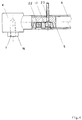
- a rectangular table top 1 is shown, the side edges of which the cross members 6 belong.
- the connection node 2 is shown, which comprises a head 4 and two arms 5.
- the crossbeams 6 are designed as precision steel tubes into which the arms 5 of the connecting node 2 can be inserted in a coherent manner.
- the arms On their underside, the arms have 5 recesses into which pressure pieces 17 are fitted.
- these pressure pieces 17 are clamped against the inner wall of the crossmember 6 by means of the setscrews 22, as a result of which the hold is established between the connecting node 2 and the crossmembers 6.
- 1 and 4 also show, in the case of a bore for a threaded pin 22 on the upper side of the cross member 6, a further bore for a chipboard screw 23, by means of which the cross member 6 is screwed onto the table top 1 via the spacer 19.
- the head 4 of the connecting node 2 has a bore 7 into which the stand column 3 can be screwed by means of the threaded pin 9.
- the pedestal 3 is expediently an extruded aluminum profile into which the threaded pin 9 is screwed.
- the head 4 also has a collar 16, over which a spacer 18 can be placed, which regulates the distance between the head 4 and the column 3.
- the tab 10 can also be used, preferably above its first hole 11, which is designed as an elongated hole.
- the tab 10 with the two holes 11 and 12 is shown in Fig. 2. As said, it is screwed with its slot 11 between the column 3 and the head 4 of a connecting node 2 on a table top 1 (Fig.1). The head 4 of the connecting node 2 of an adjacent table top 1 can then be hooked into its other hole 12 (FIG. 2). This is done by means of the plastic stopper 8.
- This is cup-shaped. It consists e.g. made of polypropylene. In its center it has a conical and ribbed pin 21.
- the plug 8 serves as a surface-protecting element when stacking the table tops 1.
- connection node 2 of the adjacent table top 1 is suspended in the tab 10 screwed between the connection node 2 and the pedestal 3 by means of the plastic plug 8 (not shown here).
- a stand column 3 is saved, which is not only advantageous in terms of material savings, but also increases the legroom of the users and aesthetically gives the table combination a lighter image.
- FIG. 5 a concatenation as shown in FIG. 5 is possible and advantageous:
- the concatenation takes place via the plastic clip 13, which is shown in a large view in FIG.
- That bracket consists for example of polypropylene. It has circularly curved grippers 14 and 15, the radius of which is somewhat below that of the tubular cross members 6, so that the clamp 13 can be clamped onto the cross member 6 in a tight fit.
- the clamp 13 is clamped with its gripper 14 onto the cross member 6 of a first table element. If an adjacent table element is then placed next to it for chaining, the clamp 13 can be pivoted by means of the handle 20 over the cross member 6 of this element.
Landscapes
- Engineering & Computer Science (AREA)
- General Engineering & Computer Science (AREA)
- Mechanical Engineering (AREA)
- Furniture Connections (AREA)
- Accommodation For Nursing Or Treatment Tables (AREA)
- Treatment Of Fiber Materials (AREA)
- Standing Axle, Rod, Or Tube Structures Coupled By Welding, Adhesion, Or Deposition (AREA)
- Mobile Radio Communication Systems (AREA)
Abstract
Description
- Die Erfindung betrifft ein System zum Erstellen variabler Tischkonfigurationen nach dem Oberbegriff des Anspruchs 1. Solche Systeme sind oftmals notwendig für Konferenzen, Festessen und dergleichen. Dabei soll das System nicht nur leicht aufzustellen sein, sondern seine Elemente sollen gleichzeitig auch leicht abzubauen, wegzuräumen und abzulagern sein.
- Eine solches System ist zum Beispiel aus einem Tischprogramm der Firma COR Helmut Lübke GmbH & Co unter der Bezeichnung "COR projekt" bekannt, bei welchem die kreiszylindrischen Tischbeine einen Lamellenkopf aufweisen, in dessen sich in Längsrichtung des Beines erstreckenden Lamellen Tischtraversen höhenverstellbar eingeklemmt werden können. Dieses Konzept ermöglicht zwar die Verkettung mit anderen Tischplatten, jedoch ist der Verkettungsvorgang relativ kompliziert und nicht ohne Werkzeug zu bewerkstelligen. Das bekannte Konzept stellt daher kein flexibles Verkettungssystem dar, dessen primäre Qualität in den handhabungsfreundlichen Auf- und Umbaumöglichkeiten liegt. Ferner erfordert die Herstellung des Lamellenkopfes einigen fabrikatorischen Aufwand. Des weiteren sind die Elemente dieses bekannten Systems nach Abbau nicht ohne Probleme abzulagern.
- DE-GM 94 16 016.3_beschreibt ein System zum Erstellen variabler Tisch-Konfigurationen, bei welchem Tische unter Bildung durchgehender Plattenflächen miteinander verkettbar sind. Die Tische als Elemente dieses Systems umfassen jeweils eine Tischplatte mit mindestens einer geradlinigen Seitenkante, je einem Verbindungsknoten in Form einer vertikal orientierten Hülse an den beiden Enden der Seitenkante, und Standsäulen, die mit den Verbindungsknoten fest verbindbar sind. Im Bereich der Hülsen sind umlaufende Ringnuten vorgesehen, in welche Ringplatten einsetzbar sind, die weitere Ringformen aufweisen, welche in die Ringnut der korrespondierenden Hülse der anzukettenden Tischplatte einsetzbar sind. Eine Verkettung der Tischplatten ist auch dadurch möglich, daß die unter der Platte verlaufenden Traversen einen dreieckförmigen oder trapezförmigen Querschnitt aufweisen, und mittels übergreifender, federnder, einschnappender Klammern miteinannder verbunden werden.
- Der wesentliche Nachteil dieses bekannten Systems besteht darin, daß seine Montage bzw. Demontage relativ kompliziert ist. Die Verbindung über die Klammern erfordert spezielle Profilquerschnitte und macht die Lagerhaltung und Fabrikation aufwendig.
- DE-GM 90 06 147.0_beschreibt ein Gestell mit Stangen aus Rundprofil und Eckverbindern, die die Form eines Würfels mit kreisförmigen Seitenflächen aufweisen. Auf diese Seitenflächen werden kreisrunde Rohre des gleichen Durchmessers dadurch aufgeschraubt, daß in ihnen Steckteile verspreizt werden, die ihrerseits mittels Schrauben an dem Würfel befestigt werden.
- Diese bekannte Technik taugt in der Praxis schon deshalb nicht zum Verketten von Tischplatten, weil die Verbindung der Rohre mit den Würfeln recht aufwendig ist.
- FR 2 402 430 beschreibt ein Gestell aus Rundrohren, dessen Eckverbindungen dreiarmige Steckhülsenelemente sind.
- Auch diese bekannten Systeme sind demnach wenig flexibel und handhabungsfreundlich soweit die Verkettung von Tischplatten betroffen ist.
- Es ist daher die Aufgabe der Erfindung, ein System zu konzipieren, welches einerseits die handhabungs- und umbaufreundliche Verkettung von Tischelementen ermöglicht, und dessen Elemente kostengünstig herzustellen sind, und das andererseits leicht abzubauen und abzulagern ist. Ferner muß es darüberhinaus natürlich im aufgebauten Zustand auch ästhetisch ansprechen.
- Diese Aufgabe wird durch die Merkmale des Anspruchs 1 und der Unteransprüche gelöst.
- Der Kern der Erfindung besteht darin, daß bei dem erfindungsgemäßen System als Elemente Tischplatten prinzipiell gleichen Aufbaus, jedoch in verschiedenen Formaten (z.B. 80er Raster, 70er Raster) und Formen (z.B. Rechteck, Quadrat, Trapez, Dreieck) vorgesehen sind, die in einfacher Weise miteinander verkettbar oder voneinander lösbar und durch Aufschrauben der Standsäulen bzw.
- Tischbeine zu Tischen komplettierbar sind, wobei diese Tischplatten bei abgeschraubten Beinen problemlos und kleinräumig lagerbar sind. Die System-Elemente sind robust und kostengünstig herzustellen, und das aufgebaute System ist sicher und stabil.
- Nachstehend wird die Erfindung anhand von in Zeichnungen dargestellten Ausführungsbeispielen näher erläutert. Dabei zeigt:
- Fig.1
- die perspektivische Ansicht in Explosions-Darstellung einer Tisch-Ecke mit zugehörigen Verbindungsknoten, Traversen und Standsäule,
- Fig.2
- eine Ansicht wie in Fig.1 jedoch ohne Standsäule und Details des Verbindungsknotens, aber mit Lasche und Plastikstopfen,
- Fig.3
- eine Ansicht wie in Fig. 1, wobei hier zwei Elemente über die Lasche verbunden sind,
- Fig.4
- eine Detailzeichnung des Verbindungsknotens,
- Fig.5a
- die Kunststoffklammer, und
- Fig.5
- die Kunststoffklammer eingesetzt zur Verbindung zweier Elemente.
- In Fig.1 ist eine rechteckige Tischplatte 1 dargestellt, zu deren Seitenkanten die Traversen 6 gehören. Ferner ist der Verbindungsknoten 2 dargestellt, der einen Kopf 4 und zwei Arme 5 umfaßt. Die Traversen 6 sind als Präzisions-Stahlrohre ausgebildet, in welche die Arme 5 des Verbindungsknotens 2 schlüssig eingeführt werden können. An ihrer Unterseite weisen die Arme 5 Ausnehmungen auf, in welche Druckstücke 17 eingepaßt sind. Wie näher in Fi.4 gezeigt werden diese Druckstücke 17 mittels der Gewindestifte 22 gegen die Innenwand der Traverse 6 gespannt, wodurch der Halt zwischen dem Verbindungsknoten 2 und den Traversen 6 hergestellt wird. Des weiteren zeigen Fig.1 und 4 bei einer Bohrung für einen Gewindestift 22 an der Oberseite der Traverse 6 zusätzlich eine weitere Bohrung für eine Spanplattenschraube 23, mittels welcher die Traverse 6 über das Distanzstück 19 an der Tischplatte 1 angeschraubt wird.
- Ferner ist aus Fig.1 und 4 ersichtlich, daß der Kopf 4 des Verbindungsknotens 2 eine Bohrung 7 aufweist, in welche die Standsäule 3 mittels des Gewindezapfens 9 eingeschraubt werden kann. Die Standsäule 3 ist zweckmäßigerweise ein Aluminium-Strangpreßprofil, in welches der Gewindezapfen 9 eingeschraubt ist. Weiter weist der Kopf 4 einen Bund 16 auf, über den eine Distanzscheibe 18 gelegt werden kann, die den Abstand zwischen Kopf 4 und Säule 3 regelt. Statt der Distanzscheibe 18 kann auch die Lasche 10 eingesetzt werden, vorzugsweise über ihr als Langloch ausgebildetes erstes Loch 11.
- Die Lasche 10 mit den beiden Löchern 11 und 12 ist in Fig. 2 dargestellt. Wie gesagt, wird sie mit ihrem Langloch 11 zwischen Standsäule 3 und Kopf 4 eines Verbindungsknotens 2 an einer Tischplatte 1 eingeschraubt (Fig.1). In ihr anderes Loch 12 kann dann der Kopf 4 des Verbindungsknotens 2 einer benachbarten Tischplatte 1 eingehängt werden (Fig.2). Dies erfolgt mittels des Plastikstopfens 8. Dieser ist topfförmig ausgebildet. Er besteht z.B. aus Polypropylen. In seiner Mitte weist er einen konischen und gerippten Zapfen 21 auf.
- Mit diesem Zapfen 21 wird er in die Bohrung 7 (Fig.4) des Kopfes 4 eingedrückt. Der innere Teil des Topfes umfaßt dann den Bund 16 des Kopfes 4. Der äußere Teil des Topfes weist einen Durchmesser auf, der etwas über dem Durchmesser des Loches 12 der Lasche 10 liegt, sodaß sich ein fester, schwergängiger Sitz des Stopfens 8 im Loch 12 ergibt. Im ausgehängten Zustand dient der Stopfen 8 als oberflächenschonendes Element beim Stapeln der Tischplatten 1.
- In Fig. 3 ist die beschriebene Verbindung im ausgeführten Zustand dargestellt: In die zwischen Verbindungsknoten 2 und Standsäule 3 eingeschraubte Lasche 10 ist der Verbindungsknoten 2 der benachbarten Tischplatte 1 mittels des (hier nicht gezeigten) Plastikstopfens 8 eingehängt.
- Wie ersichtlich wird bei der in Fig.3 gezeigten Konzeption eine Standsäule 3 eingespart, was nicht nur von der Materialersparnis her vorteilhaft ist, sondern auch die Beinfreiheit der Benutzer erhöht und der Tischkombination ästhetisch ein leichteres Bild gibt.
- Wo es jedoch - aus welchen Gründen auch immer - nicht möglich oder erwünscht ist, von der in Fig.3 gezeigten vorteilhaften Verkettung Gebrauch zu machen, ist eine Verkettung wie in Fig.5 gezeigt möglich und vorteilhaft:
Hier erfolgt die Verkettung über die Kunststoffklammer 13, die in Großansicht in Fig.5a dargestellt ist. Diese Klammer besteht z.B. aus Polypropylen. Sie weist kreisförmig gebogene Greifer 14 und 15 auf, deren Radius etwas unter dem der rohrförmigen Traversen 6 liegt, sodaß sich die Klammer 13 in festem Sitz auf die Traverse 6 klemmen läßt. Die Klammer 13 wird mit ihrem Greifer 14 auf die Traverse 6 eines ersten Tisch-Elementes geklemmt. Wenn dann ein benachbartes Tisch-Element zur Verkettung daneben gestellt wird, kann die Klammer 13 mittels des Griffes 20 über die Traverse 6 dieses Elementes geschwenkt werden. - Statt der in Fig.2 und 3 gezeigten Verkettung über den in das Loch 12 der Lasche 10 eingreifenden Plastistopfen 8 ist es auch möglich, den Stopfen 8 zu entfernen, das Loch 12 über den Bund 16 des Kopfes 4 zu ziehen, und die Lasche dann über eine nicht gezeigte Rändelschraube am Kopf 4 zu befestigen.
- Mit dem erfindungsgemäßen System wird es möglich, aus kleinräumig lagerbaren Tischplatten gleichen Aufbaus jedoch verschiedener Formate und Formen in einfacher Weise stabile und ästhetisch ansprechende Tischkonfigurationen unterschiedlichster Art herzustellen, wobei der Herstellungsaufwand der System-Elemente bescheiden und damit sehr kostengünstig ist.
-
- 1
- Tischplatte
- 2
- Verbindungsknoten
- 3
- Standsäule
- 4
- Kopf
- 5
- Arm
- 6
- Traverse
- 7
- Bohrung (im Kopf)
- 8
- Plastikstopfen
- 9
- Gewindezapfen (an Standsäule)
- 10
- Lasche
- 11
- erstes Loch (Langloch)
- 12
- zweites Loch (Kreisloch)
- 13
- Kunststoff-Klammer
- 14
- erster Greifer
- 15
- zweiter Greifer
- 16
- Bund
- 17
- Druckstück
- 18
- Distanzscheibe
- 19
- Distanzstück
- 20
- Griff
- 21
- Zapfen
- 22
- Gewindestift
- 23
- Spanplattenschraube
Claims (9)
- System zum Erstellen variabler Tisch-Konfigurationen, bei welchem Tische unter Bildung durchgehender Plattenflächen miteinander verkettbar sind, wobei ein Element dieses Systems mindestens die folgenden Teile umfaßt:- eine Tischplatte (1) mit mindestens einer geradlinigen Seitenkante,- je einen Verbindungsknoten (2) an beiden Enden der Seitenkanten,- drei Standsäulen (3), die mit den Verbindungsknoten (2) fest verbindbar sind,dadurch gekennzeichnet, daß- ein Verbindungsknoten (2) aus einem Kopf (4) mit zwei Armen (5) besteht, und- die beiden Arme (5) sich in unterschiedlicher Richtung parallel zur Tischplatte (1) erstrecken und zur Verbindung mit je einer Traverse (6) ausgebildet sind, welche unter der Tischplatte (1) befestigbar sind, und- der Kopf (4) senkrecht zur Tischplatte (1) eine Bohrung (7) aufweist, in welcher formschlüssig eine Standsäule (3), ein Plastikstopfen (8) oder eine Rändelschraube befestigbar sind.
- System nach Anspruch 1, dadurch gekennzeichnet, daß- die Bohrung (7) im Kopf (4) des Verbindungsknotens (2) ein Gewinde aufweist, in welches die Standsäule (3) mittels eines Gewindezapfens (9) einschraubbar ist, und- eine Lasche (10) mit zwei Löchern (11,12) vorgesehen ist, die über ihr eines Loch (11) mittels der Standsäule (3) an dem Kopf (4) des Verbindungsknotens (2) anschraubbar ist, und in deren anderem Loch (12) der Kopf (4) eines Verbindungsknotens (2) einer benachbarten Tischplatte (1) befestigbar ist.
- System nach Anspruch 1 oder 2, dadurch gekennzeichnet, daß des weiteren eine elastische Kuststoff-Klammer (13) vorgesehen ist, die- mittels eines ersten Greifers (14) schwenkbar auf die Traverse (6) eines ersten Tisch-Elementes aufsetzbar ist, und- mittels eines zweiten Greifers (15) auf die Traverse (6) eines zweiten, dem ersten Element benachbarten Tisch-Elementes aufklammerbar ist.
- System nach Anspruch 2, dadurch gekennzeichnet,- daß der Kopf (4) des Verbindungsknotens (2) auf der Seite der Bohrung (7) einen zylindrischen Bund (16) aufweist, dessen Durchmesser dem des zweiten Loches (12) der Lasche (10) entspricht,- daß die an den Armen (5) des Verbindungsknotens (2) befestigbaren Traversen (6) rohrförmig ausgebildet sind,- daß die Arme (5) des Verbindungsknotens (2) zusammmen mit einem Druckstück (17) in die Traversen (6) einführbar sind, und die Druckstücke (17) mittels Gewindestiften (18) in der Traverse (6) verspannbar sind, und- daß Distanzstücke (19) vorgesehen sind, über welche die Traversen (6) an der Tischplatte (1) befestigbar sind.
- System nach Ansprüchen 3 und 4, dadurch gekennzeichnet, daß die beiden Greifer (14,15) der Kunststoff-Klammer (13) jeweils aus zwei Fingern bestehen, die die Traversen (6) auf den beiden Seiten eines Distanzstückes (19) umgreifen, und die Kunststoff-Klammer (13) einen Griff (20) zum manuellen Schwenken aufweist.
- System nach Anspruch 4, dadurch gekennzeichnet, daß der Plastikstopfen (8) topfförmig mit einem zentrischen Zapfen (21) ausgebildet ist, und- der Innendurchmesser des Topfes derart ist, daß er den Bund (16) am Kopf (4) des Verbindungsknotens (2) umfaßt, und- der Außendurchmesser des Topfes derart ist, daß er schwergängig in das Loch (12) einer Lasche (10) eindrückbar ist, und- der Zapfen (21) konisch ausgebildet und gerippt ist derart, daß er durch Eindrücken in der Bohrung (7) des Kopfes (4) des Verbindungsknotens (2) befestigbar ist.
- System nach einem der vorhergehenden Ansprüche, dadurch gekennzeichnet, daß alle Tischplatten (1) im Aufbau gleich sind, jedoch unterschiedliche Raster-Formate und geometrische Formen aufweisen.
- System nach einem der vorhergehenden Ansprüche, dadurch gekennzeichnet, daß die Verbindungsknoten (2) Aluminium-Gußteile sind, und die Standsäulen (3) Aluminium-Strangpreßprofile.
- System nach Anspruch 4, dadurch gekennzeichnet, daß die Lasche (10) in dem Loch (12), das nicht über die Standsäule (3) an dem ersten Verbindungsknoten (2) angeschraubt ist, an dem zweiten Verbindungsknoten (2) mittels einer Rändelschraube befestigbar ist.
Applications Claiming Priority (2)
| Application Number | Priority Date | Filing Date | Title |
|---|---|---|---|
| DE19530780A DE19530780A1 (de) | 1995-08-22 | 1995-08-22 | System zum Erstellen variabler Tischkonfigurationen |
| DE19530780 | 1995-08-22 |
Publications (3)
| Publication Number | Publication Date |
|---|---|
| EP0761129A2 true EP0761129A2 (de) | 1997-03-12 |
| EP0761129A3 EP0761129A3 (de) | 2001-01-17 |
| EP0761129B1 EP0761129B1 (de) | 2003-01-08 |
Family
ID=7770049
Family Applications (1)
| Application Number | Title | Priority Date | Filing Date |
|---|---|---|---|
| EP96112639A Expired - Lifetime EP0761129B1 (de) | 1995-08-22 | 1996-08-05 | System zum Erstellen variabler Tischkonfigurationen |
Country Status (4)
| Country | Link |
|---|---|
| EP (1) | EP0761129B1 (de) |
| AT (1) | ATE230575T1 (de) |
| DE (2) | DE19530780A1 (de) |
| ES (1) | ES2187596T3 (de) |
Cited By (4)
| Publication number | Priority date | Publication date | Assignee | Title |
|---|---|---|---|---|
| WO2001086156A1 (en) * | 2000-05-09 | 2001-11-15 | Soederlund Stefan | Assembling means |
| EP1260157A3 (de) * | 2001-05-17 | 2003-07-16 | Work Corporation Inc. S.r.l. | Gebilde bestehend aus Möbelteilen mit veränderlicher Zusammensetzung |
| FR2870443A1 (fr) * | 2004-05-21 | 2005-11-25 | Atal Sa | Mobiliers de bureau, et plus particulierement des mobiliers de bureau demontables |
| DE102016206748A1 (de) * | 2016-04-21 | 2017-10-26 | Habermaass Gmbh | Möbelstück mit einem Eckverbinder |
Families Citing this family (4)
| Publication number | Priority date | Publication date | Assignee | Title |
|---|---|---|---|---|
| ES2311377B1 (es) * | 2006-10-25 | 2009-12-02 | Akaba, S.A. | Armazon-bastidor para mesas de configuracion variable. |
| GR1006721B (el) * | 2008-12-19 | 2010-03-09 | Αθανασιος Κωνσταντινου Παπαπαναγιωτου | Συνδεσμολογια μεταλλικων σωληνωτων στοιχειων με κομβο εσωτερικης συνδεσης |
| TWM486995U (zh) * | 2014-04-03 | 2014-10-01 | Timotion Technology Co Ltd | 易於展收的電動桌腳架 |
| CN219515593U (zh) * | 2023-01-18 | 2023-08-15 | 浙江永强集团股份有限公司 | 一种拆装式户外桌 |
Family Cites Families (7)
| Publication number | Priority date | Publication date | Assignee | Title |
|---|---|---|---|---|
| FR2135510B1 (de) * | 1971-05-06 | 1973-05-11 | Garde Paul | |
| DE2155234A1 (de) * | 1971-11-06 | 1973-05-10 | Rolf Voelkle | Nach dem baukastenprinzip zusammensetzbares gestell |
| FR2402430A1 (fr) * | 1977-09-12 | 1979-04-06 | Alsace Sa Plastra Plastiques | Petit meuble du type table, presentant un ou plusieurs elements de support suspendus |
| GB8326429D0 (en) * | 1983-10-03 | 1983-11-02 | Chiu Ping | Joint structure |
| US5035186A (en) * | 1988-03-05 | 1991-07-30 | Roder Gmbh Sitzmobelwerke | Table having a connection device |
| DE9006147U1 (de) * | 1990-05-31 | 1991-09-26 | Gerd und Bernd Vieler KG, 5860 Iserlohn | Display-Gestell aus Rundprofil-Stangen und Eckverbindern zur Präsentation und zum Verkauf von Waren |
| DE9416016U1 (de) * | 1994-10-05 | 1995-01-05 | Ensslen GmbH, 72222 Ebhausen | Tisch |
-
1995
- 1995-08-22 DE DE19530780A patent/DE19530780A1/de not_active Withdrawn
-
1996
- 1996-08-05 DE DE59610038T patent/DE59610038D1/de not_active Expired - Fee Related
- 1996-08-05 EP EP96112639A patent/EP0761129B1/de not_active Expired - Lifetime
- 1996-08-05 AT AT96112639T patent/ATE230575T1/de not_active IP Right Cessation
- 1996-08-05 ES ES96112639T patent/ES2187596T3/es not_active Expired - Lifetime
Cited By (5)
| Publication number | Priority date | Publication date | Assignee | Title |
|---|---|---|---|---|
| WO2001086156A1 (en) * | 2000-05-09 | 2001-11-15 | Soederlund Stefan | Assembling means |
| EP1260157A3 (de) * | 2001-05-17 | 2003-07-16 | Work Corporation Inc. S.r.l. | Gebilde bestehend aus Möbelteilen mit veränderlicher Zusammensetzung |
| US6805060B2 (en) | 2001-05-17 | 2004-10-19 | Work Corporation, Inc. S.R.L. | Structure for pieces of furniture with variable configuration |
| FR2870443A1 (fr) * | 2004-05-21 | 2005-11-25 | Atal Sa | Mobiliers de bureau, et plus particulierement des mobiliers de bureau demontables |
| DE102016206748A1 (de) * | 2016-04-21 | 2017-10-26 | Habermaass Gmbh | Möbelstück mit einem Eckverbinder |
Also Published As
| Publication number | Publication date |
|---|---|
| DE59610038D1 (de) | 2003-02-13 |
| ES2187596T3 (es) | 2003-06-16 |
| EP0761129B1 (de) | 2003-01-08 |
| DE19530780A1 (de) | 1997-02-27 |
| ATE230575T1 (de) | 2003-01-15 |
| EP0761129A3 (de) | 2001-01-17 |
Similar Documents
| Publication | Publication Date | Title |
|---|---|---|
| DE3049957C2 (de) | Geraetegestell | |
| DE2934795C3 (de) | Anordnung zur lösbaren Verbindung von Bauteilen | |
| EP0761129A2 (de) | System zum Erstellen variabler Tischkonfigurationen | |
| EP4064939B1 (de) | Rohrverbindungsstruktur und möbelbausatz | |
| DE202021105006U1 (de) | Anpassungsvorrichtung für Weihnachtsbaumfuß | |
| DE3537977C2 (de) | ||
| DE102004002394A1 (de) | Set zum Zusammensetzen von Möbeln, entsprechendes Möbel und Verfahren zum Aufbau eines Möbels bzw. zum Bereitstellen eines Sets | |
| DE2518896C3 (de) | ||
| DE3920959C2 (de) | ||
| DE29521508U1 (de) | System zum Erstellen variabler Tischkonfigurationen | |
| DE19522037A1 (de) | Vorrichtung zum Verbinden einer Möbel-Standsäule mit einem Trägerteil | |
| DE10030919A1 (de) | Zerlegbarer Profilrahmen sowie Tischsystem mit einem solchen Profilrohrrahmen | |
| DE19526932C1 (de) | Tisch | |
| DE2142470A1 (de) | Tisch | |
| DE3611445C2 (de) | ||
| DE8336732U1 (de) | Verbindungselement für Baukasten-Möbel | |
| DE4219852A1 (de) | Vorrichtung für ein schraubenlos zusammenfügbares Regalsystem | |
| EP0405157A2 (de) | Höhenverstellbares Standbein für Möbelstücke od. dgl. | |
| DE4428390A1 (de) | Tischuntergestellsystem zur Aufnahme und zum Befestigen einer Tischplatte | |
| DE7910865U1 (de) | Regal | |
| DE3715932C1 (en) | Table combination | |
| DE29613928U1 (de) | Zerlegbares Standbein | |
| DE8330969U1 (de) | Gerüst | |
| DE8810286U1 (de) | Vielseitig verwendbare Regaleinrichtung | |
| CH718420B1 (de) | Essgeschirrhalter |
Legal Events
| Date | Code | Title | Description |
|---|---|---|---|
| PUAI | Public reference made under article 153(3) epc to a published international application that has entered the european phase |
Free format text: ORIGINAL CODE: 0009012 |
|
| AK | Designated contracting states |
Kind code of ref document: A2 Designated state(s): AT CH DE ES FR GB IT LI NL |
|
| PUAL | Search report despatched |
Free format text: ORIGINAL CODE: 0009013 |
|
| AK | Designated contracting states |
Kind code of ref document: A3 Designated state(s): AT CH DE ES FR GB IT LI NL |
|
| RIC1 | Information provided on ipc code assigned before grant |
Free format text: 7A 47B 87/00 A, 7A 47B 13/02 B, 7F 16B 12/40 B, 7A 47B 13/06 B |
|
| 17P | Request for examination filed |
Effective date: 20010522 |
|
| 17Q | First examination report despatched |
Effective date: 20020213 |
|
| GRAG | Despatch of communication of intention to grant |
Free format text: ORIGINAL CODE: EPIDOS AGRA |
|
| GRAG | Despatch of communication of intention to grant |
Free format text: ORIGINAL CODE: EPIDOS AGRA |
|
| GRAG | Despatch of communication of intention to grant |
Free format text: ORIGINAL CODE: EPIDOS AGRA |
|
| GRAH | Despatch of communication of intention to grant a patent |
Free format text: ORIGINAL CODE: EPIDOS IGRA |
|
| GRAH | Despatch of communication of intention to grant a patent |
Free format text: ORIGINAL CODE: EPIDOS IGRA |
|
| GRAA | (expected) grant |
Free format text: ORIGINAL CODE: 0009210 |
|
| AK | Designated contracting states |
Kind code of ref document: B1 Designated state(s): AT CH DE ES FR GB IT LI NL |
|
| REF | Corresponds to: |
Ref document number: 230575 Country of ref document: AT Date of ref document: 20030115 Kind code of ref document: T |
|
| REG | Reference to a national code |
Ref country code: GB Ref legal event code: FG4D Free format text: NOT ENGLISH |
|
| REG | Reference to a national code |
Ref country code: CH Ref legal event code: EP |
|
| REF | Corresponds to: |
Ref document number: 59610038 Country of ref document: DE Date of ref document: 20030213 Kind code of ref document: P |
|
| GBT | Gb: translation of ep patent filed (gb section 77(6)(a)/1977) |
Effective date: 20030401 |
|
| ET | Fr: translation filed | ||
| REG | Reference to a national code |
Ref country code: ES Ref legal event code: FG2A Ref document number: 2187596 Country of ref document: ES Kind code of ref document: T3 |
|
| PGFP | Annual fee paid to national office [announced via postgrant information from national office to epo] |
Ref country code: NL Payment date: 20030728 Year of fee payment: 8 Ref country code: GB Payment date: 20030728 Year of fee payment: 8 Ref country code: CH Payment date: 20030728 Year of fee payment: 8 |
|
| PGFP | Annual fee paid to national office [announced via postgrant information from national office to epo] |
Ref country code: AT Payment date: 20030729 Year of fee payment: 8 |
|
| PGFP | Annual fee paid to national office [announced via postgrant information from national office to epo] |
Ref country code: DE Payment date: 20030805 Year of fee payment: 8 |
|
| PGFP | Annual fee paid to national office [announced via postgrant information from national office to epo] |
Ref country code: ES Payment date: 20030808 Year of fee payment: 8 |
|
| PGFP | Annual fee paid to national office [announced via postgrant information from national office to epo] |
Ref country code: FR Payment date: 20030813 Year of fee payment: 8 |
|
| PLBE | No opposition filed within time limit |
Free format text: ORIGINAL CODE: 0009261 |
|
| STAA | Information on the status of an ep patent application or granted ep patent |
Free format text: STATUS: NO OPPOSITION FILED WITHIN TIME LIMIT |
|
| 26N | No opposition filed |
Effective date: 20031009 |
|
| PG25 | Lapsed in a contracting state [announced via postgrant information from national office to epo] |
Ref country code: GB Free format text: LAPSE BECAUSE OF NON-PAYMENT OF DUE FEES Effective date: 20040805 Ref country code: AT Free format text: LAPSE BECAUSE OF NON-PAYMENT OF DUE FEES Effective date: 20040805 |
|
| PG25 | Lapsed in a contracting state [announced via postgrant information from national office to epo] |
Ref country code: ES Free format text: LAPSE BECAUSE OF NON-PAYMENT OF DUE FEES Effective date: 20040806 |
|
| PG25 | Lapsed in a contracting state [announced via postgrant information from national office to epo] |
Ref country code: LI Free format text: LAPSE BECAUSE OF NON-PAYMENT OF DUE FEES Effective date: 20040831 Ref country code: CH Free format text: LAPSE BECAUSE OF NON-PAYMENT OF DUE FEES Effective date: 20040831 |
|
| PG25 | Lapsed in a contracting state [announced via postgrant information from national office to epo] |
Ref country code: NL Free format text: LAPSE BECAUSE OF NON-PAYMENT OF DUE FEES Effective date: 20050301 Ref country code: DE Free format text: LAPSE BECAUSE OF NON-PAYMENT OF DUE FEES Effective date: 20050301 |
|
| GBPC | Gb: european patent ceased through non-payment of renewal fee |
Effective date: 20040805 |
|
| REG | Reference to a national code |
Ref country code: CH Ref legal event code: PL |
|
| PG25 | Lapsed in a contracting state [announced via postgrant information from national office to epo] |
Ref country code: FR Free format text: LAPSE BECAUSE OF NON-PAYMENT OF DUE FEES Effective date: 20050429 |
|
| NLV4 | Nl: lapsed or anulled due to non-payment of the annual fee |
Effective date: 20050301 |
|
| REG | Reference to a national code |
Ref country code: FR Ref legal event code: ST |
|
| PG25 | Lapsed in a contracting state [announced via postgrant information from national office to epo] |
Ref country code: IT Free format text: LAPSE BECAUSE OF NON-PAYMENT OF DUE FEES;WARNING: LAPSES OF ITALIAN PATENTS WITH EFFECTIVE DATE BEFORE 2007 MAY HAVE OCCURRED AT ANY TIME BEFORE 2007. THE CORRECT EFFECTIVE DATE MAY BE DIFFERENT FROM THE ONE RECORDED. Effective date: 20050805 |
|
| REG | Reference to a national code |
Ref country code: ES Ref legal event code: FD2A Effective date: 20040806 |