EP0758034B1 - Dispositif et procédé pour raccorder deux éléments en béton précontraint - Google Patents
Dispositif et procédé pour raccorder deux éléments en béton précontraint Download PDFInfo
- Publication number
- EP0758034B1 EP0758034B1 EP96109873A EP96109873A EP0758034B1 EP 0758034 B1 EP0758034 B1 EP 0758034B1 EP 96109873 A EP96109873 A EP 96109873A EP 96109873 A EP96109873 A EP 96109873A EP 0758034 B1 EP0758034 B1 EP 0758034B1
- Authority
- EP
- European Patent Office
- Prior art keywords
- prestressed concrete
- joining
- prestressed
- cords
- concrete element
- Prior art date
- Legal status (The legal status is an assumption and is not a legal conclusion. Google has not performed a legal analysis and makes no representation as to the accuracy of the status listed.)
- Expired - Lifetime
Links
Images


Classifications
-
- E—FIXED CONSTRUCTIONS
- E01—CONSTRUCTION OF ROADS, RAILWAYS, OR BRIDGES
- E01D—CONSTRUCTION OF BRIDGES, ELEVATED ROADWAYS OR VIADUCTS; ASSEMBLY OF BRIDGES
- E01D21/00—Methods or apparatus specially adapted for erecting or assembling bridges
-
- E—FIXED CONSTRUCTIONS
- E01—CONSTRUCTION OF ROADS, RAILWAYS, OR BRIDGES
- E01D—CONSTRUCTION OF BRIDGES, ELEVATED ROADWAYS OR VIADUCTS; ASSEMBLY OF BRIDGES
- E01D2/00—Bridges characterised by the cross-section of their bearing spanning structure
-
- E—FIXED CONSTRUCTIONS
- E04—BUILDING
- E04H—BUILDINGS OR LIKE STRUCTURES FOR PARTICULAR PURPOSES; SWIMMING OR SPLASH BATHS OR POOLS; MASTS; FENCING; TENTS OR CANOPIES, IN GENERAL
- E04H12/00—Towers; Masts or poles; Chimney stacks; Water-towers; Methods of erecting such structures
- E04H12/16—Prestressed structures
-
- E—FIXED CONSTRUCTIONS
- E01—CONSTRUCTION OF ROADS, RAILWAYS, OR BRIDGES
- E01D—CONSTRUCTION OF BRIDGES, ELEVATED ROADWAYS OR VIADUCTS; ASSEMBLY OF BRIDGES
- E01D2101/00—Material constitution of bridges
- E01D2101/20—Concrete, stone or stone-like material
- E01D2101/24—Concrete
- E01D2101/26—Concrete reinforced
- E01D2101/28—Concrete reinforced prestressed
Definitions
- the invention relates to a device for connecting Prestressed concrete elements according to the preamble of claim 1 and a method for connecting prestressed concrete elements according to the preamble of claim 17.
- prestressed concrete elements such as masts, towers or for example bridges
- structures made of prestressed concrete elements are built by individual Prestressed concrete elements can be connected on site.
- prestressed concrete elements There a production of prestressed concrete elements a considerable equipment costs, these are not on site at the Construction site, but in special manufacturing facilities manufactured.
- the subsequent transport of the prefabricated Prestressed concrete elements to the construction site forces to predetermined ones Maximum dimensions for the dimensions of the prestressed concrete elements are not too exceed. Therefore, the individual prestressed concrete elements be assembled on site.
- FIG. 4 shows the joint area of two prestressed concrete pipes 110 and 120 in a half-sectional view.
- the prestressed concrete pipes are arranged in a circular symmetry around the axis 112.
- Both Prestressed concrete pipes are crisscrossed with tendons 114, which end in the area of a thrust plate 130.
- the cleat 130 are made of metal and have conical holes, in which the tension wire strands 114 with a wedge anchor 116 be attached. Rods are attached to the push plates 130 118 attached, especially butt welded to the plate.
- the two thrust plates 130 two with the end faces adjacent prestressed concrete pipes 110, 120 are by means of Centering pin 122 aligned and then the two Bolt plates screwed or welded together.
- a suitable one Sealing sealing material such as synthetic resin.
- the joints between the individual prestressed concrete components are, for example, with towers and masts that using such elements, by visible from far away and interrupted by the thick, protruding cleats the otherwise slim Lines.
- the solution according to the invention leads to a direct one Continue the ones running in a first prestressed concrete element Tension wire strands, hereinafter referred to as short first strands, in a second prestressed concrete element into it, which with the first Prestressed concrete element forms a joint.
- first strands emerging from a first prestressed concrete element into the second prestressed concrete element the power flow always within the two adjacent Prestressed concrete elements guided. This allows one achieve an even flow of force.
- the advantageous for connecting prestressed concrete elements is characterized in that the first strands emerging from the first prestressed concrete element be inserted into openings in the second prestressed concrete element, the two prestressed concrete elements to be connected side by side be arranged and the first strands in the second Prestressed concrete element can be braced.
- the first occur Strands in tubular cavities in the second prestressed concrete element which are formed by cladding tubes.
- the first strands simply are inserted into the second prestressed concrete elements.
- the cladding tubes have the advantage that after a another advantageous embodiment of the invention, this with a filler can be filled.
- the filler can be a lubricant, but also after one another advantageous embodiment, a curing Material such as cement or milk of lime.
- a filler material in the form of a hardening material can after injecting this hardening material in the tubular cavities and after the material has hardened, the preload of the first Strands added and in the second prestressed concrete element be transmitted.
- the first Strands after entering the second prestressed concrete element curved path.
- the provision of a curved The course of the path is advantageous because the first strands end near a wall of the second prestressed concrete element and from there can be braced from the outside. This is required because a suitable clamping device, for example in the form of a hydraulic press, from the outside must be applied and operated.
- the inventive device for connecting Prestressed concrete elements can advantageously be used to connect Prestressed concrete pipes, especially centrifugal concrete pipes, are used become.
- it can be connected Prestressed concrete pipes, which from a first prestressed concrete pipe into one second prestressed concrete pipe entering the first strands completely run inside the wall of the second prestressed concrete pipe or along its course partially outside the wall of the second prestressed concrete pipe.
- the longitudinal their course partially outside the wall of the second Prestressed concrete pipe led first strands in the case of Connecting prestressed concrete pipes through the outer surface, but also through the inner surface of the second Prestressed concrete pipe, step through.
- first strands can be fixed under tension in one End anchorage.
- Such anchoring can for example in a wedge anchoring area, the first Pick up strands and already in the second prestressed concrete element be firmly installed during transport to the installation site.
- first strands and one fixed position of the end anchorages is also an even, preselected preload in the associated end anchors fixed first strands reached.
- connections between the first strands and the associated end anchors releasable and the End anchor after filling material into the tubular cavities from the second prestressed concrete element removable.
- the end anchorings can then be removed possible if the filling material has the pre-tensioning force of the first Strands transferred to the second prestressed concrete element.
- a Removing the end anchors makes sense if the End anchors to be reused and the Removal of the end anchors causes lower costs than the use of new end anchors.
- the device is the end anchorage near a wall of the Prestressed concrete element attached and by a Prestressed concrete element molded-in prestressing chamber accessible. This allows the first to be braced in a convenient manner Stranded, but also a possible removal of the End anchors after curing an injected Filling material can be made.
- Coil spring near the end anchorage around the first strands arranged. Because of the advantageously curved The course of the first strands is created in the prestressed concrete element Force components in two different directions, with radial use of prestressed concrete pipes Force component is present. This force component, the not along those cast in the prestressed concrete element Tension wire strands runs through the coil spring dampened the explosive effect of this force component reduced.
- the advantageous method of connecting Prestressed concrete elements is characterized by the characteristic features of Claim 17 characterized.
- the clamping chambers according to the Inject the filler This will make the ending in the tensioning elements, or after removal of the Clamping elements with free ends of the first strands against environmental influences protected. They may also be at one Prestressed concrete element removed from the outside of the prestressing chambers and achieved a smooth outer surface of the prestressed concrete element.
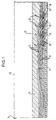
- FIG. 1 shows a cladding tube guide according to the invention.
- the second prestressed concrete pipe which is generally with Reference number 12 is designated.
- the second prestressed concrete pipe 12 is on the end face 14 with a not shown connected the first prestressed concrete pipe.
- the prestressed concrete pipe 12 is around the axis 16 is rotationally symmetrical.
- the tension strands 22 are preferably as is shown in Fig., arranged in the network and are in following to their belonging to the second Highlight concrete pipe 12, referred to as second strands.
- the second strands preferably run parallel to one another in the axial direction within the wall 18 of the second Prestressed concrete pipe 12.
- second strands 22 Due to the embedding in the concrete wall 18 second strands 22 not in special end anchorages fixed, but run up to the front joint 14 or until shortly before the end face 14 and end there. Consequently is the entire second prestressed concrete pipe 12 before it is installed in a biased condition.
- the second Strands also in suitable anchors, for example in Form of wedge anchors, ends, or until just before the front end 14 guided second strands through the Apply a sealing material before Weather influences are protected.
- Another, third is to be attached to the second prestressed concrete pipe Prestressed concrete pipe (not shown) are connected, see above the second strands protrude from one face of the second prestressed concrete pipe facing the second Prestressed concrete pipe 12.
- Prestressed concrete pipe (not shown) are connected, see above the second strands protrude from one face of the second prestressed concrete pipe facing the second Prestressed concrete pipe 12.
- Cladding tubes 24 are formed in the second prestressed concrete tube the inclusion of the first not shown Prestressed concrete element emerging, serve first strands.
- the cladding tubes 24 can be used in the manufacture of the second Prestressed concrete pipe individually in the second prestressed concrete pipe molded, but can also be part of a prefabricated mounting insert 26, which is both the Cladding tubes 24, as well as reinforcing coils 28, on rings welded radial rods 30 and end anchors 32 with Includes springs 34.
- a prefabricated mounting insert 26 which is both the Cladding tubes 24, as well as reinforcing coils 28, on rings welded radial rods 30 and end anchors 32 with Includes springs 34.
- the first emerging from the first prestressed concrete element Strands run inside the cladding tubes 24 and end in End anchors 32, the wall of the Prestressed concrete element each through a prestressing chamber 38 are accessible.
- the end anchors 32 can be on different ways are carried out, for example in the form of wedge anchors, but also in the form of Screw connections by connecting the first strands with a Threaded bolts are connected on which a nut can be screwed on.
- the cladding tubes 24 preferably have a structured one Shell surface, for example in corrugated or corrugated Shape. This has the advantage that after injecting a hardening material in the cladding tubes 24 this hardens and a firm connection between the one in question Cladding tube guided first strand and the cladding tube. Due to the structured surface of the cladding tube, the in tractive force without axial direction of the first strand Risk of slippage between the cladding tube and the surrounding concrete material of the second prestressed concrete pipe in the transfer the second prestressed concrete pipe.
- the springs 34 and radial rods 30 each serve the strength of the second prestressed concrete pipe 12 in the area of End anchorages 32 to increase, as well as due to the in Fig. 1 shown curved path of the cladding Force components occurring perpendicular to the longitudinal axis of the Take prestressed concrete pipe 12.
- a curved course of the cladding tubes 24 in the second Prestressed concrete pipe 12 stems from the fact that the end anchors 32 of must be accessible from a wall of the prestressed concrete pipe. Because of the method for connecting two prestressed concrete elements must be in the second Prestressed concrete element inserted first strands are braced which is why the ends of the first strands are accessible from the outside have to.
- the course of the cladding tubes shown in Fig. 1 is pure exemplary, but represents a course in which none small bending radii occur.
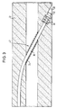
- Fig. 2 shows an embodiment in which a first Strand 36 partially outside of the second tensioning element 12 to be led.
- This embodiment is used in particular when if prestressed concrete elements with a small thickness with each other to be connected, for example, prestressed concrete pipes with a small wall thickness.
- the Routing of the first strands partially outside the concrete wall of the second prestressed concrete element because there is not enough space is located within the wall of the second prestressed concrete pipe, to next to the second strands (not shown) and the further reinforcement elements in the form of the reinforcement helix 28, the springs 34 or also with reference to FIG. 1 illustrated radial rods additionally the cladding tubes 24 to run completely within the concrete wall.
- Another Reason for the partially outside of the second Prestressed concrete element guided cladding lies in that on this way very large radii of curvature of the first strands are achievable.
- a suitable cladding tube 24 into which a suitable filling material, such as a lubricant or a hardening material, e.g. cement or lime milk, is injected.
- a suitable filling material such as a lubricant or a hardening material, e.g. cement or lime milk
- the cladding tube is preferably a steel tube and can during its course outside the wall of the second Prestressed concrete element by an additional support ring 40 be fixed in position.
- Fig. 3 shows an embodiment in which the within a second prestressed concrete pipe through the first strand Inner jacket of the second prestressed concrete pipe is passed. In the embodiment shown in Fig. 3 occur first strands at diametrically arranged locations the inner wall of the prestressed concrete pipe and on again.
- This embodiment is also preferably used if prestressed concrete elements, especially prestressed concrete pipes, are low Diameter, are interconnected.
- the two prestressed concrete elements to be connected are in short distance from each other, with those to be brought into contact Butt surfaces, arranged facing each other.
- the from the first prestressed concrete element with a predetermined The first strands emerging from the protrusion are inserted into the respective outlet openings from the first prestressed concrete element corresponding entry openings in the second Prestressed concrete element introduced and by the in the second Prestressed concrete elements provided cavities, especially in the form from cladding tubes until exit from the second Prestressed concrete element introduced.
- the first strands are each from the second Prestressed concrete element emerged, so the two become connecting prestressed concrete elements in contact with the butt sides brought together and the first strands under tension fixed the second prestressed concrete element.
- the creation of the Tension can be reduced, for example, by using hydraulic presses happen, each one defined Can apply tension to the individual first strands.
- each one defined Can apply tension to the individual first strands.
- the two prestressed concrete elements to be connected pressed firmly against each other and fixed in this position.
- In front tensioning the first strands can lead to the butt sides of the connecting prestressed concrete elements with a suitable sealing coating to be provided to prevent penetration of moisture in the joint joint to prevent connected prestressed concrete elements.
- the then fixing the first strands in the second Prestressed concrete element is made using suitable end anchorages performed as they are known in the art.
- a filling material is injected into the cladding tubes, either just avoid corrosion on the first strands should or additional forces on the prestressed concrete element to transmit.
- a is preferred Lubricants such as grease are applied, in the second case it offers itself Cement, or a similar building material. Alternatively, you can a curing resin mixture can also be injected.
- a filler is used with which the Tension forces in the first strand in the form of Compressive forces on the surrounding concrete material of the second Prestressed concrete element can be transferred End anchorage to be carried out weaker or after Curing of the filling material can be removed again. This is possible because the end anchorage is only in the Installation state must absorb forces after the curing of the Filling material, however, the forces directly from the first strands over the hardened filling material and the cladding tubes into the second prestressed concrete element are transferred.
- the filling material is injected from the impact surface between the first and second prestressed concrete element.
- the Filling material is preferably arranged radially Injected into the second prestressed concrete element and fills the cavities in the cladding tubes until the fill material starts to fill emerges from the end anchorages.
- Filling material is fed in via one or more feed channels the groove or grooves are injected, whereupon the filling material penetrates into the cladding tubes and fills the cavities therein.
- clamping chambers are sealed with a Material, such as concrete, backfilled.
- a Material such as concrete
- a connection from two prestressed concrete pipes can be a preferably transparent Cuff is used, which along the inner or External radius of the prestressed concrete pipe is axially displaceable and through which the backfill material can be injected.
- the clamping chambers can be quickly and conveniently and if necessary, if the End anchors, the additional resulting fill in any cavities.
- Filling the clamping chambers can also be done comfortably happen that the injected into the cladding Filling material after exiting the end anchorages for Filling the clamping chambers is used. Also offers here the use of a preferably transparent Cuff, which is a flush closure of the filled Filler with the outer surfaces of the second Allow prestressed concrete element.
- the device according to the invention has the great advantage that the flow of power is direct from one Prestressed concrete element installed in the adjacent Prestressed concrete element continues. It arises at the joint none between the prestressed concrete elements to be connected distracting force redirection, still must be as optically disturbing perceived flange can be used, which with the adjacent Screwed flange of the prestressed concrete element to be connected or welded.
- the device according to the invention and the inventive Process can be used in all areas of construction engineering Find.
- the construction of masts deserves special mention and towers, in which prestressed concrete pipes, in particular Centrifugal concrete pipes, in the manner according to the invention can be connected.
Landscapes
- Engineering & Computer Science (AREA)
- Architecture (AREA)
- Civil Engineering (AREA)
- Structural Engineering (AREA)
- Reinforcement Elements For Buildings (AREA)
- Joining Of Building Structures In Genera (AREA)
Claims (20)
- Dispositif pour relier des éléments de béton précontraint préfabriqués, chaque fois deux éléments en béton précontraint préfabriqués devant être reliés, comprenant :caractérisé en ce queun premier élément en béton précontraint et un deuxième élément en béton précontraint (12), ayant une pluralité de premiers torons précontraints dans le premier élément en béton précontraint et de deuxièmes torons (22) précontraints dans le deuxième élément en béton précontraint (12); oùune pluralité de premiers torons, après sortie du premier élément en béton précontraint, étant susceptibles être insérés par des ouvertures (24) ménagées dans le deuxième élément en béton précontraint (12) et d'être fixées, sous une contrainte de traction (26, 32, 34), dans le deuxième élément en béton précontraint (12);les premiers torons, après liaison des éléments en béton précontraint, s'étendent en totalité ou partiellement à l'intérieur de la paroi de béton du deuxième élément en béton précontraint (12); etles deuxièmes torons (22) s'étendent dans la zone de joint entre le premier élément en béton précontraint et le deuxième élément en béton précontraint (12), complètement à l'intérieur de la paroi en béton (18) du deuxième élément en béton précontraint (12) soumis à la précontrainte.
- Dispositif de liaison d'éléments en béton précontraint selon la revendication 1, caractérisé en ce que les ouvertures ménagées dans le deuxième élément en béton précontraint sont constituées par des espaces creux à forme tubulaire, ménagés dans le deuxième élément en béton précontraint.
- Dispositif de liaison d'éléments en béton précontraint selon la revendication 2, caractérisé en ce que les espaces creux à forme tubulaire sont des tubes enveloppe.
- Dispositif de liaison d'éléments en béton précontraint selon la revendication 1, caractérisé en ce que les premiers torons ont, après pénétration dans le deuxième élément en béton précontraint, une allure de trajectoire courbe.
- Dispositif de liaison d'éléments en béton précontraint selon la revendication 2, 3 ou 4, caractérisé en ce que les espaces creux à forme tubulaire traversés par un premier toron fixé sous contrainte de traction sont remplis d'un matériau de remplissage.
- Dispositif de liaison d'éléments en béton précontraint selon la revendication 5, caractérisé en ce que le matériau de remplissage est un lubrifiant.
- Dispositif de liaison d'éléments en béton précontraint selon la revendication 5, caractérisé en ce que le matériau de remplissage est un matériau durcissant, tel que du ciment ou du lait de chaux.
- Dispositif de liaison d'éléments en béton précontraint selon l'une des revendications précédentes, caractérisé en ce que le premier et le deuxième éléments en béton précontraint sont un premier et un deuxième tubes en béton précontraint, en particulier un premier et un deuxième tubes en béton centrifugé.
- Dispositif de liaison d'éléments en béton précontraint selon la revendication 8, caractérisé en ce que les premiers torons, pénétrant du premier tube en béton précontraint dans le deuxième tube en béton précontraint, s'étendent entièrement à l'intérieur de la paroi du deuxième tube en béton précontraint.
- Dispositif de liaison d'éléments en béton précontraint selon la revendication 8, caractérisé en ce que les premiers torons, pénétrant du premier tube en béton précontraint dans le deuxième tube en béton précontraint, s'étendent, au cours de leur parcours, partiellement à l'extérieur de la paroi du deuxième tube en béton précontraint.
- Dispositif de liaison d'éléments en béton précontraint selon la revendication 10, caractérisé en ce que les premiers torons, pénétrant du premier tube en béton précontraint dans le deuxième tube en béton précontraint, traversent, au cours de leur parcours, la surface d'enveloppe extérieure du deuxième tube en béton précontraint.
- Dispositif de liaison d'éléments en béton précontraint selon la revendication 10, caractérisé en ce que les premiers torons, pénétrant du premier tube en béton précontraint dans le deuxième tube en béton précontraint, traversent, au cours de leur parcours, la paroi d'enveloppe intérieure du deuxième tube en béton précontraint.
- Dispositif de liaison d'éléments en béton précontraint selon l'une des revendications 2 à 12, caractérisé en ce que les premiers torons susceptibles d'être fixés sous une contrainte de traction dans le deuxième élément en béton précontraint s'achèvent en un ancrage d'extrémité.
- Dispositif de liaison d'éléments en béton précontraint selon la revendication 13, caractérisé en ce que la liaison, entre le premier toron susceptible d'être fixé sous une contrainte de traction et l'ancrage d'extrémité, est réalisée de façon désolidarisable et l'ancrage d'extrémité après remplissage par un matériau de remplissage dans les espaces creux à forme tubulaire étant susceptible d'être prélevé du deuxième élément en béton précontraint.
- Dispositif de liaison d'éléments en béton précontraint selon la revendication 13 ou 14, caractérisé en ce que l'ancrage d'extrémité est disposé dans un deuxième élément en béton précontraint, réalisé sous la forme de tubes en béton précontraint, proche de la paroi intérieure du deuxième tube en béton précontraint, et est accessible par une chambre de précontrainte.
- Dispositif de liaison d'éléments en béton précontraint selon la revendication 13, 14 ou 15, caractérisé en ce que chaque fois un ressort hélicoïdal est disposé autour des premiers torons, à proximité de l'ancrage d'extrémité.
- Procédé de liaison d'éléments en béton précontraint préfabriqués, chaque deux éléments en béton précontraint préfabriqués à relier comprenant:
un premier élément en béton précontraint et un deuxième élément en béton précontraint (12), ayant une pluralité de premiers torons précontraints dans le premier élément en béton précontraint et de deuxièmes torons (22) précontraints dans le deuxième élément en béton précontraint (12);
caractérisé par les étapes suivantes :agencement les uns à côté des autres des deux éléments en béton précontraint à relier, de manière que les faces de joint à mettre en contact soient tournées les unes vers les autres;insertion des premiers torons sortant du premier élément en béton précontraint dans des ouvertures (24) ménagées dans le deuxième élément en béton précontraint (12);mise en contact des deux éléments en béton précontraint au niveau des surfaces de joint;fixation, sous contrainte de traction, des premiers torons s'étendant en totalité ou partiellement à l'intérieur de la paroi en béton (18) du deuxième élément en béton précontraint (12), dans des ancrages d'extrémité (32) ménagés dans le deuxième élément en béton précontraint (12); etremplissage des chambres de précontrainte par un matériau assurant une étanchéité. - Procédé de liaison d'éléments en béton précontraint selon la revendication 17.
comprenant en plus les étapes consistant à:fixer les premiers torons dans le deuxième élément en béton précontraint, dans des ancrages d'extrémité; etinjecter un matériau de remplissage dans des espaces creux à forme tubulaire, le long des premiers torons, dans le deuxième élément en béton précontraint. - Procédé de liaison d'éléments en béton précontraint selon la revendication 18, comprenant en plus :
le prélèvement des ancrages d'extrémité après le durcissement du matériau de remplissage, le matériau de remplissage durci transmettant la contrainte de traction du premier toron dans le deuxième élément en béton précontraint. - Procédé de liaison d'éléments précontraints selon la revendication 18, comprenant en outre:
la coulée des chambres de précontrainte après injection du matériau de remplissage, les chambres de précontrainte étant disposées entre les ancrages d'extrémité fixés dans le deuxième élément en béton précontraint et une paroi de l'élément en béton précontraint.
Applications Claiming Priority (2)
| Application Number | Priority Date | Filing Date | Title |
|---|---|---|---|
| DE19528999A DE19528999C2 (de) | 1995-08-07 | 1995-08-07 | Verbindung von Spannbetonelementen und Verfahren hierzu |
| DE19528999 | 1995-08-07 |
Publications (2)
| Publication Number | Publication Date |
|---|---|
| EP0758034A1 EP0758034A1 (fr) | 1997-02-12 |
| EP0758034B1 true EP0758034B1 (fr) | 2000-05-31 |
Family
ID=7768898
Family Applications (1)
| Application Number | Title | Priority Date | Filing Date |
|---|---|---|---|
| EP96109873A Expired - Lifetime EP0758034B1 (fr) | 1995-08-07 | 1996-06-19 | Dispositif et procédé pour raccorder deux éléments en béton précontraint |
Country Status (5)
| Country | Link |
|---|---|
| US (1) | US5809711A (fr) |
| EP (1) | EP0758034B1 (fr) |
| DE (2) | DE19528999C2 (fr) |
| DK (1) | DK0758034T3 (fr) |
| MX (1) | MX9603111A (fr) |
Cited By (1)
| Publication number | Priority date | Publication date | Assignee | Title |
|---|---|---|---|---|
| CN102913028A (zh) * | 2012-02-01 | 2013-02-06 | 于天庆 | 一种可轻携就地预应力组装的砼电线杆及其他预制砼构件 |
Families Citing this family (16)
| Publication number | Priority date | Publication date | Assignee | Title |
|---|---|---|---|---|
| DE10031683A1 (de) * | 2000-06-29 | 2002-01-24 | Aloys Wobben | Spannbetonturm für eine Windenergieanlage sowie Windenergieanlage |
| DE10033845A1 (de) * | 2000-07-12 | 2002-01-24 | Aloys Wobben | Turm aus Spannbeton-Fertigteilen |
| DE10126912A1 (de) * | 2001-06-01 | 2002-12-19 | Oevermann Gmbh & Co Kg Hoch Un | Turmbauwerk aus Spannbeton |
| EP1357229B1 (fr) * | 2002-04-22 | 2010-02-17 | VSL International AG | Procédé pour empêcher des déplacements relatifs transversaux entre un tuyau et au moins un câble |
| WO2009056898A1 (fr) * | 2007-11-02 | 2009-05-07 | Alejandro Cortina-Cordero | Tour en béton postcontraint pour génératrices éoliennes |
| ES2549791T3 (es) | 2009-05-19 | 2015-11-02 | Pacadar S.A. | Torre para una turbina eólica |
| ES2378199B1 (es) * | 2009-06-24 | 2013-06-05 | Acciona Windpower S.A. | Sistema de unión de una góndola con la torre de hormigón de un aerogenerador. |
| DE102011079314A1 (de) * | 2011-07-18 | 2013-01-24 | Rolf J. Werner | Turmförmiges Tragwerk |
| ES2642193T3 (es) * | 2012-12-18 | 2017-11-15 | Wobben Properties Gmbh | Anclaje, dispositivo tensor, instalación de energía eólica y procedimiento para el tensado a tracción de cables de tracción en un anclaje |
| ES2471641B1 (es) * | 2012-12-21 | 2015-04-07 | Acciona Windpower, S.A. | Dovela prefabricada de hormigón, torre de aerogenerador que comprende dicha dovela, aerogenerador que comprende dicha torre y procedimiento de montaje de dicho aerogenerador |
| DE102013100176B4 (de) * | 2013-01-09 | 2014-10-02 | Europoles Gmbh & Co. Kg | Turm, insbesondere für Stromleitungen |
| DE102014104439B4 (de) * | 2014-03-28 | 2018-10-25 | Europoles Gmbh & Co. Kg | Mastsegment und daraus bestehendes Mastbauwerk |
| EP3203065B1 (fr) * | 2016-02-02 | 2019-07-03 | Dywidag Sistemas Constructivos, S.A. | Système de connexion de tour éolienne |
| JP6747734B1 (ja) * | 2019-12-18 | 2020-08-26 | 黒沢建設株式会社 | Pc造3軸圧縮柱梁接合部のプレストレス導入法 |
| EP3875754A1 (fr) * | 2020-03-03 | 2021-09-08 | Siemens Gamesa Renewable Energy A/S | Éolienne |
| CN115162510B (zh) * | 2022-07-11 | 2024-06-21 | 中国矿业大学 | 一种先张法预应力混凝土框架梁及其预制方法 |
Family Cites Families (25)
| Publication number | Priority date | Publication date | Assignee | Title |
|---|---|---|---|---|
| US1579285A (en) * | 1923-10-03 | 1926-04-06 | Timothy A Danaher | Conduit |
| US2571578A (en) * | 1943-03-01 | 1951-10-16 | Continentale Et Coloniale De C | Hollow article of concrete and the like |
| DE1280530B (de) * | 1955-01-25 | 1968-10-17 | Dyckerhoff & Widmann Ag | Endverankerung eines stabfoermigen Vorspanngliedes fuer Beton |
| DE1178454B (de) * | 1961-07-21 | 1964-09-24 | Dyckerhoff & Widmann Ag | Auskleidung fuer einen Tunnel, Stollen od. dgl. |
| DE1269152B (de) * | 1963-02-13 | 1968-05-30 | Francesco Vanich Dr Ing | Verfahren zum abschnittsweisen Herstellen von Bruecken aus Spannbeton-Fertigbauteilen im Freivorbau |
| FR1440024A (fr) * | 1965-04-09 | 1966-05-27 | ||
| US3501881A (en) * | 1967-05-18 | 1970-03-24 | Bayshore Concrete Prod Corp | Reinforcement of concrete structures |
| US3520968A (en) * | 1967-08-31 | 1970-07-21 | Stressed Pipe Research Ltd | Method of manufacturing self-stressed concrete pipe |
| US3555753A (en) * | 1968-09-09 | 1971-01-19 | Charles R Magadini | Concrete slab joint construction |
| CH537497A (de) * | 1969-06-20 | 1973-05-31 | Schmitter Adolf | Verfahren zur Herstellung eines Bauelementes aus Beton |
| US3841035A (en) * | 1971-07-19 | 1974-10-15 | Gen Atomic Co | Concrete pressure vessel |
| US3893270A (en) * | 1972-07-12 | 1975-07-08 | Morris Schupack | Pressure vessel |
| AT330832B (de) * | 1973-04-12 | 1976-07-26 | Vorspann Technik Gmbh | Spannbetontragwerk und verfahren zu seiner herstellung |
| FR2229264A5 (fr) * | 1973-05-08 | 1974-12-06 | Campenon Bernard Europe | |
| FR2245214A5 (en) * | 1973-09-24 | 1975-04-18 | Gecti | Bridge construction using prefabricated parts - has parts joined together by tie rods passed through them and coupled by sleeves |
| US3869530A (en) * | 1974-02-19 | 1975-03-04 | Chester I Williams | Method of constructing a prestressed concrete circular wall |
| FR2269774B1 (fr) * | 1974-05-02 | 1978-01-20 | Commissariat Energie Atomique | |
| US4045929A (en) * | 1975-12-01 | 1977-09-06 | Gianfranco Velo Dalbrenta | Liquidtight tank made of prestressed reinforced concrete, particularly for purification plants |
| US4910940A (en) * | 1977-08-29 | 1990-03-27 | Grady Ii Clyde C | Modular structural arrays |
| DE2939472A1 (de) * | 1979-09-28 | 1981-04-09 | G.A. Pfleiderer GmbH & Co KG, 8430 Neumarkt | Spannbetonkoerper mit vorgespannten spanngliedern |
| FR2546930B2 (fr) * | 1980-11-25 | 1986-04-18 | Bouygues Sa | Structure precontrainte en beton, procede pour la fabriquer et elements pour la mise en oeuvre du procede |
| FR2545130B1 (fr) * | 1983-04-27 | 1985-09-20 | Precontrainte Ste Fse | Dispositif d'ancrage d'un cable de precontrainte en un point intermediaire d'un ouvrage en beton |
| DE3523747A1 (de) * | 1985-07-03 | 1987-01-15 | Paul Larsen Roenne A S | Behaelter mit einer ringfoermigen, auf einer bodenplatte errichteten abschlusswand |
| DE59100123D1 (de) * | 1990-01-19 | 1993-07-01 | Vsl Int Ag | Vorgespannte betonauskleidung in einem druckstollen. |
| DE4015093A1 (de) * | 1990-05-11 | 1991-11-14 | Emil Bonato | Zwischenanker fuer schleuderbetonformen zur herstellung von rohrfoermigen spannbetonkoerpern |
-
1995
- 1995-08-07 DE DE19528999A patent/DE19528999C2/de not_active Expired - Fee Related
-
1996
- 1996-06-19 EP EP96109873A patent/EP0758034B1/fr not_active Expired - Lifetime
- 1996-06-19 DE DE59605347T patent/DE59605347D1/de not_active Expired - Fee Related
- 1996-06-19 DK DK96109873T patent/DK0758034T3/da active
- 1996-07-31 MX MX9603111A patent/MX9603111A/es not_active Application Discontinuation
- 1996-08-05 US US08/693,911 patent/US5809711A/en not_active Expired - Fee Related
Cited By (1)
| Publication number | Priority date | Publication date | Assignee | Title |
|---|---|---|---|---|
| CN102913028A (zh) * | 2012-02-01 | 2013-02-06 | 于天庆 | 一种可轻携就地预应力组装的砼电线杆及其他预制砼构件 |
Also Published As
| Publication number | Publication date |
|---|---|
| MX9603111A (es) | 1997-03-29 |
| DK0758034T3 (da) | 2000-10-23 |
| DE59605347D1 (de) | 2000-07-06 |
| US5809711A (en) | 1998-09-22 |
| DE19528999C2 (de) | 2000-01-05 |
| EP0758034A1 (fr) | 1997-02-12 |
| DE19528999A1 (de) | 1997-02-13 |
Similar Documents
| Publication | Publication Date | Title |
|---|---|---|
| EP0758034B1 (fr) | Dispositif et procédé pour raccorder deux éléments en béton précontraint | |
| DE3734954C2 (fr) | ||
| EP1505223B1 (fr) | Tendon protégé contre la corrosion, en particulier pour béton précontraint | |
| EP0196451B1 (fr) | Elément de tension pour un boulon d'ancrage de roche ou similaire | |
| DE3734953C2 (de) | Abstandhalter für ein spannbares Zugglied | |
| CH676617A5 (fr) | ||
| DE3224702C2 (de) | Vorrichtung zum Verankern und Koppeln eines Bündelspannglieds für Spannbeton | |
| DE2530420A1 (de) | Spannglied | |
| DE2627524B2 (de) | Verpressanker | |
| DE2906752A1 (de) | Verfahren und vorrichtung zur verbindung mehrerer stabenden | |
| EP0703326A1 (fr) | Elément de tension inoxydable pour la réalisation d'ouvrages en béton précontraint avec post-tension | |
| DE3801451C2 (de) | Korrosionsgeschütztes freies Zugglied, vornehmlich Spannglied für Spannbeton ohne Verbund | |
| DE29504739U1 (de) | Korrosionsgeschütztes Zugglied, vornehmlich externes Spannglied für Spannbeton ohne Verbund | |
| DE3806759C2 (de) | Verfahren zum Sanieren eines hohlzylindrischen Baukörpers und Bausatzsystem hierzu | |
| DE3933490C2 (de) | Verbindung von vorgefertigten armierten Betonelementen | |
| DE2425866A1 (de) | Kabel fuer schraegkabelbruecken aus spannbeton | |
| DE69007934T2 (de) | Verankerung für Spannglied und Verfahren zu seiner Herstellung. | |
| EP0722024A1 (fr) | Membre tendu libre protégé contre la corrosion, notamment membre de précontrainte pour béton précontraint sans adhérence | |
| DE3302075C2 (de) | Verbindung für Spannbeton- oder Stahlbetonbiegeträger | |
| DE3339058A1 (de) | Freiliegendes spannbares zugglied aus einem oder mehreren zugelementen, wie stahlstaeben, -draehten oder -litzen | |
| DE19634682C2 (de) | Dichtung zur Begrenzung von mit einer Vergußmasse auszufüllenden Bereichen an einem Bündelzugglied für Spannbeton | |
| DE3234246C2 (de) | Kabel, insbesondere für Schrägkabelbrücken aus Spannbeton | |
| DE4001577A1 (de) | Vorrichtung zur verankerung auswechselbarer spannelemente und verfahren zu deren herstellung | |
| AT380502B (de) | Verfahren und vorrichtung zum verbreitern von fahrbahnplatten, brueckenfahrbahnen od.dgl. | |
| EP3336258B1 (fr) | Ancrage d'extrémité pour une ancre de sol et/ou de roche |
Legal Events
| Date | Code | Title | Description |
|---|---|---|---|
| PUAI | Public reference made under article 153(3) epc to a published international application that has entered the european phase |
Free format text: ORIGINAL CODE: 0009012 |
|
| AK | Designated contracting states |
Kind code of ref document: A1 Designated state(s): DE DK ES GB NL SE |
|
| 17P | Request for examination filed |
Effective date: 19970317 |
|
| GRAG | Despatch of communication of intention to grant |
Free format text: ORIGINAL CODE: EPIDOS AGRA |
|
| 17Q | First examination report despatched |
Effective date: 19990722 |
|
| RAP3 | Party data changed (applicant data changed or rights of an application transferred) |
Owner name: PFLEIDERER INFRASTRUKTURTECHNIK GMBH & CO. KG |
|
| GRAG | Despatch of communication of intention to grant |
Free format text: ORIGINAL CODE: EPIDOS AGRA |
|
| GRAH | Despatch of communication of intention to grant a patent |
Free format text: ORIGINAL CODE: EPIDOS IGRA |
|
| GRAH | Despatch of communication of intention to grant a patent |
Free format text: ORIGINAL CODE: EPIDOS IGRA |
|
| GRAA | (expected) grant |
Free format text: ORIGINAL CODE: 0009210 |
|
| AK | Designated contracting states |
Kind code of ref document: B1 Designated state(s): DE DK ES GB NL SE |
|
| PG25 | Lapsed in a contracting state [announced via postgrant information from national office to epo] |
Ref country code: GB Free format text: LAPSE BECAUSE OF FAILURE TO SUBMIT A TRANSLATION OF THE DESCRIPTION OR TO PAY THE FEE WITHIN THE PRESCRIBED TIME-LIMIT Effective date: 20000531 Ref country code: ES Free format text: THE PATENT HAS BEEN ANNULLED BY A DECISION OF A NATIONAL AUTHORITY Effective date: 20000531 |
|
| REF | Corresponds to: |
Ref document number: 59605347 Country of ref document: DE Date of ref document: 20000706 |
|
| REG | Reference to a national code |
Ref country code: DK Ref legal event code: T3 |
|
| EN | Fr: translation not filed | ||
| GBV | Gb: ep patent (uk) treated as always having been void in accordance with gb section 77(7)/1977 [no translation filed] |
Effective date: 20000531 |
|
| PLBE | No opposition filed within time limit |
Free format text: ORIGINAL CODE: 0009261 |
|
| STAA | Information on the status of an ep patent application or granted ep patent |
Free format text: STATUS: NO OPPOSITION FILED WITHIN TIME LIMIT |
|
| 26N | No opposition filed | ||
| PGFP | Annual fee paid to national office [announced via postgrant information from national office to epo] |
Ref country code: SE Payment date: 20010517 Year of fee payment: 6 |
|
| PGFP | Annual fee paid to national office [announced via postgrant information from national office to epo] |
Ref country code: DK Payment date: 20010611 Year of fee payment: 6 |
|
| PGFP | Annual fee paid to national office [announced via postgrant information from national office to epo] |
Ref country code: DE Payment date: 20010619 Year of fee payment: 6 |
|
| PGFP | Annual fee paid to national office [announced via postgrant information from national office to epo] |
Ref country code: NL Payment date: 20010629 Year of fee payment: 6 |
|
| PG25 | Lapsed in a contracting state [announced via postgrant information from national office to epo] |
Ref country code: SE Free format text: LAPSE BECAUSE OF NON-PAYMENT OF DUE FEES Effective date: 20020620 |
|
| PG25 | Lapsed in a contracting state [announced via postgrant information from national office to epo] |
Ref country code: DK Free format text: LAPSE BECAUSE OF NON-PAYMENT OF DUE FEES Effective date: 20020731 |
|
| PG25 | Lapsed in a contracting state [announced via postgrant information from national office to epo] |
Ref country code: NL Free format text: LAPSE BECAUSE OF NON-PAYMENT OF DUE FEES Effective date: 20030101 Ref country code: DE Free format text: LAPSE BECAUSE OF NON-PAYMENT OF DUE FEES Effective date: 20030101 |
|
| EUG | Se: european patent has lapsed | ||
| REG | Reference to a national code |
Ref country code: DK Ref legal event code: EBP |
|
| NLV4 | Nl: lapsed or anulled due to non-payment of the annual fee |
Effective date: 20030101 |