EP0755888B1 - Verfahren und Vorrichtung zum Bogenabbremsen im Ausleger einer Bogenrotationsdruckmaschine - Google Patents
Verfahren und Vorrichtung zum Bogenabbremsen im Ausleger einer Bogenrotationsdruckmaschine Download PDFInfo
- Publication number
- EP0755888B1 EP0755888B1 EP96112088A EP96112088A EP0755888B1 EP 0755888 B1 EP0755888 B1 EP 0755888B1 EP 96112088 A EP96112088 A EP 96112088A EP 96112088 A EP96112088 A EP 96112088A EP 0755888 B1 EP0755888 B1 EP 0755888B1
- Authority
- EP
- European Patent Office
- Prior art keywords
- sheet
- flotation
- arrangement
- sheets
- brake
- Prior art date
- Legal status (The legal status is an assumption and is not a legal conclusion. Google has not performed a legal analysis and makes no representation as to the accuracy of the status listed.)
- Expired - Lifetime
Links
- 238000000034 method Methods 0.000 title claims description 11
- 238000007639 printing Methods 0.000 title claims description 5
- 230000008021 deposition Effects 0.000 claims 1
- 238000005188 flotation Methods 0.000 claims 1
- 238000011144 upstream manufacturing Methods 0.000 claims 1
- 230000015572 biosynthetic process Effects 0.000 abstract description 2
- 238000005339 levitation Methods 0.000 description 9
- 238000007667 floating Methods 0.000 description 8
- 238000007664 blowing Methods 0.000 description 4
- 238000000926 separation method Methods 0.000 description 4
- 239000000758 substrate Substances 0.000 description 4
- 238000010586 diagram Methods 0.000 description 3
- AZFKQCNGMSSWDS-UHFFFAOYSA-N MCPA-thioethyl Chemical compound CCSC(=O)COC1=CC=C(Cl)C=C1C AZFKQCNGMSSWDS-UHFFFAOYSA-N 0.000 description 1
- 238000000071 blow moulding Methods 0.000 description 1
- 230000036758 dandruff formation Effects 0.000 description 1
- 230000003111 delayed effect Effects 0.000 description 1
- 230000000694 effects Effects 0.000 description 1
- 239000002184 metal Substances 0.000 description 1
Images

Classifications
-
- B—PERFORMING OPERATIONS; TRANSPORTING
- B65—CONVEYING; PACKING; STORING; HANDLING THIN OR FILAMENTARY MATERIAL
- B65H—HANDLING THIN OR FILAMENTARY MATERIAL, e.g. SHEETS, WEBS, CABLES
- B65H29/00—Delivering or advancing articles from machines; Advancing articles to or into piles
- B65H29/68—Reducing the speed of articles as they advance
- B65H29/686—Pneumatic brakes
-
- B—PERFORMING OPERATIONS; TRANSPORTING
- B65—CONVEYING; PACKING; STORING; HANDLING THIN OR FILAMENTARY MATERIAL
- B65H—HANDLING THIN OR FILAMENTARY MATERIAL, e.g. SHEETS, WEBS, CABLES
- B65H2801/00—Application field
- B65H2801/03—Image reproduction devices
- B65H2801/21—Industrial-size printers, e.g. rotary printing press
Definitions
- the invention relates to a method and a device for braking the sheet in the delivery of a sheet-fed rotary printing machine according to the preamble of Claim 1.
- Suction belts or are used to reduce the sheet speed in the delivery Suction rolls are known to work at a machine speed Rotate at a slower speed and suck up the bow.
- From the DE-AS 21 35 105 it is also known to the incoming, initially at his front edge held by sheet grippers of a transport system on the whole To blow width with blowing air, which is opposite to the sheet and the out one immediately before the stack of sheets below the path of movement of the sheet arranged blow nozzle bar emerges.
- blowing air which is opposite to the sheet and the out one immediately before the stack of sheets below the path of movement of the sheet arranged blow nozzle bar emerges.
- the bow movement opposite air flow arises on the rear side of the blow molding sucking, thus frictional forces between the bow and the air blower causing negative pressure, so that braking forces on the meanwhile by the bow grippers the loosened sheet of the transport system.
- the incoming sheets are slowed down by Machine speed to zero one after the other, so that the sheets subsequently are placed one after the other on the sheet stack in the delivery.
- the one to slow down the consecutive arc available time is mandatory due to the consecutive braking extremely short, so that maximum possible Braking forces are necessary that act on the bow and this accordingly strong claim. This increases the susceptibility to faults and the possible Machine speed limited. Attempts to improve so far concerned the optimized design of the brake device means or the attachment of Emulation.
- DE-A 39 38 863 shows a method for braking and stacking tabular bodies arranged in succession in a row translatory direction of movement are fed to a stack position, wherein in Area of a bow brake a scaling of the successive body takes place and in which a parallel to and below the body Blown air jet is used, the supply of the formed as an arc Body to the bow brake in the gripper closure and by means of a floating guide.
- the airborne air is arranged by a number arranged side by side Axial fans with radially blowing air generated.
- blowing devices arranged in the area of the sheet brake should pass through Vacuum applying the rear edge of the sheet to the braking device support.
- the invention has for its object that for braking the sheet To enlarge available time windows in the machine cycle, so regardless of the machine speed, more time to brake each Winning bow.
- the procedure for braking the sheets in the delivery can be carried out with braking devices acting mechanically on the sheet, for example Brake bands, suction rolls or the like, in connection with a mechanical Sheet transport system (gripper chains) for the sheets to the delivery, or preferably by means of a guide in the same direction as the sheet transport Air flow to slow down the arc.
- braking devices acting mechanically on the sheet, for example Brake bands, suction rolls or the like, in connection with a mechanical Sheet transport system (gripper chains) for the sheets to the delivery, or preferably by means of a guide in the same direction as the sheet transport Air flow to slow down the arc.
- the levitation, sheet brake and sheet stack arranged essentially on a level so that when processing thin flexible paper realizes a stack formation without wrinkling (crumpling) can be.
- a mechanical conveyor system for the sheet transport from the last printing unit to Delivery of a sheet-fed rotary printing machine selected a mechanical conveyor system, in the case of gripper bridges 1 attached at the side to rotating conveyor chains at intervals are that extend across the sheet width and with a lateral distance from one another have sheet grippers 2 which hold the sheet 3 to be transported on it Detect the front edge and pull it over a floating guide 4, in the blowing air under the transported sheet is passed through openings 5 in the transport direction of the Sheet emerges and is thus directed towards the delivery pile. In the direction of transport is on At the end of this levitation guide 4, a sheet brake 6 immediately in front of the sheet stack 10 arranged.
- the top 7 of the sheet brake 6 is located opposite one of the Path of motion 8 of the carrier air flow T carried on its transport Sheet 3 approximately the same, but preferably on the measure of the substrate thickness d lower level.
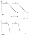
- This makes it possible to use the front area Machine speed following sheet 3 over the rear area of the previous sheet 3a to pull, which is still on the sheet brake 6, the holds the sheet 3a in its rear area and with one opposite the Transport speed of the sheet 3 is operated at reduced speed. It this results in a time saving in the order of magnitude of the comparison of the Velocity-time diagrams in Figures 2 and 3 after a sheet braking the inventive method ( Figure 2) and a conventional Sheet braking ( Figure 3).
- the one available for sheet braking Time window is increased considerably because the time of the sheet deceleration in the Area that can be extended by the overlap formed by the scaling.
- the sheet brake 6 can be designed as a mechanical sheet brake and for example, from suction belts rotating side by side, a suction roller or the like exist, but with a compared to the speed of Sheet transport to the delivery runs at a lower speed.
- the sheet brake 6 detects the sheet 3a in its rear area and at the same time forms an extension the levitation guide 4 for the following sheet 3, as can be seen clearly from the figure 1 results.
- the sheet brake 6 is arranged at a distance a - seen in the sheet transport direction - behind the floating guide 4, so that an exhaust air duct 9 is formed between these devices, which derives the air flow T generated by the floating guide 4 as soon as the end of the respective leading sheet 3a Opening cross-section of the exhaust duct 9 releases.
- the carrier air flow T is divided into two arms (T T , T A ). In this case, the air flow T T remaining between the bends 3 and 3a causes the separation of the successive bends 3, 3a, the other air flow T A being conducted into the exhaust air duct 9.
- a sheet 3 fed to the delivery by means of a gripper closure is fed to the sheet brake 6 on a carrier air stream T.
- the - seen in the sheet transport direction - arranged behind the levitation guide 4 sheet brake 6 is arranged essentially at the same level as the levitation guide 4, in a preferred embodiment, the height difference between the levitation guide 4 and sheet brake 6 is the substrate thickness d.
- the distance a between the levitation guide 4 and the sheet brake 6 determines the outlet cross section of the exhaust air duct 9.
- the sheet stack 10 is essentially with its storage surface (top sheet) arranged at a level with the levitation guide 4 and the sheet brake 6, preferably by the substrate thickness d lower than the sheet brake 6.
- the floating guide becomes a carrier air flow T with at least one Speed components in the direction of movement of the bow 3,3a in the direction of Bow brake 6 rinsed.
- This speed component has an amount of approx. 50% to 150% of the conveying speed of the sheet 3.3a.
- the sheet 3 is held with its front edge in the gripper system 1, 2 and Sheet brake 6 supplied. This floats on a carrier air stream T at a distance H above the floating guide 4. At this time there is 6 on the sheet brake the leading sheet 3a, which is already at a reduced speed on the Sheet stack 10 is transported. This leading sheet 3a forms the Extension of the control level formed by the floating guide 4. Thus the Sheet 3 already drawn over sheet brake 6 without the sheet 3a leading ahead touch or without coming into contact with the sheet brake 6.
- the leading sheet 3a releases the air outlet opening of the exhaust air duct 9.
- the carrier air T is divided into a partial flow T A , which is discharged via the exhaust duct 9 and a partial flow T T , which ensures the separation between the two bends 3, 3 a.
- the exhaust air duct 9 is completely released from the leading sheet 3a, so that the exhaust air flow T A becomes larger and the separation air flow T T becomes smaller.
- one end of the sheet 3 reaches the sheet brake 6 released by the leading sheet 3a.
- the gripper 2 opens and also releases the front edge of the sheet 3.
- the sheet is now located with the rear edge on the sheet brake 6, while the front area floats on the air cushion T T which has been washed in previously. This cushion gradually escapes between the sheet 3a located on the sheet stack 10, so that contact only takes place when no more translatory movement is carried out.
Landscapes
- Engineering & Computer Science (AREA)
- Mechanical Engineering (AREA)
- Delivering By Means Of Belts And Rollers (AREA)
- Separation, Sorting, Adjustment, Or Bending Of Sheets To Be Conveyed (AREA)
- Sheets, Magazines, And Separation Thereof (AREA)
- Discharge By Other Means (AREA)
Applications Claiming Priority (4)
| Application Number | Priority Date | Filing Date | Title |
|---|---|---|---|
| DE19527440 | 1995-07-27 | ||
| DE19527440 | 1995-07-27 | ||
| DE19626369 | 1996-07-02 | ||
| DE19626369A DE19626369C2 (de) | 1995-07-27 | 1996-07-02 | Verfahren und Vorrichtung zum Bogenabbremsen im Ausleger einer Bogenrotationsdruckmaschine |
Publications (3)
| Publication Number | Publication Date |
|---|---|
| EP0755888A2 EP0755888A2 (de) | 1997-01-29 |
| EP0755888A3 EP0755888A3 (de) | 1997-08-27 |
| EP0755888B1 true EP0755888B1 (de) | 1999-12-29 |
Family
ID=26017187
Family Applications (1)
| Application Number | Title | Priority Date | Filing Date |
|---|---|---|---|
| EP96112088A Expired - Lifetime EP0755888B1 (de) | 1995-07-27 | 1996-07-26 | Verfahren und Vorrichtung zum Bogenabbremsen im Ausleger einer Bogenrotationsdruckmaschine |
Country Status (5)
| Country | Link |
|---|---|
| US (1) | US5740740A (enExample) |
| EP (1) | EP0755888B1 (enExample) |
| JP (1) | JP3625582B2 (enExample) |
| CN (1) | CN1090564C (enExample) |
| AT (1) | ATE188188T1 (enExample) |
Families Citing this family (9)
| Publication number | Priority date | Publication date | Assignee | Title |
|---|---|---|---|---|
| US6209456B1 (en) * | 1996-03-13 | 2001-04-03 | Heidelberger Druckmaschinen Ag | Web- and sheet-fed printing unit using various ink types, particularly water-based inks |
| US6305772B1 (en) | 1997-06-25 | 2001-10-23 | Unisys Corporation | Angled air impingment system for document control |
| CN1084253C (zh) * | 1999-01-19 | 2002-05-08 | 李青安 | 无叼纸自动快速续纸系统 |
| US20030131943A1 (en) * | 2002-01-17 | 2003-07-17 | Frederisy Douglas R. | Apparatus and method for assembling absorbent garments |
| JP2007245719A (ja) * | 2006-03-15 | 2007-09-27 | Heidelberger Druckmas Ag | 枚葉紙搬送装置 |
| DE102013010943B4 (de) * | 2012-07-26 | 2024-03-14 | Heidelberger Druckmaschinen Ag | Bogenleitvorrichtung |
| CN103419483A (zh) * | 2013-08-30 | 2013-12-04 | 新乡市瑞博印刷包装机械有限公司 | 胶印机空气托纸收纸装置 |
| JP6723722B2 (ja) * | 2014-12-02 | 2020-07-15 | キヤノン株式会社 | シート搬送装置、及び画像形成装置 |
| CN111605764B (zh) * | 2020-06-04 | 2021-10-29 | 青岛欣欣向荣智能设备有限公司 | 气流穿带打包机及其打包方法 |
Family Cites Families (9)
| Publication number | Priority date | Publication date | Assignee | Title |
|---|---|---|---|---|
| GB901906A (en) * | 1958-12-15 | 1962-07-25 | Linotype Machinery Ltd | Improvements relating to sheet delivery for printing machines |
| US3975012A (en) * | 1974-11-04 | 1976-08-17 | Maxson Automatic Machinery Company | Overlapped sheet-feeding machine |
| DE2544566C3 (de) * | 1975-10-04 | 1984-11-15 | Miller Printing Equipment Corp., Pittsburgh, Pa. | Bogenausleger für Bogendruckmaschinen |
| DE3938863A1 (de) * | 1989-11-24 | 1991-05-29 | Roland Man Druckmasch | Vorrichtung zum fuehren frisch bedruckter bogen, vorzugsweise in der auslage von druckmaschinen |
| DE4140253A1 (de) * | 1991-12-06 | 1993-06-09 | Heidelberger Druckmaschinen Ag, 6900 Heidelberg, De | Bogenleitvorrichtung im auslegebereich einer bogendruckmaschine |
| DE4308276C2 (de) * | 1993-03-16 | 1997-09-04 | Heidelberger Druckmasch Ag | Leiteinrichtung für einen Bogen |
| DE4343713C2 (de) * | 1993-12-21 | 1997-03-27 | Heinen Elektronik Gmbh | Ablage für von einer Transportanlage zwangsgeführte, in Reihe ankommende Bögen |
| DE4344040C1 (de) * | 1993-12-23 | 1995-03-23 | Kba Planeta Ag | Pneumatische Bogenleiteinrichtung |
| DE4433644B4 (de) * | 1994-09-21 | 2005-03-03 | Heidelberger Druckmaschinen Ag | Verfahren und Vorrichtung zur Führung eines Bogens |
-
1996
- 1996-07-26 AT AT96112088T patent/ATE188188T1/de not_active IP Right Cessation
- 1996-07-26 EP EP96112088A patent/EP0755888B1/de not_active Expired - Lifetime
- 1996-07-26 JP JP19769996A patent/JP3625582B2/ja not_active Expired - Fee Related
- 1996-07-29 CN CN96109203A patent/CN1090564C/zh not_active Expired - Fee Related
- 1996-07-29 US US08/681,819 patent/US5740740A/en not_active Expired - Fee Related
Also Published As
| Publication number | Publication date |
|---|---|
| ATE188188T1 (de) | 2000-01-15 |
| JPH09104556A (ja) | 1997-04-22 |
| CN1090564C (zh) | 2002-09-11 |
| EP0755888A2 (de) | 1997-01-29 |
| US5740740A (en) | 1998-04-21 |
| JP3625582B2 (ja) | 2005-03-02 |
| CN1148008A (zh) | 1997-04-23 |
| EP0755888A3 (de) | 1997-08-27 |
Similar Documents
| Publication | Publication Date | Title |
|---|---|---|
| DE2518373C2 (de) | Einrichtung zum Vergleichmässigen der gegenseitigen Abstände von in einem Schuppenstrom aufeinanderfolgenden Druckprodukten | |
| EP0707556B1 (de) | Vorrichtung zum transport und zur ablage von bogen in einem auslagebereich einer rotationsbogendruckmaschine | |
| EP0073388A2 (de) | Vorrichtung zum Ändern der Bewegungsrichtung von Briefen und ähnlichen rechteckigen Sendungen | |
| DE4435988A1 (de) | Vorrichtung zum Abbremsen von Bogen | |
| EP0755888B1 (de) | Verfahren und Vorrichtung zum Bogenabbremsen im Ausleger einer Bogenrotationsdruckmaschine | |
| DE102021118468B3 (de) | Maschinenanordnung mit mehreren jeweils Bogen bearbeitenden Bearbeitungsstationen | |
| EP0453805A1 (de) | Bogenleiteinrichtung im Auslegerbereich einer Bogenrotationsdruckmaschine | |
| EP0755887B1 (de) | Verfahren und Vorrichtung zum pneumatischen Bogenabbremsen im Ausleger einer Bogenrotationsdruckmaschine | |
| DE102004007404A1 (de) | Bogenhinterkanten-Anhebung | |
| EP1108671A2 (de) | Bogenbremssystem für einen Ausleger einer Bogen verarbeitenden Maschine | |
| EP0225994B1 (de) | Verfahren und Vorrichtung zum Abbremsen und Auslegen von in einer Druckmaschine bedruckten Bogen oder Bogenpaketen | |
| DD141150B1 (de) | Blaseinrichtung in bogenauslegern von bogenverarbeitenden maschinen | |
| DD140135A1 (de) | Einrichtung zum ablegen von bogen an bogenauslegern | |
| US5909873A (en) | Non marking slow down apparatus | |
| DE10131607A1 (de) | Ausleger einer flächige Bedruckstoffe verarbeitenden Maschine | |
| DE4433644B4 (de) | Verfahren und Vorrichtung zur Führung eines Bogens | |
| DD239987A1 (de) | Einrichtung zur foerderung der bogen in auslegern von bogendruckmaschinen | |
| DE19626369C2 (de) | Verfahren und Vorrichtung zum Bogenabbremsen im Ausleger einer Bogenrotationsdruckmaschine | |
| DE2720674A1 (de) | Bogenauslegevorrichtung fuer eine rotations-druckmaschine | |
| EP0257366B1 (de) | Vorrichtung zur registerhaltigen Anlage eines Bogens im Anlegeblech einer Rotationsdruckmaschine | |
| DE4211381C2 (de) | Leiteinrichtung in einer Bogendruckmaschine | |
| EP1138623B1 (de) | Ausleger einer Bogen verarbeitenden Maschine | |
| DE10239709B4 (de) | Einrichtung zur Ablage von Bogen im Ausleger einer bogenverarbeitenden Maschine | |
| DE10304617A1 (de) | Bogenförderer für eine Bogen verarbeitende Maschine | |
| DE102021006551A1 (de) | Maschinenanordnung mit mehreren jeweils Bogen bearbeitenden Bearbeitungsstationen |
Legal Events
| Date | Code | Title | Description |
|---|---|---|---|
| PUAI | Public reference made under article 153(3) epc to a published international application that has entered the european phase |
Free format text: ORIGINAL CODE: 0009012 |
|
| 17P | Request for examination filed |
Effective date: 19960726 |
|
| AK | Designated contracting states |
Kind code of ref document: A2 Designated state(s): AT CH DE FR GB LI SE |
|
| PUAL | Search report despatched |
Free format text: ORIGINAL CODE: 0009013 |
|
| AK | Designated contracting states |
Kind code of ref document: A3 Designated state(s): AT CH DE FR GB LI SE |
|
| 17Q | First examination report despatched |
Effective date: 19980218 |
|
| GRAG | Despatch of communication of intention to grant |
Free format text: ORIGINAL CODE: EPIDOS AGRA |
|
| GRAG | Despatch of communication of intention to grant |
Free format text: ORIGINAL CODE: EPIDOS AGRA |
|
| GRAH | Despatch of communication of intention to grant a patent |
Free format text: ORIGINAL CODE: EPIDOS IGRA |
|
| GRAH | Despatch of communication of intention to grant a patent |
Free format text: ORIGINAL CODE: EPIDOS IGRA |
|
| GRAA | (expected) grant |
Free format text: ORIGINAL CODE: 0009210 |
|
| AK | Designated contracting states |
Kind code of ref document: B1 Designated state(s): AT CH DE FR GB LI SE |
|
| PG25 | Lapsed in a contracting state [announced via postgrant information from national office to epo] |
Ref country code: SE Free format text: THE PATENT HAS BEEN ANNULLED BY A DECISION OF A NATIONAL AUTHORITY Effective date: 19991229 |
|
| REF | Corresponds to: |
Ref document number: 188188 Country of ref document: AT Date of ref document: 20000115 Kind code of ref document: T |
|
| REG | Reference to a national code |
Ref country code: CH Ref legal event code: EP |
|
| REF | Corresponds to: |
Ref document number: 59604018 Country of ref document: DE Date of ref document: 20000203 |
|
| GBT | Gb: translation of ep patent filed (gb section 77(6)(a)/1977) |
Effective date: 20000225 |
|
| ET | Fr: translation filed | ||
| PG25 | Lapsed in a contracting state [announced via postgrant information from national office to epo] |
Ref country code: AT Free format text: LAPSE BECAUSE OF NON-PAYMENT OF DUE FEES Effective date: 20000726 |
|
| PLBE | No opposition filed within time limit |
Free format text: ORIGINAL CODE: 0009261 |
|
| STAA | Information on the status of an ep patent application or granted ep patent |
Free format text: STATUS: NO OPPOSITION FILED WITHIN TIME LIMIT |
|
| 26N | No opposition filed | ||
| REG | Reference to a national code |
Ref country code: GB Ref legal event code: IF02 |
|
| PGFP | Annual fee paid to national office [announced via postgrant information from national office to epo] |
Ref country code: FR Payment date: 20020719 Year of fee payment: 7 |
|
| PGFP | Annual fee paid to national office [announced via postgrant information from national office to epo] |
Ref country code: CH Payment date: 20020730 Year of fee payment: 7 |
|
| PGFP | Annual fee paid to national office [announced via postgrant information from national office to epo] |
Ref country code: GB Payment date: 20030623 Year of fee payment: 8 |
|
| PG25 | Lapsed in a contracting state [announced via postgrant information from national office to epo] |
Ref country code: LI Free format text: LAPSE BECAUSE OF NON-PAYMENT OF DUE FEES Effective date: 20030731 Ref country code: CH Free format text: LAPSE BECAUSE OF NON-PAYMENT OF DUE FEES Effective date: 20030731 |
|
| REG | Reference to a national code |
Ref country code: CH Ref legal event code: PL |
|
| PG25 | Lapsed in a contracting state [announced via postgrant information from national office to epo] |
Ref country code: FR Free format text: LAPSE BECAUSE OF NON-PAYMENT OF DUE FEES Effective date: 20040331 |
|
| REG | Reference to a national code |
Ref country code: FR Ref legal event code: ST |
|
| PG25 | Lapsed in a contracting state [announced via postgrant information from national office to epo] |
Ref country code: GB Free format text: LAPSE BECAUSE OF NON-PAYMENT OF DUE FEES Effective date: 20040726 |
|
| PGFP | Annual fee paid to national office [announced via postgrant information from national office to epo] |
Ref country code: DE Payment date: 20040809 Year of fee payment: 9 |
|
| GBPC | Gb: european patent ceased through non-payment of renewal fee |
Effective date: 20040726 |
|
| PG25 | Lapsed in a contracting state [announced via postgrant information from national office to epo] |
Ref country code: DE Free format text: LAPSE BECAUSE OF NON-PAYMENT OF DUE FEES Effective date: 20060201 |