EP0743384A2 - Verfahren und Vorrichtung zur Steuerung des Gebrauches von Druckluft in Düsenwebmaschinen - Google Patents
Verfahren und Vorrichtung zur Steuerung des Gebrauches von Druckluft in Düsenwebmaschinen Download PDFInfo
- Publication number
- EP0743384A2 EP0743384A2 EP96104289A EP96104289A EP0743384A2 EP 0743384 A2 EP0743384 A2 EP 0743384A2 EP 96104289 A EP96104289 A EP 96104289A EP 96104289 A EP96104289 A EP 96104289A EP 0743384 A2 EP0743384 A2 EP 0743384A2
- Authority
- EP
- European Patent Office
- Prior art keywords
- pressure
- air supply
- jet loom
- compressed air
- compressed
- Prior art date
- Legal status (The legal status is an assumption and is not a legal conclusion. Google has not performed a legal analysis and makes no representation as to the accuracy of the status listed.)
- Granted
Links
- 238000000034 method Methods 0.000 title claims abstract description 11
- 230000002401 inhibitory effect Effects 0.000 claims description 5
- 238000003780 insertion Methods 0.000 description 17
- 230000037431 insertion Effects 0.000 description 17
- 230000001105 regulatory effect Effects 0.000 description 8
- 230000002159 abnormal effect Effects 0.000 description 7
- 238000001514 detection method Methods 0.000 description 7
- 238000010586 diagram Methods 0.000 description 7
- 230000005856 abnormality Effects 0.000 description 6
- 230000009471 action Effects 0.000 description 6
- 230000001276 controlling effect Effects 0.000 description 6
- 238000002347 injection Methods 0.000 description 6
- 239000007924 injection Substances 0.000 description 6
- 230000004044 response Effects 0.000 description 6
- 230000007423 decrease Effects 0.000 description 3
- 239000004744 fabric Substances 0.000 description 3
- 239000002759 woven fabric Substances 0.000 description 3
- 230000002950 deficient Effects 0.000 description 2
- 238000012986 modification Methods 0.000 description 2
- 230000004048 modification Effects 0.000 description 2
- 230000004913 activation Effects 0.000 description 1
- 230000015556 catabolic process Effects 0.000 description 1
- 238000006243 chemical reaction Methods 0.000 description 1
- 238000010276 construction Methods 0.000 description 1
- 230000010485 coping Effects 0.000 description 1
- 230000003247 decreasing effect Effects 0.000 description 1
- 238000006731 degradation reaction Methods 0.000 description 1
- 230000002265 prevention Effects 0.000 description 1
- 230000009467 reduction Effects 0.000 description 1
- 230000000630 rising effect Effects 0.000 description 1
- 230000001629 suppression Effects 0.000 description 1
- 238000009941 weaving Methods 0.000 description 1
Images

Classifications
-
- D—TEXTILES; PAPER
- D03—WEAVING
- D03D—WOVEN FABRICS; METHODS OF WEAVING; LOOMS
- D03D47/00—Looms in which bulk supply of weft does not pass through shed, e.g. shuttleless looms, gripper shuttle looms, dummy shuttle looms
- D03D47/28—Looms in which bulk supply of weft does not pass through shed, e.g. shuttleless looms, gripper shuttle looms, dummy shuttle looms wherein the weft itself is projected into the shed
- D03D47/30—Looms in which bulk supply of weft does not pass through shed, e.g. shuttleless looms, gripper shuttle looms, dummy shuttle looms wherein the weft itself is projected into the shed by gas jet
- D03D47/3026—Air supply systems
- D03D47/3053—Arrangements or lay out of air supply systems
-
- D—TEXTILES; PAPER
- D03—WEAVING
- D03D—WOVEN FABRICS; METHODS OF WEAVING; LOOMS
- D03D47/00—Looms in which bulk supply of weft does not pass through shed, e.g. shuttleless looms, gripper shuttle looms, dummy shuttle looms
- D03D47/28—Looms in which bulk supply of weft does not pass through shed, e.g. shuttleless looms, gripper shuttle looms, dummy shuttle looms wherein the weft itself is projected into the shed
- D03D47/30—Looms in which bulk supply of weft does not pass through shed, e.g. shuttleless looms, gripper shuttle looms, dummy shuttle looms wherein the weft itself is projected into the shed by gas jet
- D03D47/3026—Air supply systems
- D03D47/3033—Controlling the air supply
-
- D—TEXTILES; PAPER
- D03—WEAVING
- D03D—WOVEN FABRICS; METHODS OF WEAVING; LOOMS
- D03D51/00—Driving, starting, or stopping arrangements; Automatic stop motions
- D03D51/18—Automatic stop motions
- D03D51/44—Automatic stop motions acting on defective operation of loom mechanisms
Definitions
- the present invention relates to a method for controlling use of compressed air in a jet loom and a compressed-air supply/control apparatus for the jet loom.
- the air supplying means having a desired discharge pressure can operatively be connected to the selected jet loom(s) so that the air discharged at a desired pressure can be supplied to the jet loom.
- JP-A-3-104962 there is provided a controller which is supplied with pressure information signals from pressure regulators provided in association with a plurality of jet looms, respectively, together with pressure information signals outputted from pressure sensors provided in association with air tanks which are installed in compressed air Supplying passages.
- the controller is so designed or programmed as to arithmetically determine two theoretical basic pressure values differing from each other on the basis of maximum pressure values obtained from the plurality of pressure regulators to thereby compare the detected pressure values derived from the outputs of the pressure sensors with the two theoretical basic pressure values.
- the controller turns off the air compressor (i.e., stops operation of the compressor), while the controller turns on (i.e., puts into operation) the compressor, when the detected pressure is lower than the theoretical basic pressure of smaller value.
- the compressed-air supply pressure is so regulated as to fall within a range defined by the two theoretical basic values.
- Another object of the invention is to provide an apparatus for carrying out the method mentioned above.
- an air supply pressure of compressed air supplied to a jet loom from a compressed-air supply apparatus is detected and compared with a preset reference pressure, wherein use of the compressed air in the jet loom is disabled when the detected air supply pressure becomes lower than the preset reference pressure.
- an air supply pressure of compressed air supplied to a jet loom from a compressed-air supply apparatus is detected and then a period during which the detected air supply pressure is lower than a preset reference pressure is detected to be subsequently compared with a preset reference period, wherein use of the compressed air in the jet loom is disabled when the detected period reaches or exceeds the reference period.
- operation of the jet loom may be stopped substantially concurrently with the stoppage of the compressed air supply.
- the stoppage of use of the compressed air in the jet loom is so interlocked with stoppage of the loom operation that the weft inserting operation is inhibited upon stoppage of the loom operation.
- a pressure of compressed air supplied to a jet loom from a compressed-air supply apparatus is detected to be subsequently compared with a preset reference pressure, wherein use of the compressed air in the jet loom is enabled when the detected air supply pressure is higher than the preset reference pressure.
- the weft inserting operation in the jet loom is started only after the compressed air supply pressure exceeds the preset pressure level, whereby occurrence of abnormality in the jet loom due to abnormal lowering of the compressed air supply pressure can effectively be excluded.
- such arrangement may be adopted that the use of the compressed air in the jet loom is enabled substantially concurrently with starting of operation of the jet loom.
- a compressed-air supply apparatus for a jet loom, which apparatus includes a compressor for producing compressed air to be supplied to the jet loom, a pressure detecting means for detecting an air supply pressure at which the compressed air is supplied to the jet loom from the compressor through an air flow passage, a comparison means for comparing the air supply pressure detected by the pressure detecting means with a preset reference pressure, and a disabling decision means for issuing an inhibit signal for disabling the use of the compressed air in the jet loom when the air supply pressure detected by the pressure detecting means becomes lower than the preset reference pressure level.
- the weft inserting operation effected under the action of jet(s) of the compressed air is stopped when the detected compressed air supply pressure becomes lower than the preset level, whereby defective weft insertion due to the pressure lowering of the air jet(s) can effectively be suppressed.
- the jet loom can be protected against abnormality which say otherwise be brought about due to abnormal lowering of the compressed air supply pressure.
- a compressed-air supply apparatus for a jet loom, which apparatus includes a compressor for producing a compressed air to be supplied to the jet loom, a pressure detecting means for detecting an air supply pressure at which the compressed air is supplied to the jet loom from the compressor through an air flow passage, a period detecting means for detecting a period during which the compressed air supply pressure detected by the pressure detecting means remains lower than a preset reference pressure, a period comparing means for comparing the period detected by the period detecting means with a preset reference period, and a use disabling decision means for issuing an inhibit signal for inhibiting use of the compressed air in the jet loom when it is detected as a result of the period comparison that the period detected by the period detecting means exceeds the preset reference period.
- the signal for inhibiting use of the compressed air may serve additionally as a signal for stopping operation of the jet loom.
- a compressed-air supply apparatus for a jet loom, which apparatus includes a compressor for producing a compressed air to be supplied to the jet loom, a pressure detecting means for detecting an air supply pressure at which the compressed air is supplied to the jet loom from the compressor through an air flow passage, a comparison means for comparing the air supply pressure detected by the pressure detecting means with a preset reference pressure, and a use enabling decision means for issuing an enable signal for enabling use of the compressed air in the jet loom when the air supply pressure detected by the pressure detecting means exceeds the preset reference pressure level.
- the weft inserting operation in the jet loom is started only after the compressed air supply pressure exceeds the preset pressure level, whereby occurrence of abnormality in the jet loom due to abnormal lowering of the compressed air supply pressure can effectively be excluded.
- the signal for enabling the use of the compressed air may serve additionally as a signal for enabling operation of the jet loom.
- the use enabling decision means may be so arranged as to decide whether the use enabling signal for enabling the use of the compressed air is to be issued or not on the basis of the information which is supplied from status signal transmitting means and which indicates status of use of the compressed air in the jet loom.
- the status of use of the compressed air in the jet loom is transmitted or informed to the use enabling decision means through the use status information signal transmitting means.
- the use enabling decision means enables use of the compressed air only after the compressed air supply pressure exceeds the preset pressure level.
- a first referred mode for carrying out the invention i.e., a first exemplary embodiment thereof.
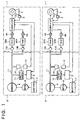
- Fig. 1 is a block diagram showing schematically a compressed-air supply control system for e.g., two jet looms provided for parallel operations independent of each other. That is, the compressed air supply control system comprises two subsystems each operatively associated with the corresponding air jet looms.
- each of the air jet looms (hereinafter referred to simply as the jet loom in abbreviation) generally designated by a reference numeral 1 is provided with a loom driving motor 2 which is under the control of a loom control computer C 0 serving also as a speed control command means.
- the loom control computer C 0 responds to a turning-on or closing operation of a starting switch 3 constituting a starting means, to thereby perform an operation control of the loom driving motor 2 and energization/deenergization controls of solenoid-operated on/off valve devices 4A and 4B.
- a weft is inserted into an inter-warp opening under the action of air jet injected by a weft inserting main nozzle (not shown), wherein the weft inserted into the inter-warp opening is caused to run therethrough under the action of air jets injected successively and sequentially in a relay-like fashion by means of a plurality of auxiliary nozzles (not shown ).
- a weft inserting main nozzle not shown
- reference character 4A designates a solenoid-operated on/off valve device (also referred to as an electromagnetic change-over valve device) which serves for controlling the supply of compressed air to the weft inserting main nozzle (i.e., changing over the air supplying state and the air-supply stopped state for the weft inserting main nozzle) while reference character 4B designates a solenoid-operated on/off valve for controlling the supply of the compressed air to the weft inserting auxiliary nozzles.
- the weft inserting main nozzle (not shown) is connected in series to the solenoid-operated on/off valve device 4A, a main compressed-air tank 20A and a pressure regulator 13A.
- the weft inserting auxiliary nozzles (not shown ) are connected in series to the solenoid-operated on/off valve device 4B, an auxiliary compressed-air tank 20B and a pressure regulator 13B.
- a reference numeral 5 generally designates a compressed-air supply/control apparatus which is destined to be employed in association with the jet loom 1 on a one-by-one basis.
- the compressed-air supply/control apparatus 5 is comprised of a discharge flow rate determining circuit 6, an inverter 7 constituting a part of a discharge flow rate change-over means, a pulse motor 8 also constituting a part of the discharge flow rate change-over means, an air compressor 9 of a fixed capacity type, a pressure-responsive on/off switch 10 which is employed as a pressure detecting means and a disabling decision circuit 14.
- the pressure-responsive on/off switch 10 is so arranged as to detect the pressure within a compressed air supplying passage 11 which extends from the air compressor 9 of the fixed capacity type to the jet loom 1.
- the pressure-responsive on/off switch 10 when the pressure within the compressed air supplying passage 11 becomes equal to or exceeds a first reference pressure P 1 , the pressure-responsive on/off switch 10 is turned off. This state (i.e., off-state) is held until the pressure within the compressed air supplying passage 11 has reduced to a second reference pressure P 2 ( ⁇ P 1 ). When the pressure of the compressed air supplying passage 11 becomes equal to or lower than the second reference pressure P 2 , the pressure-responsive on/off switch 10 is then turned on. This on-state of the switch 10 is held until the pressure of the compressed air supplying passage 11 has increased up to the first reference pressure P 1 .
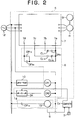
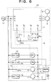
- Fig. 2 shows an electric control circuit for the compressed-air supply/control apparatus 5.
- the inverter 7 which serves as a frequency converter outputs to the pulse motor 8 an electric power of a pulse frequency resulting from a frequency conversion of the output power of a three-phase AC power source 12.
- the pulse motor 8 (which may also be referred to as the variable-speed motor) is designed to rotate at a rotation speed (rpm) which is in proportion to the pulse frequency of the electric power supplied from the inverter 7, while the air compressor 9 of fixed capacity type operates to discharge an amount of compressed air which depends on the rotation speed of the pulse motor 8. Consequently, the discharged air flow rate in the compressed air supplying passage 11 per unit time increases as the rotation speed of the pulse motor 8 increases.
- a status information transmitting switch 3A constituting a part of the discharge flow rate determining circuit 6 is adapted to operate in response to on/off commands issued from the loom control computer C 0 . More specifically, the loom control computer C 0 closes or turns on the status information transmitting switch 3A in response to the turn-on operation of the starting switch 3. On the other hand, when an operation stop signal S (see Fig. 3) is inputted to the loom control computer C 0 , the status information transmitting switch 3A is tuned off by the loom control computer C 0 .
- the air-use disabling decision circuit 14 (see Fig. 2) is comprised of an normally opened contact OP 14 and a period detecting circuit 15.
- the period detecting circuit 15 When a closed state of the normally opened contact OP 14 continues for a period longer than a preset period T 1 from a time point when the normally opened contact OP 14 is changed over to the closed state from the open state, the period detecting circuit 15 outputs the operation stop signal S to the loom control computer C 0 .
- the inverter 7 is provided with a common terminal 7a together with a predetermined number (three in the illustrated apparatus) of converted-frequency selecting terminals 7b, 7c and 7d.
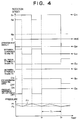
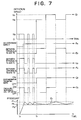
- a curve E 1 illustrated in Fig. 3 represents graphically the rotation speed of the air compressor 9 of the fixed capacity type.
- a curve E 2 illustrated in Fig. 3 represents graphically change-over of an electrical connection with an electrical disconnection between the terminals 7a and 7b.
- a curve E 3 in Fig. 3 represents graphically change-over of an electrical connection with an electrical disconnection between the terminals 7a and 7c.
- a curve E 4 in Fig. 3 represents graphically change-over of an electrical connection with an electrical disconnection between the terminals 7a and 7d.
- the inverter 7 When the electric connection is formed neither between the terminals 7a and 7b, the terminals 7a and 7c nor between the terminals 7a and 7d, the inverter 7 outputs no electric power. In the state where the terminals 7a and 7b are disconnected while the electric connections are formed between the terminals 7a and 7c and between the terminals 7a and 7d, respectively, the inverter 7 outputs the electric power of a converted frequency which is effective to set the rotation speed of the inverter 7 to a speed N 3 (rpm).
- the inverter when the terminals 7a and 7b on one hand and the terminals 7a and 7d on the other hand are electrically connected, respectively, with the terminals 7a and 7c being electrically disconnected, the inverter outputs the electric power of a converted pulse frequency which sets the rotation speed of the air compressor 9 to a second rotation speed N 2 (> N 3 ). Furthermore, in the state where electrical disconnection exists between the terminals 7a and 7b and between the terminals 7a and 7c with the terminals 7a and 7d being electrically connected to each other, the inverter 7 outputs the electric power of a converted pulse frequency for setting the rotation speed of the air compressor 9 to the first rotation speed N 1 (> N 2 ).
- a curve E 5 represents the on/off state of the status information transmitting switch 3A (see Fig. 2).
- the on-off state of the status information transmitting switch 3A corresponds to that of the starting switch 3.
- a curve E 6 shown in Fig. 3 represents the on/off state of the pressure-responsive on/off switch 10, while a curve E 7 represents variation of the pressure within the compressed air supplying passage 11.
- the pressure-responsive on/off switch 10 assumes the closed state (i.e., the on-state).
- the three-phase AC power source 12 is turned on at a time point t 0 .
- the relay CR 1 is electrically energized, whereby the normally closed contact CL 11 is opened while the normally opened contacts OP 12 and OP 13 are closed (i.e., turned on).
- the terminals 7a and 7b are electrically disconnected from each other, while electrical connections are formed between the terminals 7a and 7c and between the terminals 7a and 7d, respectively.
- the air compressor 9 starts to rotate at the rotation speed N 3 , which results in that the compressed air is supplied to the jet loom 1 by way of the compressed air supplying passage 11.
- a straight line E 8 indicates that the operation stop signal S is not outputted from the period detecting circuit 15.
- the pressure-responsive on/off switch 10 When the pressure within the compressed air supplying passage 11 exceeds the first reference pressure P 1 , the pressure-responsive on/off switch 10 is turned off (i.e., opened state), causing the relay CR 1 to be electrically deenergized.
- the normally closed contact CL 11 Upon deenergization of the relay CR 1 , the normally closed contact CL 11 is closed with the normally opened contacts OP 12 and OP 13 being opened. In this state, there prevails electrically disconnected states between the terminals 7a and 7b, between the terminals 7a and 7c and between the terminals 7a and 7d, respectively.
- the inverter 7 stops outputting the pulse frequency electric power, to thereby stop the operation of the compressor 9.
- the compressed air within the compressed air supplying passage 11 is supplied to the weft inserting main nozzle by way of the pressure regulator 13.
- the pressure regulator 13 is set at a considerably lower pressure P 0 than the second reference pressure P 2 .
- the pressure of the compressed air which is higher than the pressure P 0 is lowered to the pressure P 0 , whereupon the compressed air is supplied to the weft inserting main nozzle.
- the air as supplied is jetted from the weft inserting main nozzle at the pressure P 0 . Because the pressure P 0 is low, the posture of the tip end portion of the weft in the standby state is rectified into a linear form under the action of the air jet, which contributes to suppression of occurrence of error or fault in the weft insertion.
- the pressure within the compressed air supplying passage 11 decreases. In that case, when the pressure within the compressed air supplying passage 11 becomes lower than the second reference pressure P 2 , the pressure-responsive on/off switch 10 is turned on, to thereby start rotation of the air compressor 9 at the rotation speed N 3 .
- the status information transmitting switch 3A is in the off-state, i.e., when the starting switch 3 is opened (OFF) to say in another way, the pressure within the compressed air supplying passage 11 is regulated to a level intermediate between the first reference pressure P 1 and the second reference pressure P 2 .
- the status information transmitting switch 3A is closed or turned on.
- the pressure within the compressed air supplying passage 11 at the time point t 1 is reduced with no electric connections being formed between the terminals 7a and 7b, between terminals 7a and 7c and between the terminals 7a and 7d. Consequently, the air compressor 9 is in the inoperative state.
- the relay CR 2 is electrically energized to close the normally opened contacts OP 21 and OP 23 while opening the normally closed contact CL 22 .
- the loom control computer C 0 activates the loom driving motor 2 while performing electric energization/deenergization of the solenoid-operated on/off valve devices 4A and 4B.
- the weft inserting main nozzle and the weft inserting auxiliary nozzles produce air jets at predetermined rotation angular positions, respectively, during every rotation of the jet loom 1. Under the actions of these air jets, insertion of the weft is carried out.
- the consumption of the compressed air used in the jet loom for the weft inserting air injections will exceed an amount of the compressed air supplied from the air compressor 9 operating at the second rotation speed N 2 , which involves gradual lowering of the pressure within the compressed air supplying passage 11.
- the relay CR 1 is electrically energized.
- the normally closed contacts CL 11 and CL 22 are opened while the normally opened contacts OP 12 , OP 13 , OP 21 and OP 23 are closed.
- the air compressor 9 is caused to rotate at the first rotation speed N 1 .
- the consumption of the compressed air as brought about by injection of the air jets from the weft inserting main nozzle and the weft inserting auxiliary nozzles is smaller than the amount of compressed air supplied from the air compressor 9 operating at the first rotation speed N 1 .
- the pressure within the compressed air supplying passage 11 rises progressively.
- the relay CR 1 When the pressure within the compressed air supplying passage 11 rises beyond the first reference pressure P 1 , the relay CR 1 is electrically deenergized. Thus, the state in which both the relays CR 1 and CR 2 are electrically energized is changed over to the state where the relay CR 1 is deenergized with the relay CR 2 being energized, whereby the rotation speed of the air compressor 9 decreases from the first rotation speed N 1 to the second rotation speed N 2 . Owing to such lowering of the rotation speed, the pressure within the compressed air supplying passage 11 decreases gradually from the first reference pressure P 1 toward the second reference pressure P 2 . Thus, it is safe to say that the pressure within the compressed air supplying passage 11 in the state in which the starting switch 3 is closed is regulated to a level intermediate between the first reference pressure P 1 and the second reference pressure P 2 .
- the discharge flow rate determining circuit 6 serves to control the rotation speed of the pulse motor 8 selectively at four speed stages or levels in dependence on the on/off states of the status information transmitting switch 3A which constitutes an operation status transmit means for transmitting or informing the pressure detection state of the pressure-responsive on/off switch 10 and the operation status of the jet loom 1. More specifically, when the starting switch 3 is in the off-state, the discharge flow rate determining circuit 6 determines either a discharge flow rate regulating mode in which the rotation speed of the air compressor 9 is set to zero or a discharge flow rate regulating mode in which the rotation speed of the air compressor 9 is set to the rotation speed N 3 on the basis of the result of comparison between the two reference pressures P 1 and P 2 and the detected pressure.
- the discharge flow rate determining circuit 6 determines either a first discharge flow rate regulating mode in which the rotation speed of theair compressor 9 is set to the second rotation speed N 2 or alternatively a second discharge flow rate regulating mode in which the rotation speed of the air compressor 9 is set to the first rotation speed N 1 on the basis of the result of comparison between the two reference pressures P 1 and P 2 and the detected pressure.
- the difference or gap between the reference pressures P 1 and P 2 can be decreased, whereby the range defined by the reference pressures P 1 and P 2 can be regulated to such a range in which variation in the weft inserting air injection pressure can provide no obstacle to a satisfactory weft insertion.
- variation in the pressure within the compressed air supplying passage 11 is limited to the range defined between the reference pressures P 1 and P 2 , whereby steep lowering of the compressed air supply pressure can positively be suppressed.
- the reference pressures P 1 and P 2 are determined in consideration of the types of the weft, the rotation speed of the jet loom and others. It is however desirable to alter or update the rotation speed of the air compressor 9 when the reference pressures P 1 and P 2 are changed.
- the use of the pulse motor 8 serving as a variable speed driving motor in combination with the inverter 7 constituting the discharge flow rate change-over means makes it easy to set selectively the rotation speed of the air compressor 9.
- a curve E 71 shown in Fig. 4 represents, by way of example only, a manner in which the compressed air supply pressure becomes lower without attaining the first reference pressure P 1 in the course of operation of the jet loom 1.
- the pressure-responsive on/off switch 10 is closed (i.e., turned on)
- the relay CR 1 is electrically energized, whereby the normally opened contact OP 14 is closed.
- the period detecting circuit 15 When the on-state (closed state) of the normally opened contact OP 14 is changed over to the off-state (opened state) within the preset period T 1 , the period detecting circuit 15 does not output the operation stop signal S. On the contrary, when the state in which the normally opened contact OP 14 continues to be in the on-state (closed state) over a time span longer than the preset period T 1 , the period detecting circuit 15 outputs the operation stop signal S.
- a curve E 81 shown in Fig. 4 indicates presence and absence of the operation stop signal S outputted from the period detecting circuit 15.
- curves E 11 , E 21 , E 31 , E 41 , E 51 and E 61 correspond to the curves E 1 , E 2 , E 3 , E 4 , E 5 and E 6 , respectively.
- the pressure-responsive on/off switch 10 is not turned off until the preset period T 1 has lapsed from the time point t 2 at which the pressure-responsive on/off switch 10 was closed. Consequently, the closed state (on-state) of the normally opened contact OP 14 continues to exist beyond the preset period T 1 . Consequently, the period detecting circuit 15 issues the operation stop signal S to the loom control computer C 0 at a time point t 3 after lapse of the preset period T 1 from the time point t 2 .
- the loom control computer C 0 In response to the inputting of the operation stop signal S, the loom control computer C 0 issues a command for stopping operation of the loom driving motor 2 as well as a command for electrically deenergizing the solenoid-operated on/off valve device 4, while turning off the status information transmitting switch 3A.
- the relay CR 2 is electrically deenergized, whereby the normally closed contact CL 22 is closed while the normally opened contacts OP 21 and OP 23 are opened, to thereby cause the pulse motor 8 to rotate at the rotation speed N 3 after the time point t 3 .
- air jets through the weft inserting main nozzle and a weft inserting auxiliary nozzle are interrupted with the operation of the jet loom 1 being stopped substantially concurrently.
- the use of the compressed air in the jet loom can be controlled properly such that the weft inserting air jets are interrupted upon occurrence of abnormal lowering of the compressed air supply pressure, whereby occurrence of error in the weft insertion or quality degradation of the woven fabric can be suppressed to a possible minimum.
- the pressure-responsive on/off switch 10 for maintaining the compressed air pressure at an appropriate level within the pressure range of P 1 to P 2 is utilized for controlling properly the use or consumption status of the compressed air in the jet loom 1.
- the arrangement which allows the pressure-responsive on/off switch 10 to be used additionally for the control for establishing the effective utilization of the compressed air is advantageous in response to reduction of the total cost involved in implementing the compressed-air supply/control apparatus even when the pressure-responsive on/off switch 10 itself is expensive.
- employment of a single pressure detector contributes to significant simplification of the piping arrangement of the compressed air supplying passage 11 in the compressed air supplying system.
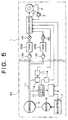
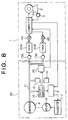
- the compressed air pressure within the compressed air supplying passage 11 is detected by a pressure-responsive on/off switch 16. More specifically, when the detected air supply pressure exceeds a preset pressure P 3 , the pressure-responsive on/off switch 16 is closed (i.e., turned on). In the case of the instant embodiment of the invention, the preset pressure P 3 is set slightly lower than the second reference pressure P 2 .
- An operation enabling decision circuit 17 responds to the on-state of the pressure-responsive on/off switch 16 to generate an operation enabling signal H.
- a curve E 9 shown in Fig. 7 illustrates presence/absence of the output of the operation enabling signal H. So long as the operation enabling signal H is inputted, the loom control computer C 0 assumes the state in which the on-signal from the starting switch 3 is validated. When the starting switch 3 in the standby state is closed or turned on, the loom control signal C 0 commands activation of the loom driving motor 2 as well as the electrical energization/deenergization of the solenoid-operated on/off valve devices 4A and 4B.
- the pressure-responsive on/off switch 16 does not output the on-signal to the operation enabling decision circuit 17.
- the operation enabling signal H is not outputted to the loom control signal C 0 from the decision circuit 17.
- the preset pressure P 3 is so set as to be only slightly lower than the second reference pressure P 2 .
- the air jet pressure for the weft insertion may be regarded as a suitable injection pressure when compressed air supply pressure is the preset pressure P 3 .
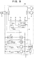
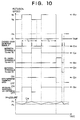
- Figs. 8 to 10 are views for illustrating the compressed-air supply/control apparatus for a jet loom according to a third embodiment of the present Invention.
- components or parts same as or equivalent to those of the compressed-air supply/control apparatus according to the second embodiment are designated by like reference characters. Accordingly, repeated description thereof is omitted.
- a pair of change-over detecting circuits 18 and 19 are provided for outputting change-over detection signals F generated in response to the on-and-off operations of the pressure-responsive on/off switch 10, respectively, to the operation disabling decision circuit 20.
- the change-over detecting circuit 18 is comprised of a normally opened contact OP 15 and a pulse signal output circuit 21.
- the change-over detecting circuit 19 is comprised of the normally closed contact CL 15 and a pulse signal output circuit 22. Every time the normally opened contact OP 15 is changed over from the opened state to the closed state, the pulse signal output circuit 21 outputs the pulse-like change-over detection signal F, while the pulse signal output circuit 22 outputs the pulse-like change-over detection signal every time the normally closed contact CL 15 is changed over from the opened state (off-state) to the closed state (on-state).
- a curve E 10 shown in Fig. 10 illustrates the presence/absence of the change-over detection signal F.
- the disabling decision circuit 20 When the interval at which the change-over detection signal F is inputted attains or exceeds the preset period T 2 , the disabling decision circuit 20 outputs the operation stop signal S to the loom control computer C 0 . Of course, unless the input interval of the change-over detection signal F reaches the preset period T 2 , the disabling decision circuit 20 does not issue the operation stop signal S. It is to be mentioned that the preset period T 2 is set longer than the interval at which the pressure-responsive on/off switch 10 is turned on and off in the normal operation of the jet loom 1. As can be seen from a curve E 72 shown in Fig.
- the operation disabling decision circuit 20 outputs the operation stop signal S. In this manner, suitable control of the use or consumption status of the compressed air in the jet loom can be carried out with the weft inserting air injection being disabled when the compressed air pressure is insufficient, whereby undesirable possibility of occurrence error in the weft insertion can positively be suppressed to a minimum.
- the teachings of the present invention can be applied to operation control of the weft processing apparatus such as disclosed in Japanese Unexamined Patent Application Publication No. 90755/1995 (JP-A-7-90755).
- JP-A-7-90755 Japanese Unexamined Patent Application Publication No. 90755/1995
- a succeeding weft can be discharged from the weft inserting main nozzle without need for separating or cutting off the succeeding weft from the preceding one suffering error, whereupon the succeeding weft as injected is prevented from traveling through the inter-warp path and displaced to a weft withdrawing route from the weft inserting path.
- the weft inserted erroneously is withdrawn from the cloth fell to be eliminated by finding the trace of the succeeding weft which is prevented from insertion.
- Prevention of insertion of the succeeding weft is effectuated by an air flow in the direction orthogonal to that of the weft inserting air flow passage, wherein a suction air flow is utilized for withdrawing the weft undergone the erroneous insertion.
- the signal outputted from the use disabling decision circuit 14, 20 represents a signal for inhibiting use or consumption of the compressed air in the jet loom while the signal outputted from the use enabling decision circuit 17 may be used for allowing the operation of the jet loom to start.
- a compressed-air supply/control apparatus (5) includes a discharge flow rate determining circuit (6), an inverter (7) constituting a part of a discharge flow rate change-over means, a pulse motor (8) constituting another part of the discharge flow rate change-over means, an air compressor (9) of fixed capacity type, a pressure-responsive on/off switch (10) employed as a pressure detecting means and operation enable/disable decision circuit (14).
- the pressure-responsive on/off switch (10) serves to detect a pressure within a compressed air supplying passage (11) which extends from the air compressor (9) to the jet loom (1).
- the operation enable/disable decision circuit responds to an output of a period detecting circuit (15) to thereby issue an operation stop signal (S) to the loom control computer C0 when an on-state of the pressure-responsive on/off switch (10) continues for a period longer than a preset one.
Landscapes
- Engineering & Computer Science (AREA)
- Textile Engineering (AREA)
- Looms (AREA)
- Control Of Positive-Displacement Pumps (AREA)
Applications Claiming Priority (3)
| Application Number | Priority Date | Filing Date | Title |
|---|---|---|---|
| JP7118642A JPH08311744A (ja) | 1995-05-17 | 1995-05-17 | ジェットルームにおける圧縮空気使用制御方法及びジェットルームに用いる圧縮空気供給装置 |
| JP11864295 | 1995-05-17 | ||
| JP118642/95 | 1995-05-17 |
Publications (3)
| Publication Number | Publication Date |
|---|---|
| EP0743384A2 true EP0743384A2 (de) | 1996-11-20 |
| EP0743384A3 EP0743384A3 (de) | 1997-09-24 |
| EP0743384B1 EP0743384B1 (de) | 2000-06-14 |
Family
ID=14741606
Family Applications (1)
| Application Number | Title | Priority Date | Filing Date |
|---|---|---|---|
| EP96104289A Expired - Lifetime EP0743384B1 (de) | 1995-05-17 | 1996-03-18 | Verfahren und Vorrichtung zur Steuerung des Gebrauches von Druckluft in Düsenwebmaschinen |
Country Status (5)
| Country | Link |
|---|---|
| EP (1) | EP0743384B1 (de) |
| JP (1) | JPH08311744A (de) |
| KR (1) | KR100237261B1 (de) |
| DE (1) | DE69608852T2 (de) |
| TW (1) | TW358127B (de) |
Cited By (5)
| Publication number | Priority date | Publication date | Assignee | Title |
|---|---|---|---|---|
| EP1288359A1 (de) * | 2001-09-03 | 2003-03-05 | Sulzer Textil Ag | Luftdüsenwebmaschine und Druckluftversorung derselben |
| US6796338B2 (en) | 2001-09-03 | 2004-09-28 | Sulzer Textil Ag | Air jet weaving machine and compressed air supply for same |
| EP2733243A1 (de) * | 2012-11-16 | 2014-05-21 | Kabushiki Kaisha Toyota Jidoshokki | Vorrichtung zur Anzeige der Druckluftdurchflussmenge in einer Luftdüsenwebmaschine |
| BE1021489B1 (fr) * | 2011-10-11 | 2015-12-02 | Kabushiki Kaisha Toyota Jidoshokki | Procede de dectection d'une fuite d'air dans un metier a tisser a jet d'air |
| BE1022163B1 (fr) * | 2013-09-26 | 2016-02-22 | Kabushiki Kaisha Toyota Jidoshokki | Procede de detection d'une fuite d'air dans un metier a tisser a jet d'air |
Families Citing this family (1)
| Publication number | Priority date | Publication date | Assignee | Title |
|---|---|---|---|---|
| JP4830808B2 (ja) * | 2006-11-24 | 2011-12-07 | 株式会社豊田自動織機 | エアジェット織機の圧縮空気異常検出方法 |
Citations (4)
| Publication number | Priority date | Publication date | Assignee | Title |
|---|---|---|---|---|
| JPH03104962A (ja) | 1989-09-13 | 1991-05-01 | Nissan Motor Co Ltd | 空気噴射式織機用の空気供給装置 |
| JPH0353582B2 (de) | 1982-08-20 | 1991-08-15 | Nippon Signal Co Ltd | |
| JPH0790755A (ja) | 1993-09-14 | 1995-04-04 | Toyota Autom Loom Works Ltd | ジェットルームにおける緯糸処理装置 |
| JP3053582U (ja) | 1998-04-20 | 1998-11-04 | 淑郎 山田 | メモ記録保存散失防止事務用器 |
Family Cites Families (5)
| Publication number | Priority date | Publication date | Assignee | Title |
|---|---|---|---|---|
| JP2849456B2 (ja) * | 1990-06-27 | 1999-01-20 | 津田駒工業株式会社 | 織機の緯入れ制御装置 |
| JP2596231B2 (ja) * | 1991-02-05 | 1997-04-02 | 株式会社豊田自動織機製作所 | ジェットルームにおける緯入れ制御装置 |
| JP3170863B2 (ja) * | 1992-05-08 | 2001-05-28 | 株式会社豊田自動織機製作所 | ジェットルームにおける止段防止方法 |
| DE4243118A1 (de) * | 1992-12-21 | 1994-06-23 | Continental Ag | Verfahren zur Konstanthaltung des Druckes in einem hydraulischen System |
| DE19517748A1 (de) * | 1994-05-16 | 1995-11-23 | Toyoda Automatic Loom Works | Verfahren und Vorrichtung zur Zuführung von Druckluft |
-
1995
- 1995-05-17 JP JP7118642A patent/JPH08311744A/ja active Pending
-
1996
- 1996-01-29 KR KR1019960002398A patent/KR100237261B1/ko not_active Expired - Fee Related
- 1996-03-18 EP EP96104289A patent/EP0743384B1/de not_active Expired - Lifetime
- 1996-03-18 DE DE69608852T patent/DE69608852T2/de not_active Expired - Fee Related
- 1996-05-16 TW TW085105795A patent/TW358127B/zh active
Patent Citations (4)
| Publication number | Priority date | Publication date | Assignee | Title |
|---|---|---|---|---|
| JPH0353582B2 (de) | 1982-08-20 | 1991-08-15 | Nippon Signal Co Ltd | |
| JPH03104962A (ja) | 1989-09-13 | 1991-05-01 | Nissan Motor Co Ltd | 空気噴射式織機用の空気供給装置 |
| JPH0790755A (ja) | 1993-09-14 | 1995-04-04 | Toyota Autom Loom Works Ltd | ジェットルームにおける緯糸処理装置 |
| JP3053582U (ja) | 1998-04-20 | 1998-11-04 | 淑郎 山田 | メモ記録保存散失防止事務用器 |
Cited By (7)
| Publication number | Priority date | Publication date | Assignee | Title |
|---|---|---|---|---|
| EP1288359A1 (de) * | 2001-09-03 | 2003-03-05 | Sulzer Textil Ag | Luftdüsenwebmaschine und Druckluftversorung derselben |
| US6796338B2 (en) | 2001-09-03 | 2004-09-28 | Sulzer Textil Ag | Air jet weaving machine and compressed air supply for same |
| BE1021489B1 (fr) * | 2011-10-11 | 2015-12-02 | Kabushiki Kaisha Toyota Jidoshokki | Procede de dectection d'une fuite d'air dans un metier a tisser a jet d'air |
| EP2733243A1 (de) * | 2012-11-16 | 2014-05-21 | Kabushiki Kaisha Toyota Jidoshokki | Vorrichtung zur Anzeige der Druckluftdurchflussmenge in einer Luftdüsenwebmaschine |
| CN103820921A (zh) * | 2012-11-16 | 2014-05-28 | 株式会社丰田自动织机 | 用于显示空气喷射织机中的压缩空气流量的设备 |
| CN103820921B (zh) * | 2012-11-16 | 2016-02-17 | 株式会社丰田自动织机 | 用于显示空气喷射织机中的压缩空气流量的设备 |
| BE1022163B1 (fr) * | 2013-09-26 | 2016-02-22 | Kabushiki Kaisha Toyota Jidoshokki | Procede de detection d'une fuite d'air dans un metier a tisser a jet d'air |
Also Published As
| Publication number | Publication date |
|---|---|
| TW358127B (en) | 1999-05-11 |
| KR100237261B1 (ko) | 2000-01-15 |
| EP0743384A3 (de) | 1997-09-24 |
| DE69608852D1 (de) | 2000-07-20 |
| KR960041835A (ko) | 1996-12-19 |
| EP0743384B1 (de) | 2000-06-14 |
| DE69608852T2 (de) | 2000-12-28 |
| JPH08311744A (ja) | 1996-11-26 |
Similar Documents
| Publication | Publication Date | Title |
|---|---|---|
| US5953902A (en) | Control system for controlling the rotational speed of a turbine, and method for controlling the rotational speed of a turbine during load shedding | |
| US5224520A (en) | Weaving bar prevention in a jet loom | |
| EP0743384B1 (de) | Verfahren und Vorrichtung zur Steuerung des Gebrauches von Druckluft in Düsenwebmaschinen | |
| US4644238A (en) | Airflow control apparatus | |
| EP0186597A2 (de) | Luftdüsenwebmaschine | |
| JPH1023601A (ja) | 電気自動車のモータ制御装置 | |
| CN112339440B (zh) | 一种喷墨打印机及其供墨控制系统 | |
| JPS6324145Y2 (de) | ||
| JPH04185741A (ja) | ジェットルームにおける緯入れ用エア圧力制御方法 | |
| JPH03104962A (ja) | 空気噴射式織機用の空気供給装置 | |
| JPH09132840A (ja) | ジェットルームの作動制御方法及び装置 | |
| CN121229439B (zh) | 一种风机启动控制方法及风机系统 | |
| JPH02175956A (ja) | 流体噴射式織機のよこ入れ異常検出装置 | |
| JP2708826B2 (ja) | 給水制御装置 | |
| JPH09111607A (ja) | ジェットルームにおける圧縮空気使用制御方法及び装置 | |
| JPH11200811A (ja) | タービン制御装置 | |
| JP3005504B2 (ja) | 水道用給液装置 | |
| US5642759A (en) | Method for avoiding weaving a faulty weft thread during repair of weft thread fault | |
| KR100205218B1 (ko) | 반도체 제조 장비의 밸브 사전 검색 장치 | |
| JP2010144270A (ja) | エアジェットルームにおけるエア供給装置 | |
| JP2005312090A (ja) | 電動機駆動装置 | |
| JPH08246519A (ja) | 可変速給水装置 | |
| JPH09166087A (ja) | 水道用給液装置とそのポンプ制御方法 | |
| JPH03123909A (ja) | ボイラ給水制御装置 | |
| EP0445687B1 (de) | Verfahren und Steuerungsvorrichtung zum Eintragen eines Einzelschusses in einer Düsenwebmaschine |
Legal Events
| Date | Code | Title | Description |
|---|---|---|---|
| PUAI | Public reference made under article 153(3) epc to a published international application that has entered the european phase |
Free format text: ORIGINAL CODE: 0009012 |
|
| AK | Designated contracting states |
Kind code of ref document: A2 Designated state(s): BE CH DE IT LI |
|
| PUAL | Search report despatched |
Free format text: ORIGINAL CODE: 0009013 |
|
| AK | Designated contracting states |
Kind code of ref document: A3 Designated state(s): BE CH DE IT LI |
|
| 17P | Request for examination filed |
Effective date: 19971016 |
|
| GRAG | Despatch of communication of intention to grant |
Free format text: ORIGINAL CODE: EPIDOS AGRA |
|
| 17Q | First examination report despatched |
Effective date: 19990607 |
|
| GRAG | Despatch of communication of intention to grant |
Free format text: ORIGINAL CODE: EPIDOS AGRA |
|
| GRAH | Despatch of communication of intention to grant a patent |
Free format text: ORIGINAL CODE: EPIDOS IGRA |
|
| GRAH | Despatch of communication of intention to grant a patent |
Free format text: ORIGINAL CODE: EPIDOS IGRA |
|
| GRAA | (expected) grant |
Free format text: ORIGINAL CODE: 0009210 |
|
| AK | Designated contracting states |
Kind code of ref document: B1 Designated state(s): BE CH DE IT LI |
|
| ITF | It: translation for a ep patent filed | ||
| REG | Reference to a national code |
Ref country code: CH Ref legal event code: EP |
|
| REG | Reference to a national code |
Ref country code: CH Ref legal event code: NV Representative=s name: NOVAPAT INTERNATIONAL S.A. |
|
| REF | Corresponds to: |
Ref document number: 69608852 Country of ref document: DE Date of ref document: 20000720 |
|
| EN | Fr: translation not filed | ||
| PLBE | No opposition filed within time limit |
Free format text: ORIGINAL CODE: 0009261 |
|
| STAA | Information on the status of an ep patent application or granted ep patent |
Free format text: STATUS: NO OPPOSITION FILED WITHIN TIME LIMIT |
|
| 26N | No opposition filed | ||
| PGFP | Annual fee paid to national office [announced via postgrant information from national office to epo] |
Ref country code: CH Payment date: 20030331 Year of fee payment: 8 |
|
| PG25 | Lapsed in a contracting state [announced via postgrant information from national office to epo] |
Ref country code: LI Free format text: LAPSE BECAUSE OF NON-PAYMENT OF DUE FEES Effective date: 20040331 Ref country code: CH Free format text: LAPSE BECAUSE OF NON-PAYMENT OF DUE FEES Effective date: 20040331 |
|
| REG | Reference to a national code |
Ref country code: CH Ref legal event code: PL |
|
| PGFP | Annual fee paid to national office [announced via postgrant information from national office to epo] |
Ref country code: DE Payment date: 20070315 Year of fee payment: 12 |
|
| PG25 | Lapsed in a contracting state [announced via postgrant information from national office to epo] |
Ref country code: DE Free format text: LAPSE BECAUSE OF NON-PAYMENT OF DUE FEES Effective date: 20081001 |
|
| PGFP | Annual fee paid to national office [announced via postgrant information from national office to epo] |
Ref country code: BE Payment date: 20150311 Year of fee payment: 20 |
|
| PG25 | Lapsed in a contracting state [announced via postgrant information from national office to epo] |
Ref country code: IT Free format text: LAPSE BECAUSE OF NON-PAYMENT OF DUE FEES Effective date: 20150318 |
|
| PG25 | Lapsed in a contracting state [announced via postgrant information from national office to epo] |
Ref country code: IT Free format text: LAPSE BECAUSE OF NON-PAYMENT OF DUE FEES Effective date: 20150318 |
|
| PGFP | Annual fee paid to national office [announced via postgrant information from national office to epo] |
Ref country code: IT Payment date: 20150219 Year of fee payment: 20 |
|
| PGRI | Patent reinstated in contracting state [announced from national office to epo] |
Ref country code: IT Effective date: 20180104 |