EP0740694B1 - Verfahren zur hochtemperaturbehandlung von verkokungsrohgas - Google Patents
Verfahren zur hochtemperaturbehandlung von verkokungsrohgas Download PDFInfo
- Publication number
- EP0740694B1 EP0740694B1 EP95906938A EP95906938A EP0740694B1 EP 0740694 B1 EP0740694 B1 EP 0740694B1 EP 95906938 A EP95906938 A EP 95906938A EP 95906938 A EP95906938 A EP 95906938A EP 0740694 B1 EP0740694 B1 EP 0740694B1
- Authority
- EP
- European Patent Office
- Prior art keywords
- gas
- crude
- oven
- cokemaking
- heating
- Prior art date
- Legal status (The legal status is an assumption and is not a legal conclusion. Google has not performed a legal analysis and makes no representation as to the accuracy of the status listed.)
- Expired - Lifetime
Links
- 238000004939 coking Methods 0.000 title claims abstract description 44
- 238000000034 method Methods 0.000 title claims abstract description 21
- 230000008569 process Effects 0.000 title claims abstract description 16
- 239000000571 coke Substances 0.000 claims abstract description 15
- 230000009467 reduction Effects 0.000 claims abstract description 9
- 239000003245 coal Substances 0.000 claims abstract description 6
- 239000007789 gas Substances 0.000 claims description 71
- 238000010438 heat treatment Methods 0.000 claims description 34
- XEEYBQQBJWHFJM-UHFFFAOYSA-N Iron Chemical compound [Fe] XEEYBQQBJWHFJM-UHFFFAOYSA-N 0.000 claims description 8
- 229910052742 iron Inorganic materials 0.000 claims description 4
- 239000000919 ceramic Substances 0.000 claims description 2
- 239000003795 chemical substances by application Substances 0.000 claims 8
- 230000003647 oxidation Effects 0.000 claims 8
- 238000007254 oxidation reaction Methods 0.000 claims 8
- 206010022000 influenza Diseases 0.000 claims 7
- 238000005336 cracking Methods 0.000 claims 5
- 239000003054 catalyst Substances 0.000 claims 1
- 239000000463 material Substances 0.000 claims 1
- 238000012856 packing Methods 0.000 claims 1
- 230000007704 transition Effects 0.000 claims 1
- 239000007800 oxidant agent Substances 0.000 abstract description 8
- 229910000831 Steel Inorganic materials 0.000 abstract 1
- 239000010959 steel Substances 0.000 abstract 1
- UHOVQNZJYSORNB-UHFFFAOYSA-N Benzene Chemical compound C1=CC=CC=C1 UHOVQNZJYSORNB-UHFFFAOYSA-N 0.000 description 6
- 238000004519 manufacturing process Methods 0.000 description 6
- YXFVVABEGXRONW-UHFFFAOYSA-N Toluene Chemical compound CC1=CC=CC=C1 YXFVVABEGXRONW-UHFFFAOYSA-N 0.000 description 3
- 238000002485 combustion reaction Methods 0.000 description 3
- 230000004992 fission Effects 0.000 description 3
- 238000007689 inspection Methods 0.000 description 3
- QGZKDVFQNNGYKY-UHFFFAOYSA-N Ammonia Chemical compound N QGZKDVFQNNGYKY-UHFFFAOYSA-N 0.000 description 2
- OKTJSMMVPCPJKN-UHFFFAOYSA-N Carbon Chemical compound [C] OKTJSMMVPCPJKN-UHFFFAOYSA-N 0.000 description 2
- CURLTUGMZLYLDI-UHFFFAOYSA-N Carbon dioxide Chemical compound O=C=O CURLTUGMZLYLDI-UHFFFAOYSA-N 0.000 description 2
- UFHFLCQGNIYNRP-UHFFFAOYSA-N Hydrogen Chemical compound [H][H] UFHFLCQGNIYNRP-UHFFFAOYSA-N 0.000 description 2
- UFWIBTONFRDIAS-UHFFFAOYSA-N Naphthalene Chemical compound C1=CC=CC2=CC=CC=C21 UFWIBTONFRDIAS-UHFFFAOYSA-N 0.000 description 2
- QVGXLLKOCUKJST-UHFFFAOYSA-N atomic oxygen Chemical compound [O] QVGXLLKOCUKJST-UHFFFAOYSA-N 0.000 description 2
- 239000000428 dust Substances 0.000 description 2
- 238000005516 engineering process Methods 0.000 description 2
- 238000005429 filling process Methods 0.000 description 2
- 229910052739 hydrogen Inorganic materials 0.000 description 2
- 239000001257 hydrogen Substances 0.000 description 2
- VNWKTOKETHGBQD-UHFFFAOYSA-N methane Chemical compound C VNWKTOKETHGBQD-UHFFFAOYSA-N 0.000 description 2
- 229910052760 oxygen Inorganic materials 0.000 description 2
- 239000001301 oxygen Substances 0.000 description 2
- 239000002245 particle Substances 0.000 description 2
- UGFAIRIUMAVXCW-UHFFFAOYSA-N Carbon monoxide Chemical compound [O+]#[C-] UGFAIRIUMAVXCW-UHFFFAOYSA-N 0.000 description 1
- CTQNGGLPUBDAKN-UHFFFAOYSA-N O-Xylene Chemical compound CC1=CC=CC=C1C CTQNGGLPUBDAKN-UHFFFAOYSA-N 0.000 description 1
- 238000003723 Smelting Methods 0.000 description 1
- 230000035508 accumulation Effects 0.000 description 1
- 238000009825 accumulation Methods 0.000 description 1
- 229910021529 ammonia Inorganic materials 0.000 description 1
- 239000013590 bulk material Substances 0.000 description 1
- 229910052799 carbon Inorganic materials 0.000 description 1
- 229910002092 carbon dioxide Inorganic materials 0.000 description 1
- 239000001569 carbon dioxide Substances 0.000 description 1
- 229910002091 carbon monoxide Inorganic materials 0.000 description 1
- 238000004140 cleaning Methods 0.000 description 1
- 238000010276 construction Methods 0.000 description 1
- 238000001816 cooling Methods 0.000 description 1
- 230000008021 deposition Effects 0.000 description 1
- 238000007599 discharging Methods 0.000 description 1
- 230000007613 environmental effect Effects 0.000 description 1
- 230000002349 favourable effect Effects 0.000 description 1
- 239000000945 filler Substances 0.000 description 1
- 229910002804 graphite Inorganic materials 0.000 description 1
- 239000010439 graphite Substances 0.000 description 1
- 230000006872 improvement Effects 0.000 description 1
- 238000004064 recycling Methods 0.000 description 1
- 150000003464 sulfur compounds Chemical class 0.000 description 1
- 239000008096 xylene Substances 0.000 description 1
Images


Classifications
-
- C—CHEMISTRY; METALLURGY
- C10—PETROLEUM, GAS OR COKE INDUSTRIES; TECHNICAL GASES CONTAINING CARBON MONOXIDE; FUELS; LUBRICANTS; PEAT
- C10B—DESTRUCTIVE DISTILLATION OF CARBONACEOUS MATERIALS FOR PRODUCTION OF GAS, COKE, TAR, OR SIMILAR MATERIALS
- C10B5/00—Coke ovens with horizontal chambers
- C10B5/02—Coke ovens with horizontal chambers with vertical heating flues
-
- C—CHEMISTRY; METALLURGY
- C10—PETROLEUM, GAS OR COKE INDUSTRIES; TECHNICAL GASES CONTAINING CARBON MONOXIDE; FUELS; LUBRICANTS; PEAT
- C10B—DESTRUCTIVE DISTILLATION OF CARBONACEOUS MATERIALS FOR PRODUCTION OF GAS, COKE, TAR, OR SIMILAR MATERIALS
- C10B27/00—Arrangements for withdrawal of the distillation gases
-
- C—CHEMISTRY; METALLURGY
- C10—PETROLEUM, GAS OR COKE INDUSTRIES; TECHNICAL GASES CONTAINING CARBON MONOXIDE; FUELS; LUBRICANTS; PEAT
- C10B—DESTRUCTIVE DISTILLATION OF CARBONACEOUS MATERIALS FOR PRODUCTION OF GAS, COKE, TAR, OR SIMILAR MATERIALS
- C10B57/00—Other carbonising or coking processes; Features of destructive distillation processes in general
- C10B57/18—Modifying the properties of the distillation gases in the oven
Definitions
- the invention consequently relates to a method for high temperature treatment of raw coking gas, using coal in a large-scale coking reactor or a conventional multi-chamber coke oven battery and subjected the raw gas obtained thereby to a high temperature treatment and the resulting raw fission gas as ecological energy is conventional Replacing coke oven gas or as a reduction gas of an ore reduction is supplied and a device for performing the method with horizontally arranged coking chambers and laterally arranged next to it heating walls consisting of vertical heating trains for indirect heating Heating of the coking chambers as well as devices for discharging the Raw fission gases from the area of the furnace block, preferably the coking chamber.
- DE 42 30 028 describes a coking system with a horizontal arrangement Coking chambers and heating walls arranged to the side for indirect Heating the coking chambers described, the raw gases passed from the coking chamber into the vertical heating cables of the heating walls in which they are burned with the supply of combustion air will.
- the sensible heat of the exhaust gas can be used to preheat the air or used to generate steam.
- a recycling of the exhaust gas as Raw fission gas is not provided.
- the invention has for its object a method for high temperature treatment of coking raw gas and a device for carrying out the To propose a process in which the specified problems do not exist.
- the high temperature treatment should be an integral part the coking process or coking system at temperatures of above 800 ° C, preferably 900 to 1,300 ° C, with the addition of a needs-based Amount of oxidizing agent (oxygen and / or air) already within the coking chamber and / or at least within the hot area of the furnace block.
- oxidizing agent oxygen and / or air
- the application is advantageous for this method of wider furnace chambers, because it already partially splits the raw gas components such as BTX (benzene, toluene, xylene), naphthalene and tar.
- the raw gas can already be in the coking chamber in the Gas collecting room with the addition of oxidizing agent of the high temperature treatment but it can also be outside the coking chamber above, next to or also in the heating trains, if necessary, with the addition of oxidizing agent, preferably oxygen, undergo the high temperature treatment.
- oxidizing agent preferably oxygen
- the resulting raw gas after the filling process then only relatively few dust particles and can be in excellent Be subjected to the high-temperature treatment according to the invention, without causing major accumulations and deposits of Dust particles coming.
- the oxidizing agent can be the uncooled raw gas at the foot of the riser or in the gas collection space of the coking chamber through the fill holes and / or added through openings arranged on the furnace heads will.
- the raw cracked gas is then on via the riser pipes and / or known transfer pipes are withdrawn from the gas collection space.
- this coking system can be used to generate the for the direct reduction of suitable reducing gas can be used if corresponding to substoichiometric combustion in the heating trains an air ratio of 0.2 to 0.8, preferably 0.3 to 0.5, takes place.
- the channels arranged below the heating walls in the longitudinal direction of the furnace lead to the discharge of the gases drawn off from the heating walls again an equalization of gas quantities and gas quality, so that continuously suitable for direct reduction Gas accumulates.
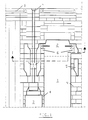
- the coking chamber is designated by (1). That at The raw gas from the coking gets into the above the coke bed arranged gas collecting space (2) and flows according to the invention according to Figures 1 and 2 by the arranged in the rotor wall (4) Passage opening (6) in the horizontal channel (5).
- the passage openings (6) are according to Figure 2 at one end of the heating wall. In the vicinity of these openings (6) is still the supply (9) of oxidizing agents, which are controlled from the outside will.
- the horizontal channel (5) is between the Runner wall (4) and the wall in which the inspection holes (7) are arranged are. On the side of the wall facing away from the rotor wall (4) with the The raw gas flows into inspection holes (7) in the horizontal channel (5) opposite direction and is via the trigger (10) from the coking system deducted.
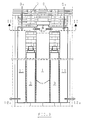
- the raw gas flows out of the gas collection space (2) through the openings (6a) to the vertical Channels (11) in which there is parallel after the supply of oxidizing agents (9a) flows down to the heating walls until it passes over the hood (10a) is withdrawn from the coking system.
Landscapes
- Chemical & Material Sciences (AREA)
- Engineering & Computer Science (AREA)
- Oil, Petroleum & Natural Gas (AREA)
- Materials Engineering (AREA)
- Organic Chemistry (AREA)
- Chemical Kinetics & Catalysis (AREA)
- General Chemical & Material Sciences (AREA)
- Production Of Liquid Hydrocarbon Mixture For Refining Petroleum (AREA)
- Carbon And Carbon Compounds (AREA)
Description
- Figur 1
- zeigt einen senkrechten Schnitt durch einen Teil der Verkokungskammer (1), der Ofendecke (8) und des Heizzuges (3) mit einem oberhalb der Heizwand angeordneten waagerechten Kanal (5).
- Figur 2
- zeigt einen waagerechten Schnitt nach der Linie I-I von Figur 1.
- Figur 3
- zeigt, ähnlich wie Figur 1, einen senkrechten Schnitt durch ein Ofensystem mit neben den Heizzügen (3) angeordneten senkrechten Kanälen (11).
- Figur 4
- zeigt einen waagerechten Schnitt nach der Linie II-II von Figur 3.
- (1)
- Verkokungskammer
- (2)
- Gassammelraum
- (3)
- Heizzug
- (4)
- Läuferwand
- (5)
- waagerechter Kanal
- (6), (6a)
- Durchtrittsöffnung für Rohgas
- (7)
- Schauloch
- (8)
- Ofendecke
- (9), (9a)
- Zufuhr von Oxidationsmittel
- (10), (10a)
- Abzug des behandelten Rohgases
- (11)
- senkrechter Kanal
Claims (9)
- Verfahren zur Hochtemperaturbehandlung von Verkokungsrohgas, wobei Einsatzkohle in einem Großraumverkokungsreaktor oder einer Vielkammerkoksofenbatterie verkokt und das dabei erhaltene Rohgas einer Hochtemperaturbehandlung unterzogen und das dabei anfallende Rohspaltgas als ökologische Energie das konventionelle Koksofengas ersetzen oder als Reduktionsgas einer Erzreduktion zugeführt wird, dadurch gekennzeichnet, daß, vorzugsweise nach Beendigung des Füllvorganges, die Hochtemperaturbehandlung, unabhängig von der Verbrennung des Heizgases in den Heizzügen, als integrierter Bestandteil des Verkokungsprozesses bei Temperaturen von über 800 °C, vorzugsweise 900 bis 1.300 °C, unter Zugabe einer bedarfsproportionalen Menge von Oxidationsmittel innerhalb des heißen Bereiches des Ofenblockes erfolgt, wobei das Oxidationsmittel direkt dem ungekühlten Rohgas zugegeben und das Rohspaltgas zur weiteren Verwendung aus dem Verkokungssystem abgezogen wird.
- Verfahren nach Anspruch 1, dadurch gekennzeichnet, daß das Oxidationsmittel in den Gassammelraum der Verkokungskammer durch die Füllöcher und/oder durch an den Ofenköpfen angeordnete Öffnungen zugegeben wird und daß das Rohspaltgas über die Steigerohre und/oder an sich bekannte Überleitrohre aus dem Gassammelraum abgezogen wird.
- Verfahren nach Anspruch 1 oder 2, dadurch gekennzeichnet, daß das Oxidationsmittel dem ungekühlten Rohgas am Fuß des Steigrohres oder in einer Gassammelleitung zugegeben wird.
- Verfahren nach Anspruch 1, dadurch gekennzeichnet, daß das Rohgas aus dem Gassammelraum der Verkokungskammer in oberhalb der Heizzüge oder oberhalb des Gassammelraumes angeordnete waagerechte Kanäle und/oder in auf der den Verkokungskammern abgewandten Seite der Kanäle und/oder in auf der den Verkokungskammern abgewandten Seite der Heizzüge angeordnete senkrechte Kanäle zur Hochtemperaturbehandlung geleitet wird.
- Verfahren nach den Ansprüchen 1 bis 4, dadurch gekennzeichnet, daß das Rohgas bei der Hochtemperaturbehandlung durch Schüttungen oder Packungen aus Keramik- und/oder Katalysatormaterial geleitet wird.
- Vorrichtung zur Durchführung des Verfahrens nach den vorhergehenden Ansprüchen mit horizontal angeordneten Verkokungskammern und seitlich daneben angeordneten aus senkrechten Heizzügen bestehenden Heizwänden zur indirekten Beheizung der Verkokungskammern sowie mit Einrichtungen zur Ableitung der Rohspaltgase aus dem Bereich des Ofenblokkes, vorzugsweise der Verkokungskammer, dadurch gekennzeichnet, daß oberhalb der Heizzüge (3), vorzugsweise auf der Höhe des Gassammelraumes (2), sich in Längsrichtung der Heizwand erstreckende waagerechte Kanäle (5) angeordnet sind, die keine Verbindung mit den Heizzügen (3) haben, über Durchtrittsöffnungen (6) für das Rohgas mit dem Gassammelraum (2) in Verbindung stehen und Anschlüsse zur Zufuhr von Oxidationsmittel (9) sowie zum Abzug des behandelten Rohgases (10) besitzen.
- Vorrichtung zur Durchführung des Verfahrens nach den vorhergehenden Ansprüchen mit horizontal angeordneten Verkokungskammern und seitlich daneben angeordneten aus senkrechten Heizzügen bestehenden Heizwänden zur indirekten Beheizung der Verkokungskammern sowie mit Einrichtungen zur Ableitung der Rohspaltgase aus dem Bereich des Ofenblokkes, vorzugsweise der Verkokungskammer, dadurch gekennzeichnet, daß auf der der Ofenkammer (1) abgekehrten Seite der Heizzüge (3) ein oder mehrere senkrechte Kanäle (11) zur Hochtemperaturbehandlung des Rohgases angeordnet sind, die keine Verbindung mit den Heizzügen (3) haben, an ihrem oberen Ende etwa auf der Höhe des Gassammelraumes (2) waagerecht mit dem Gassammelraum (2) in Verbindung stehende Durchtrittsöffnungen (6a) für das Rohgas sowie vorzugsweise am oberen Ende Anschlüsse für die Zufuhr von Oxidationsmittel (9a) und am unteren Ende Anschlüsse für den Abzug des behandelten Rohgases (10a) besitzen.
- Vorrichtung nach Anspruch 6 oder 7, dadurch gekennzeichnet, daß die Durchtrittsöffnungen (6, 6a) für das Rohgas im Bereich eines Kopfendes der Verkokungskammer (1) und die Zuführung für das Oxidationsmittel (9, 9a) in der Nähe dieser Durchtrittsöffnungen (6, 6a) angeordnet sind.
- Vorrichtung nach Anspruch 6, dadurch gekennzeichnet, daß der waagerechte Kanal (5) sich von einem Kopfende der Heizwand bis zum anderen Kopfende und zurück erstreckt, wobei Durchtrittsöffnung (6), Zufuhr für das Oxidationsmittel (9) und Abzug des behandelten Rohgases (10) sich an demselben Kopfende befinden.
Applications Claiming Priority (5)
| Application Number | Priority Date | Filing Date | Title |
|---|---|---|---|
| DE4401119 | 1994-01-18 | ||
| DE4401119 | 1994-01-18 | ||
| DE4421952A DE4421952C2 (de) | 1994-01-18 | 1994-06-23 | Verfahren und Vorrichtung zur Hochtemperaturbehandlung von Verkokungsrohgas |
| DE4421952 | 1994-06-23 | ||
| PCT/EP1995/000125 WO1995019405A1 (de) | 1994-01-18 | 1995-01-13 | Verfahren zur hochtemperaturbehandlung von verkokungsrohgas |
Publications (2)
| Publication Number | Publication Date |
|---|---|
| EP0740694A1 EP0740694A1 (de) | 1996-11-06 |
| EP0740694B1 true EP0740694B1 (de) | 1998-12-16 |
Family
ID=25933054
Family Applications (1)
| Application Number | Title | Priority Date | Filing Date |
|---|---|---|---|
| EP95906938A Expired - Lifetime EP0740694B1 (de) | 1994-01-18 | 1995-01-13 | Verfahren zur hochtemperaturbehandlung von verkokungsrohgas |
Country Status (4)
| Country | Link |
|---|---|
| EP (1) | EP0740694B1 (de) |
| AT (1) | ATE174614T1 (de) |
| AU (1) | AU1534095A (de) |
| WO (1) | WO1995019405A1 (de) |
Family Cites Families (6)
| Publication number | Priority date | Publication date | Assignee | Title |
|---|---|---|---|---|
| DE669850C (de) * | 1939-01-05 | Kohle Und Eisenforschung G M B | Waagerechter Kammerofen | |
| DE518921C (de) * | 1929-07-10 | 1931-02-21 | Stettiner Chamotte Fabrik Act | Einrichtung zum UEberhitzen von Destillationsgasen |
| US2116641A (en) * | 1935-01-29 | 1938-05-10 | Koppers Co Inc | Recovery of valuable by-products during the production of gas and coke |
| DE678425C (de) * | 1936-04-10 | 1939-07-15 | Koppers Gmbh Heinrich | Verfahren zur Verbesserung der Ausbeute an wertvollen Kohlenwasserstoffen bei der Verkokung bituminoeser Brennstoffe bei niedrigen Temperaturen |
| DE4210003A1 (de) * | 1992-03-27 | 1993-09-30 | Ruhrkohle Ag | Kombiniertes Verfahren zur Erzeugung von metallurgischem Koks und Eisenschwamm |
| DE4230028C1 (de) * | 1992-09-10 | 1993-11-11 | Still Otto Gmbh | Verkokungssystem und Verfahren zur Verkokung |
-
1995
- 1995-01-13 AU AU15340/95A patent/AU1534095A/en not_active Abandoned
- 1995-01-13 EP EP95906938A patent/EP0740694B1/de not_active Expired - Lifetime
- 1995-01-13 WO PCT/EP1995/000125 patent/WO1995019405A1/de not_active Ceased
- 1995-01-13 AT AT95906938T patent/ATE174614T1/de not_active IP Right Cessation
Also Published As
| Publication number | Publication date |
|---|---|
| EP0740694A1 (de) | 1996-11-06 |
| ATE174614T1 (de) | 1999-01-15 |
| AU1534095A (en) | 1995-08-01 |
| WO1995019405A1 (de) | 1995-07-20 |
Similar Documents
| Publication | Publication Date | Title |
|---|---|---|
| EP0671453B1 (de) | Verfahren zum Erzeugen von Holzkohle im Wanderbett | |
| DE102009053747B4 (de) | Verfahren zur Reduzierung von Stickoxiden aus dem Abgas eines Koksofens | |
| EP2714942B1 (de) | Reduktion von metalloxiden unter verwendung eines sowohl kohlenwasserstoff als auch wasserstoff enthaltenden gasstromes | |
| DE2952065A1 (de) | Verfahren zur trockenkuehlung von koks und kokskuehleinrichtung zur durchfuehrung des verfahrens | |
| EP4396382A1 (de) | Verfahren zur herstellung einer eisenschmelze | |
| WO2002000945A1 (de) | Verfahren und anlage zur gasreduktion von teilchenförmigen oxidhältigen erzen | |
| DE2825429C2 (de) | Verfahren zur Hochtemperaturbehandlung von durch Pyrolyse von Müll erhaltenen Schwelgasen | |
| DE2756330C2 (de) | Vertikalkammer-Verkokungsöfen in batterieweiser Anordnung zum kontinuierlichen Verkoken von Briketts aus Stein-, Braunkohle oder Torf | |
| DE3000808C2 (de) | Verfahren zur Nutzung der fühlbaren Kokswärme an einer Verkokungsanlage sowie Anlage zur Durchführung eines solchen Verfahrens | |
| DE3044989C2 (de) | Verfahren zur trockenen Kokskühlung | |
| DE2837416C3 (de) | Vorrichtung zur Weiterverarbeitung von Kohleentgasungsrohgas | |
| DE4421952C2 (de) | Verfahren und Vorrichtung zur Hochtemperaturbehandlung von Verkokungsrohgas | |
| DE2947128A1 (de) | Verfahren zur kontinuierlichen erzeugung eines hochtemperatur-reduktionsgases | |
| DE2710106A1 (de) | Verfahren zur erzeugung von fluessigem roheisen | |
| EP0740694A1 (de) | Verfahren zur hochtemperaturbehandlung von verkokungsrohgas | |
| DE869192C (de) | Verfahren zur Umsetzung von Kohlenwasserstoffe enthaltenden Gasen zu Wasserstoff und Kohlenoxyd | |
| DE2164008C3 (de) | Verfahren zur Herstellung von reduzierendem Gas | |
| AT206101B (de) | Verfahren zur thermischen oder thermisch/katalytischen Umwandlung organische Schwefelverbindungen enthaltender, flüssiger oder gasförmiger Kohlenwasserstoffe | |
| DE740734C (de) | Verfahren zur ununterbrochenen Erzeugung von Wassergas | |
| US2116641A (en) | Recovery of valuable by-products during the production of gas and coke | |
| DE897610C (de) | Verfahren zur Erzeugung von Gasen | |
| DE675399C (de) | Aussen beheizter senkrechter Kammerofen | |
| DE81916C (de) | ||
| DE2150682C2 (de) | Verfahren für den Betrieb eines Hochofens | |
| DE19936935C2 (de) | Verfahren und Vorrichtung zur Leistungssteigerung und Brennstoffeinsparung bei der Erzeugung von Roheisen |
Legal Events
| Date | Code | Title | Description |
|---|---|---|---|
| PUAI | Public reference made under article 153(3) epc to a published international application that has entered the european phase |
Free format text: ORIGINAL CODE: 0009012 |
|
| 17P | Request for examination filed |
Effective date: 19960809 |
|
| AK | Designated contracting states |
Kind code of ref document: A1 Designated state(s): AT BE DE ES FR GB |
|
| 17Q | First examination report despatched |
Effective date: 19971208 |
|
| GRAG | Despatch of communication of intention to grant |
Free format text: ORIGINAL CODE: EPIDOS AGRA |
|
| GRAG | Despatch of communication of intention to grant |
Free format text: ORIGINAL CODE: EPIDOS AGRA |
|
| GRAH | Despatch of communication of intention to grant a patent |
Free format text: ORIGINAL CODE: EPIDOS IGRA |
|
| GRAH | Despatch of communication of intention to grant a patent |
Free format text: ORIGINAL CODE: EPIDOS IGRA |
|
| GRAA | (expected) grant |
Free format text: ORIGINAL CODE: 0009210 |
|
| AK | Designated contracting states |
Kind code of ref document: B1 Designated state(s): AT BE DE ES FR GB |
|
| PG25 | Lapsed in a contracting state [announced via postgrant information from national office to epo] |
Ref country code: ES Free format text: THE PATENT HAS BEEN ANNULLED BY A DECISION OF A NATIONAL AUTHORITY Effective date: 19981216 |
|
| REF | Corresponds to: |
Ref document number: 174614 Country of ref document: AT Date of ref document: 19990115 Kind code of ref document: T |
|
| PG25 | Lapsed in a contracting state [announced via postgrant information from national office to epo] |
Ref country code: AT Free format text: LAPSE BECAUSE OF NON-PAYMENT OF DUE FEES Effective date: 19990113 |
|
| REF | Corresponds to: |
Ref document number: 59504556 Country of ref document: DE Date of ref document: 19990128 |
|
| ET | Fr: translation filed | ||
| GBT | Gb: translation of ep patent filed (gb section 77(6)(a)/1977) |
Effective date: 19990205 |
|
| PLBE | No opposition filed within time limit |
Free format text: ORIGINAL CODE: 0009261 |
|
| STAA | Information on the status of an ep patent application or granted ep patent |
Free format text: STATUS: NO OPPOSITION FILED WITHIN TIME LIMIT |
|
| 26N | No opposition filed | ||
| PGFP | Annual fee paid to national office [announced via postgrant information from national office to epo] |
Ref country code: GB Payment date: 20001212 Year of fee payment: 7 |
|
| PGFP | Annual fee paid to national office [announced via postgrant information from national office to epo] |
Ref country code: DE Payment date: 20010102 Year of fee payment: 7 |
|
| PGFP | Annual fee paid to national office [announced via postgrant information from national office to epo] |
Ref country code: FR Payment date: 20010103 Year of fee payment: 7 |
|
| PGFP | Annual fee paid to national office [announced via postgrant information from national office to epo] |
Ref country code: BE Payment date: 20010118 Year of fee payment: 7 |
|
| REG | Reference to a national code |
Ref country code: GB Ref legal event code: IF02 |
|
| PG25 | Lapsed in a contracting state [announced via postgrant information from national office to epo] |
Ref country code: GB Free format text: LAPSE BECAUSE OF NON-PAYMENT OF DUE FEES Effective date: 20020113 |
|
| PG25 | Lapsed in a contracting state [announced via postgrant information from national office to epo] |
Ref country code: BE Free format text: LAPSE BECAUSE OF NON-PAYMENT OF DUE FEES Effective date: 20020131 |
|
| BERE | Be: lapsed |
Owner name: THYSSEN STILL OTTO ANLAGENTECHNIK G.M.B.H. Effective date: 20020131 |
|
| PG25 | Lapsed in a contracting state [announced via postgrant information from national office to epo] |
Ref country code: DE Free format text: LAPSE BECAUSE OF NON-PAYMENT OF DUE FEES Effective date: 20020801 |
|
| GBPC | Gb: european patent ceased through non-payment of renewal fee |
Effective date: 20020113 |
|
| PG25 | Lapsed in a contracting state [announced via postgrant information from national office to epo] |
Ref country code: FR Free format text: LAPSE BECAUSE OF NON-PAYMENT OF DUE FEES Effective date: 20020930 |
|
| REG | Reference to a national code |
Ref country code: FR Ref legal event code: ST |