EP0735296B1 - Linearantrieb - Google Patents
Linearantrieb Download PDFInfo
- Publication number
- EP0735296B1 EP0735296B1 EP96100248A EP96100248A EP0735296B1 EP 0735296 B1 EP0735296 B1 EP 0735296B1 EP 96100248 A EP96100248 A EP 96100248A EP 96100248 A EP96100248 A EP 96100248A EP 0735296 B1 EP0735296 B1 EP 0735296B1
- Authority
- EP
- European Patent Office
- Prior art keywords
- linear drive
- drive according
- section
- lock elements
- traction mechanism
- Prior art date
- Legal status (The legal status is an assumption and is not a legal conclusion. Google has not performed a legal analysis and makes no representation as to the accuracy of the status listed.)
- Expired - Lifetime
Links
- 230000007246 mechanism Effects 0.000 claims description 14
- 210000002105 tongue Anatomy 0.000 claims description 10
- 230000008878 coupling Effects 0.000 claims description 7
- 238000010168 coupling process Methods 0.000 claims description 7
- 238000005859 coupling reaction Methods 0.000 claims description 7
- 230000000295 complement effect Effects 0.000 claims description 5
- 239000000853 adhesive Substances 0.000 claims description 3
- 230000001070 adhesive effect Effects 0.000 claims description 3
- 230000000712 assembly Effects 0.000 claims description 3
- 238000000429 assembly Methods 0.000 claims description 3
- 238000007789 sealing Methods 0.000 claims 11
- 238000006073 displacement reaction Methods 0.000 description 6
- 230000008901 benefit Effects 0.000 description 2
- 230000000873 masking effect Effects 0.000 description 2
- 239000000463 material Substances 0.000 description 2
- 238000000034 method Methods 0.000 description 2
- 230000036316 preload Effects 0.000 description 2
- 230000008569 process Effects 0.000 description 2
- 238000000926 separation method Methods 0.000 description 2
- 210000001520 comb Anatomy 0.000 description 1
- 238000010276 construction Methods 0.000 description 1
- 238000011109 contamination Methods 0.000 description 1
- 230000007547 defect Effects 0.000 description 1
- 238000001514 detection method Methods 0.000 description 1
- 238000011161 development Methods 0.000 description 1
- 230000018109 developmental process Effects 0.000 description 1
- 239000012530 fluid Substances 0.000 description 1
- 238000002347 injection Methods 0.000 description 1
- 239000007924 injection Substances 0.000 description 1
- 238000004519 manufacturing process Methods 0.000 description 1
- 230000009993 protective function Effects 0.000 description 1
- 230000007704 transition Effects 0.000 description 1
Images
Classifications
-
- F—MECHANICAL ENGINEERING; LIGHTING; HEATING; WEAPONS; BLASTING
- F16—ENGINEERING ELEMENTS AND UNITS; GENERAL MEASURES FOR PRODUCING AND MAINTAINING EFFECTIVE FUNCTIONING OF MACHINES OR INSTALLATIONS; THERMAL INSULATION IN GENERAL
- F16G—BELTS, CABLES, OR ROPES, PREDOMINANTLY USED FOR DRIVING PURPOSES; CHAINS; FITTINGS PREDOMINANTLY USED THEREFOR
- F16G3/00—Belt fastenings, e.g. for conveyor belts
-
- F—MECHANICAL ENGINEERING; LIGHTING; HEATING; WEAPONS; BLASTING
- F15—FLUID-PRESSURE ACTUATORS; HYDRAULICS OR PNEUMATICS IN GENERAL
- F15B—SYSTEMS ACTING BY MEANS OF FLUIDS IN GENERAL; FLUID-PRESSURE ACTUATORS, e.g. SERVOMOTORS; DETAILS OF FLUID-PRESSURE SYSTEMS, NOT OTHERWISE PROVIDED FOR
- F15B15/00—Fluid-actuated devices for displacing a member from one position to another; Gearing associated therewith
- F15B15/08—Characterised by the construction of the motor unit
- F15B15/084—Characterised by the construction of the motor unit the motor being of the rodless piston type, e.g. with cable, belt or chain
-
- F—MECHANICAL ENGINEERING; LIGHTING; HEATING; WEAPONS; BLASTING
- F16—ENGINEERING ELEMENTS AND UNITS; GENERAL MEASURES FOR PRODUCING AND MAINTAINING EFFECTIVE FUNCTIONING OF MACHINES OR INSTALLATIONS; THERMAL INSULATION IN GENERAL
- F16H—GEARING
- F16H19/00—Gearings comprising essentially only toothed gears or friction members and not capable of conveying indefinitely-continuing rotary motion
- F16H19/02—Gearings comprising essentially only toothed gears or friction members and not capable of conveying indefinitely-continuing rotary motion for interconverting rotary or oscillating motion and reciprocating motion
- F16H19/06—Gearings comprising essentially only toothed gears or friction members and not capable of conveying indefinitely-continuing rotary motion for interconverting rotary or oscillating motion and reciprocating motion comprising flexible members, e.g. an endless flexible member
- F16H19/0672—Gearings comprising essentially only toothed gears or friction members and not capable of conveying indefinitely-continuing rotary motion for interconverting rotary or oscillating motion and reciprocating motion comprising flexible members, e.g. an endless flexible member characterised by means for tensioning the flexible member
-
- F—MECHANICAL ENGINEERING; LIGHTING; HEATING; WEAPONS; BLASTING
- F16—ENGINEERING ELEMENTS AND UNITS; GENERAL MEASURES FOR PRODUCING AND MAINTAINING EFFECTIVE FUNCTIONING OF MACHINES OR INSTALLATIONS; THERMAL INSULATION IN GENERAL
- F16H—GEARING
- F16H19/00—Gearings comprising essentially only toothed gears or friction members and not capable of conveying indefinitely-continuing rotary motion
- F16H19/02—Gearings comprising essentially only toothed gears or friction members and not capable of conveying indefinitely-continuing rotary motion for interconverting rotary or oscillating motion and reciprocating motion
- F16H19/06—Gearings comprising essentially only toothed gears or friction members and not capable of conveying indefinitely-continuing rotary motion for interconverting rotary or oscillating motion and reciprocating motion comprising flexible members, e.g. an endless flexible member
- F16H2019/0681—Gearings comprising essentially only toothed gears or friction members and not capable of conveying indefinitely-continuing rotary motion for interconverting rotary or oscillating motion and reciprocating motion comprising flexible members, e.g. an endless flexible member the flexible member forming a closed loop
- F16H2019/0686—Gearings comprising essentially only toothed gears or friction members and not capable of conveying indefinitely-continuing rotary motion for interconverting rotary or oscillating motion and reciprocating motion comprising flexible members, e.g. an endless flexible member the flexible member forming a closed loop the flexible member being directly driven by a pulley or chain wheel
Definitions
- DE 40 16 867 A1 describes a linear drive that has a two toothed belts formed as gear wheels has, the ends of which are designed as screw connections Connection devices set on an output member that couple with a load to be transported leaves.
- the required preload of the acting as a traction device Timing belt is adjusted by the connection devices which is displaceable via the toothed belt engaged Have blocks that are relative with the help of screws to the output link.
- the adjustment of the tension means is in the known linear drive relatively cumbersome. It must be done with a Screwdriver handling between the belts of the timing belt will. Furthermore, the known configuration of a Hardly realize output element in very small linear drives, because you can quickly reach the limits of miniaturization.
- variable closed position is an advantage which specify the different tension means tensions Tolerance compensation enabled.
- the through the longitudinal guides with each other cooperating lock elements can be pushed together as far until the desired preload value is reached is then to the closed position set in this way by suitable, between the overlapping parts the fastening sections effective fastening measures fix. Since the fixing area is outside the longitudinal recess can be located, it is very accessible, so that the turnbuckle is easy to handle.
- the construction of the output link enables this to be achieved small sizes, what the miniaturization of linear drives facilitated.
- the longitudinal guides of easily producible interlocking are preferred Tongue and groove arrangements formed.
- the closing process of the turnbuckle is facilitated if the Lock elements at least during the end region of the displacement path are supported against each other in all transverse directions. In this case, it is sufficient to use a suitable lock element To apply pressure force, the need for a lateral There is no support due to the integrated cross support.
- the lock elements For mutual attachment of the lock elements is, for example a screw or pin connection is provided, the has at least one bolt-like cross member that simultaneously in both overlapping parts of the closure sections intervenes and in particular enforces this.
- the for Receptions of the cross member serving recesses are expedient only then introduced into the closure sections, when the desired closed position is reached.
- the one that interacts with the housing of the linear drive during operation Guide section of the output member is expedient of guide pistons provided on the two lock elements formed over narrower guide bars with the closure sections are connected.
- the two lock elements are preferably of identical design, expediently each in one piece, made of plastic material existing components.
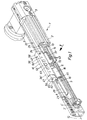
- FIG. 1 and 2 show an electric motor operated linear drive 1 out. It has a profiled elongated Housing 2, the two end faces each with a cover 3, 3 'is provided. In each cover there is one of a deflecting element 4, 4 'formed in a rotatably mounted gear wheel arranged. One deflection element 4 'is freely rotatable. The other deflection element 4 is in drive connection with an electric motor 5, which in particular laterally on the assigned End cover 3 is flanged.
- the two deflection elements 4, 4 ' is a strand-like traction device 6 looped around. It is compliant and transverse executed in the embodiment as a toothed belt with the combs two deflection elements 4, 4 '. Instead, for example also a link strand, for example a chain, be provided, or another band-like element.
- the traction means 6 has two dreams 7, 8, which are parallel extend to each other and both in the longitudinal direction 12 of the housing 2 are aligned.
- the first, located at the bottom in FIG. 2 Run 7 is continuous and runs in a longitudinal direction 12 extending groove-like recess 13 of the housing 2. It is thereby sunk in the housing 2.
- the longitudinal opening the recess 13 can be covered by a strip-like cover 14 be closed.
- the second run 8 of the traction means 6 is interrupted. Which resulting in two traction ends 15, 15 ' but attached to an intermediate output member 16, so that overall there is a closed loop around the deflecting elements 4, 4 'results.
- the output member 16 has a side next to the housing 2 arranged outside this coupling section 17, the for coupling with a load to be moved.
- This not closer Load shown can be directly or with interposition of suitable connecting elements on the coupling section 17 be determined.
- the load to be moved on a guide carriage, not shown, are attached, which is connected to the coupling section 17 and on supports an external longitudinal guide.
- the traction means 6 with the help of the electric motor 5 driven to a circular movement, from the a linear movement of the output member 16 in two possible directions of movement results in the direction of the longitudinal axis 12. Corresponding moves the coupled to the output member 16 Load.
- the Driving force from one through fluid to movement driven piston delivered in the first strand 7 can be interposed.
- the output member 16 runs with a guide section 18 in a lengthwise direction to the outer surface of the housing 22 open longitudinal recess 23 of the housing 2.
- the second run 8 of the traction means 6 runs inside it Longitudinal recess 23 parallel to this.
- the traction ends 15 are set on the leadership part 18.
- the longitudinal depression 23 has a reference to FIG Housing outer surface 22 lower lying, enlarged in cross section Section 24, which contours preferably circular is. It is cylindrical, for example.
- the connection to the housing outer surface 22 is also in the longitudinal direction 12 extending slit-like narrow section 25 forth. This is covered from the outside by a masking tape 26, the one Prevents contamination from entering and ends at the two end caps 3, 3 'is fixed.
- the output link 16 contains an axially continuous opening 27, which of the Cover tape 26 is penetrated and one shown in Figure 3 Has curve shape that causes the masking tape 26th in the linear movement of the output member 16 in its area is lifted locally from the slot-like section 25.
- the output member 16 is not only used to deliver power to the outside, but also forms a turnbuckle for the traction mechanism 6.
- the output member 16 is during assembly of the traction device 6 for closing the traction device in the area of the traction device ends 15, 15 'used.
- the output member settles or turnbuckle 16 from two lock elements 28, 28 ' together, which are in the open position shown separate components.
- One of the traction ends is located on each of the two lock elements 28, 28 ' 15, 15 'in particular releasably attached. With this connecting devices 32 used is preferred There are no screw connections that prevent miniaturization can.
- Each lock element 28, 28 ' has a guide section 33, with which it is longitudinally movable within the longitudinal recess 23 is recorded.
- this consists of an in the extended section 24 running guide piston 34 and one radially outward on these subsequent narrower Guide web 35 together.
- the guide web 35 penetrates the slit-like section 25 the longitudinal recess 23 lying closure portion 36, 36 '.
- the traction ends 15, 15 ' are each via a connecting device 32 firmly connected to the one guide piston 34.
- the connection device 32 according to the example has a in the plane of the traction device 6 slot-like recess 37 on one long side (at 44) and to the rear End face 38 of the guide piston 34 is open.
- the recess 37 carries a linear toothing 43, which is used for toothing of the traction means 6 is complementary.
- the height of the recess 37 corresponds approximately to the thickness of the traction means 6, which over the lying on the lateral surface of the guide piston 34 longitudinal Opening 44 is pressed sideways into the recess 37.
- the traction means 6 comes with its entire width within the Guide piston 34 to lie and protrudes on the rear end face 38 with its section leading to the first run 7. In this way, the relevant traction means end 15, 15 ' positively and non-positively on the relevant lock element 28, 28 ' fixed.
- a securing ring can be used to secure the connection 45 placed on a front collar of the guide piston 34 be the piston sections separated from the recess 37 holds together and also encloses the traction means 6. Consequently is a very simple, screwless connection device 32 before, which are also extremely small Output elements 16 can be used.
- the arrangement according to the example is such that the Do not overlap guide sections 33 in the closed position.
- the two guide pistons 34 and the two guide webs 35 are axially aligned with each other, whereby they already mentioned guide section 18, which only by a separation point 48 is axially divided, which is a space 47 can have.
- the closure sections 36, 36 ' are designed so that they in the closed position laterally in the direction of displacement 46 overlapping longitudinal direction 12 overlap.
- the one running in the longitudinal direction 12 Parting plane 52 between the overlap portions 53 runs parallel to the circumferential plane of the traction means 6 and preferably in the center.
- the front end face 54 of a respective overlap section 52 lies opposite a boundary surface 55 which is on a from the rear end region of the other closure section 36, 36 'formed, preferably as a stop section acting lot 56 is provided.
- Between the cross Surfaces 54, 55 extending in the longitudinal direction 12 can be the mentioned gaps 47 are located, although said must be that the two lock elements 28, 28 'with appropriate Closed position in the area of the gaps 47 also in can be in direct contact with each other.
- each closure section 36, 36 ' according to the example has about an L-like shape, with the longer L-leg the in the longitudinal direction 12 aligned overlap portion 53 and shorter L-legs the transverse stop 56 forms.
- the lock elements 28, 28 ' are interacting Longitudinal guides 57, 57 'coupled to one another in a longitudinally displaceable manner.
- the embodiment has two pairs of positively interacting Longitudinal guides 57, 57 ', preferably as a groove and spring assemblies 58 are formed. Every overlap lot 53 has a long side at the bottom of the front portion 49 inward guide groove 59, in the one on the other Lock element in the transition area between the guide section 33 and the closure section 36, 36 'arranged guide rib 60 engages.
- Stop section 56 can also help prevent overstretching to prevent during the clamping process.
- this protective function can also from the facing front faces 54 of the guide sections 33 are adopted, in which case the stop part 56 can only serve the purpose of a locking recess 63 for the tongues 62 and the generated thereby To provide transverse locking of the two lock elements 28, 28 '.
- pin connection 66 instead of a pin connection 66, for example, it would also be one Screw or rivet connection conceivable, with a releasable connection has the advantage that the traction means 6 in the event of a defect can be easily replaced.
- the fastening measure is between the two lock elements 28, 28 ' an adhesive connection or a welded connection, preferably an ultrasonic welded connection is provided.
- the connecting surfaces are expediently the one in the other Parting plane 52 facing side surfaces of the overlapping parts 53.
- the separation points between the two lock elements are preferred 28, 28 'placed so that for the 26 through opening 27 over its entire length Longitudinal division results, which leads to the opening 27 in the open position of the turnbuckle is open lengthways.
- Both Lock elements 28, 28 ' have boundary surfaces 69, 69', which with assembled lock elements 28, 28 'to the inner surface complete the opening 27. Runs according to the example the opening 27 in the region of the two closure sections 36, 36 ', the overlap portions 53 of the side surfaces of the Form opening 27.
- the base area 73 of the opening is preferably predetermined on the guide section 33.
- the coupling section 17 has a plurality of transverse bores 70, which are used to attach one to be transported Allow load. For the same reason it is pen-shaped Cross member 67 sleeve-shaped.
- At least one of the guide pistons 34 can have a recess 71 have, in which a magnetic part 72 is mounted, which to a Position detection device of the linear drive 1 belongs.
Landscapes
- Engineering & Computer Science (AREA)
- General Engineering & Computer Science (AREA)
- Mechanical Engineering (AREA)
- Physics & Mathematics (AREA)
- Fluid Mechanics (AREA)
- Transmission Devices (AREA)
- Devices For Conveying Motion By Means Of Endless Flexible Members (AREA)
- Manipulator (AREA)
- Control Of Stepping Motors (AREA)
- Amplifiers (AREA)
- Control Of Motors That Do Not Use Commutators (AREA)
Description
- das zwischen zwei Zugmittelenden (15, 15') des um Umlenkelemente (4,4') laufenden Zugmittels (6) angeordnet ist, und
- das im Betrieb eine durch das Zugmittel (6) veranlaßte Linearbewegung in Längsrichtung (12) eines Gehäuses (2) des Linearantriebes (1) ausführt,
- wobei die beiden Zugmittelenden (15, 15') jeweils über eine Verbindungseinrichtung (32) an dem Abtriebsglied (16) befestigt sind.
- das Abtriebsglied (16) ist als Spannschloß für das Zugmittel (6) ausgebildet, wobei das Spannschloß in zwei Schloßelemente (28, 28') unterteilt ist, die jeweils einem Zugmittelende (15, 15') zugeordnet sind und die in einer einer gewünschten Zugmittelspannung entsprechenden Schließstellung fest aneinander fixierbar sind,
- jedes Schloßelement weist einen innerhalb einer längsseits
offenen Längsvertiefung (23) des Gehäuses (2) laufenden
Führungsabschnitt (33) und einen außerhalb der Längsvertiefung
(23) angeordneten Verschlußabschnitt (36, 36')
auf, wobei
- der jeweilige Führungsabschnitt über die jeweilige Verbindungseinrichtung (32) mit dem jeweiligen Zugmittelende verbunden ist, und
- sich die Schloßelemente wenigstens mit ihren Verschlußabschnitten seitlich in Längsrichtung (12) überlappen,
- die Schloßelemente sind zur stufenlosen Einstellung der Zugmittelspannung über Längsführungen (57, 57', 61, 61') längsverschieblich miteinander gekoppelt, und
- die Schloßelemente sind zum Fixieren der Schließstellung an den sich überlappenden Partien (53) der Verschlußabschnitte aneinander festlegbar.
- Figur 1
- eine erste Bauform des erfindungsgemäßen Abtriebsgliedes im Zusammenhang mit einem damit ausgestatteten Linearantrieb, teilweise aufgebrochen,
- Figur 2
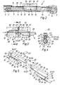
- einen Längsschnitt durch die in Figur 1 gezeigte Anordnung mit Blickrichtung gemäß Pfeil II aus Figur 1,
- Figur 3
- eine Einzeldarstellung des Abtriebsgliedes gemäß Figuren 1 und 2 in Seitenansicht, wobei der Verschlußabschnitt des rechten Schloßelementes abgebrochen dargestellt ist, so daß teilweise der Blick auf die Überlappungspartie des linken Schloßelementes freigegeben ist,
- Figur 4
- einen Querschnitt durch das Abtriebsglied der Figur 3 gemäß Schnittlinie IV-IV, und
- Figur 5
- das Abtriebsglied in Einzeldarstellung bei noch getrennten Schloßelementen in der Offenstellung im Zustand vor dem Schließen des als Spannschloß fungierenden Abtriebsgliedes.
Claims (19)
- Linearantrieb mit einem angetriebenen Zugmittel (6), beispielsweise ein Zahnriemen, und einem Abtriebsglied (16),das zwischen zwei Zugmittelenden (15,15') des um Umlenkelemente (4,4') laufenden Zugmittels (6) angeordnet ist, unddas im Betrieb eine durch das Zugmittel (6) veranlaßte Linearbewegung in Längsrichtung (12) eines Gehäuses (2) des Linearantriebes (1) ausführt,wobei die beiden Zugmittelenden (15,15') jeweils über eine Verbindungseinrichtung (32) an dem Abtriebsglied (16) befestigt sind, gekennzeichnet durch folgende Merkmale:das Abtriebsglied (16) ist als Spannschloß für das Zugmittel (6) ausgebildet, wobei das Spannschloß in zwei Schloßelemente (28, 28') unterteilt ist, die jeweils einem Zugmittelende (15, 15') zugeordnet sind und die in einer einer gewünschten Zugmittelspannung entsprechenden Schließstellung fest aneinander fixierbar sind,jedes Schloßelement weist einen innerhalb einer längsseits offenen Längsvertiefung (23) des Gehäuses (2) laufenden Führungsabschnitt (33) und einen außerhalb der Längsvertiefung (23) angeordneten Verschlußabschnitt (36, 36') auf, wobeider jeweilige Führungsabschnitt über die jeweilige Verbindungseinrichtung (32) mit dem jeweiligen Zugmittelende verbunden ist, undsich die Schloßelemente wenigstens mit ihren Verschlußabschnitten seitlich in Längsrichtung (12) überlappen,die Schloßelemente sind zur stufenlosen Einstellung der Zugmittelspannung über Längsführungen (57, 57', 61, 61') längsverschieblich miteinander gekoppelt, unddie Schloßelemente sind zum Fixieren der Schließstellung an den sich überlappenden Partien (53) der Verschlußabschnitte aneinander festlegbar.
- Linearantrieb nach Anspruch 1, dadurch gekennzeichnet, daß die Längsführungen (57, 57') zumindest teilweise von ineinandergreifenden Nut und Feder-Anordnungen (58) gebildet sind.
- Linearantrieb nach Anspruch 1 oder 2, dadurch gekennzeichnet, daß die Schloßelemente (28, 28'), insbesondere über die miteinander kooperierenden Längsführungen (61, 61'), zumindest während des Endbereiches des Verschiebeweges in allen Querrichtungen gegeneinander abgestützt sind.
- Linearantrieb nach Anspruch 3, dadurch gekennzeichnet, daß zur Querabstützung an wenigstens einem Schloßelement (28, 28') eine Zunge (62) vorgesehen ist, die in eine am anderen Schloßelement (28', 28) im Verschiebeweg der Zunge (62) angeordnete Ausnehmung (63) eingreifen kann.
- Linearantrieb nach Anspruch 4, dadurch gekennzeichnet, daß beide Schloßelemente (28, 28') mit einer Zunge (62) und, axial beabstandet zu dieser, mit einer Ausnehmung (63) versehen sind, wobei zum Zwecke des Spannens des Zugmittels (6) die Zungen (62) und Ausnehmungen (63) beim Zusammenschieben der Schloßelemente paarweise ineinandergreifen.
- Linearantrieb nach Anspruch 5, dadurch gekennzeichnet, daß die Zunge (62) an der vorderen Stirnseite (54) des jeweils einen Verschlußabschnittes (36, 36') und die zugeordnete Ausnehmung (63) an einer dieser Stirnseite (54) in Verschieberichtung (46) gegenüberliegenden Partie (56) des anderen Verschlußabschnittes angeordnet ist.
- Linearantrieb nach einem der Ansprüche 1 bis 6, dadurch gekennzeichnet, daß die überlappenden Partien (53) der Verschlußabschnitte (36, 36') leistenförmig ausgebildet sind.
- Linearantrieb nach einem der Ansprüche 1 bis 7, dadurch gekennzeichnet, daß zur gegenseitigen Festlegung der Schloßelemente (28, 28') in der Schließstellung eine zwischen den Verschlußabschnitten (36, 36') wirkende Schraub- oder Stiftverbindung (66) mit wenigstens einem in beide sich überlappenden Partien (53) eingreifenden Querglied (67) vorgesehen ist.
- Linearantrieb nach einem der Ansprüche 1 bis 8, dadurch gekennzeichnet, daß zur gegenseitigen Festlegung der Schloßelemente (28, 28') in der Schließstellung eine zwischen den Verschlußabschnitten (36, 36') wirkende Klebe- oder Schweißverbindung, z.B. eine Ultraschallschweißverbindung, vorgesehen ist.
- Linearantrieb nach einem der Ansprüche 1 bis 9, dadurch gekennzeichnet, daß die beiden zusammengefügten Verschlußabschnitte (36, 36') gemeinsam den mit einer zu transportierenden Last koppelbaren Kopplungsabschnitt (17) des Abtriebsgliedes (16) bilden.
- Linearantrieb nach einem der Ansprüche 1 bis 10, dadurch gekennzeichnet, daß jeder Führungsabschnitt (33) über einen in einem komplementären erweiterten Abschnitt (24) der Längsvertiefung (23) laufenden Führungskolben (34) verfügt, an dem das zugeordnete Zugmittelende (15, 15') über die Verbindungseinrichtung (32) festgelegt ist.
- Linearantrieb nach Anspruch 11, dadurch gekennzeichnet, daß jeder Führungsabschnitt (33) über einen Führungssteg (35) verfügt, der einen sich radial an den erweiterten Abschnitt (24) der Längsvertiefung (23) anschließenden schlitzartigen engeren Abschnitt (25) der Längsvertiefung (23) durchsetzt und den Führungskolben (34) mit dem zugeordneten Verschlußabschnitt (36, 36') verbindet.
- Linearantrieb nach Anspruch 11 oder 12, dadurch gekennzeichnet, daß die Führungskolben (34) der beiden Schloßelemente (28, 28') ohne gegenseitige Überlappung fluchtend axial aufeinanderfolgend angeordnet sind.
- Linearantrieb nach einem der Ansprüche 11 bis 13, dadurch gekennzeichnet, daß der Verschlußabschnitt (36, 36') eines jeweiligen Schloßelementes (28, 28') über die Vorderseite des zugeordneten Führungskolbens (34) hinausragt.
- Linearantrieb nach einem der Ansprüche 1 bis 14, dadurch gekennzeichnet, daß das Abtriebsglied in Längsrichtung (12) von einer Durchbrechung (27) durchsetzt ist, die ihrerseits von einem die Längsvertiefung (23) abdeckenden Abdeckband (26) durchsetzbar ist und die durch den Trennbereich (52) der beiden Schloßelemente (28, 28') über ihre gesamte Länge derart längsgeteilt ist, daß die Durchbrechung im getrennten Zustand der Schloßelemente (28, 28') längsseits zugänglich ist.
- Linearantrieb nach einem der Ansprüche 1 bis 15, dadurch gekennzeichnet, daß die Verbindungseinrichtungen (32) von die Zugmittelenden (15, 15') aufnehmenden innenverzahnten Aussparungen (37) gebildet sind.
- Linearantrieb nach einem der Ansprüche 1 bis 16, dadurch gekennzeichnet, daß die beiden Schloßelemente (28, 28') identisch ausgebildet sind.
- Linearantrieb nach einem der Ansprüche 1 bis 17, dadurch gekennzeichnet, daß der Linearantrieb (1) elektromotorisch betrieben ist, bei dem wenigstens eines der Umlenkelemente (4) als motorisch drehangetriebenes Rad ausgebildet ist.
- Linearantrieb nach einem der Ansprüche 1 bis 18, dadurch gekennzeichnet, daß die beiden Schloßelemente (28, 28') jeweils als einstückige Bauteile, insbesondere aus Kunststoffmaterial bestehend, ausgeführt sind.
Applications Claiming Priority (2)
| Application Number | Priority Date | Filing Date | Title |
|---|---|---|---|
| DE29505345U | 1995-03-31 | ||
| DE29505345U DE29505345U1 (de) | 1995-03-31 | 1995-03-31 | Abtriebsglied eines Linearantriebes |
Publications (2)
| Publication Number | Publication Date |
|---|---|
| EP0735296A1 EP0735296A1 (de) | 1996-10-02 |
| EP0735296B1 true EP0735296B1 (de) | 1998-06-10 |
Family
ID=8006075
Family Applications (1)
| Application Number | Title | Priority Date | Filing Date |
|---|---|---|---|
| EP96100248A Expired - Lifetime EP0735296B1 (de) | 1995-03-31 | 1996-01-10 | Linearantrieb |
Country Status (5)
| Country | Link |
|---|---|
| EP (1) | EP0735296B1 (de) |
| JP (1) | JP3217261B2 (de) |
| CA (1) | CA2167889C (de) |
| CZ (1) | CZ290624B6 (de) |
| DE (2) | DE29505345U1 (de) |
Cited By (2)
| Publication number | Priority date | Publication date | Assignee | Title |
|---|---|---|---|---|
| WO2009049379A1 (en) * | 2007-10-19 | 2009-04-23 | Automatic Technology (Australia) Pty Ltd | Improvements relating to drive assemblies |
| EP2110201A1 (de) * | 2008-04-15 | 2009-10-21 | Festo AG & Co. KG | Elektrischer Linearantrieb |
Families Citing this family (12)
| Publication number | Priority date | Publication date | Assignee | Title |
|---|---|---|---|---|
| DE29505345U1 (de) * | 1995-03-31 | 1995-05-18 | Festo Kg, 73734 Esslingen | Abtriebsglied eines Linearantriebes |
| DE19534932A1 (de) * | 1995-09-20 | 1997-03-27 | Marantec Antrieb Steuerung | Verbindungsvorrichtung für profilbehaftete Antriebsmittel |
| DE19636272A1 (de) * | 1996-09-06 | 1998-03-12 | Star Gmbh | Linearführungseinrichtung |
| WO1998013625A1 (de) * | 1996-09-26 | 1998-04-02 | Hörmann KG Antriebstechnik | Kupplung für zahngurte |
| DE29720518U1 (de) * | 1997-11-19 | 1998-02-05 | ERO-Führungen GmbH Erich Rothweiler & Söhne, 79843 Löffingen | Lineareinheit mit motorischem Stellantrieb |
| DE20002865U1 (de) | 1999-04-26 | 2000-05-18 | Rexroth Star GmbH, 97424 Schweinfurt | Lineareinheit |
| AT502967B1 (de) * | 2003-12-16 | 2009-03-15 | Thurnher Julius | Schiebeflügel-antriebseinrichtung |
| DE102004018012B4 (de) * | 2004-04-14 | 2007-01-11 | Müller, Michael, Dipl.-Ing. | Fördervorrichtung |
| DE202007004694U1 (de) * | 2007-03-30 | 2008-08-14 | Robert Bosch Gmbh | Lineareinheit |
| JP5135069B2 (ja) | 2008-06-12 | 2013-01-30 | 三鷹光器株式会社 | 医療用器具保持アーム装置 |
| CN114673438A (zh) * | 2020-12-24 | 2022-06-28 | 沈阳新松机器人自动化股份有限公司 | 一种独立式穿越防火门轨道系统及防火门系统 |
| DE102023122569B4 (de) * | 2023-08-23 | 2025-06-18 | Festo Se & Co. Kg | Zahnriemenachse mit einer Klemmvorrichtung |
Family Cites Families (9)
| Publication number | Priority date | Publication date | Assignee | Title |
|---|---|---|---|---|
| DE2047092B1 (de) * | 1970-09-24 | 1971-12-23 | Aristo Werke Dennert & Pape Kg | Bandantrieb |
| DE3016696C2 (de) * | 1980-04-30 | 1986-09-04 | Robert Bosch Gmbh, 7000 Stuttgart | Bandzylinder mit einem durch ein Fluid angetriebenen Kolben |
| DE3317113A1 (de) * | 1983-05-10 | 1984-11-15 | Knorr-Bremse GmbH, 8000 München | Positioniereinrichtung fuer kolbenstangenlose zylinder |
| DE8806099U1 (de) * | 1988-05-07 | 1988-07-21 | IEF-WERNER GmbH, 7743 Furtwangen | Linearantrieb |
| DD280490A1 (de) * | 1989-03-16 | 1990-07-11 | Umform & Plastverarb Fz | Antriebsvorrichtung zur bewegung eines schlittens von nc-gesteuerten maschinen und baugruppen |
| DE3914889A1 (de) | 1989-05-05 | 1990-11-08 | Knorr Bremse Ag | Kolbenstangenloser arbeitszylinder |
| GB2233711A (en) * | 1989-05-25 | 1991-01-16 | Clarke Douglas C | Rodless piston/cylinder unit |
| US5213182A (en) * | 1991-11-19 | 1993-05-25 | Otis Elevator Company | Elevator door operator cog belt linkage |
| DE29505345U1 (de) * | 1995-03-31 | 1995-05-18 | Festo Kg, 73734 Esslingen | Abtriebsglied eines Linearantriebes |
-
1995
- 1995-03-31 DE DE29505345U patent/DE29505345U1/de not_active Expired - Lifetime
-
1996
- 1996-01-10 EP EP96100248A patent/EP0735296B1/de not_active Expired - Lifetime
- 1996-01-10 DE DE59600257T patent/DE59600257D1/de not_active Expired - Fee Related
- 1996-01-23 CA CA002167889A patent/CA2167889C/en not_active Expired - Fee Related
- 1996-03-15 CZ CZ1996801A patent/CZ290624B6/cs not_active IP Right Cessation
- 1996-03-18 JP JP06143696A patent/JP3217261B2/ja not_active Expired - Fee Related
Cited By (3)
| Publication number | Priority date | Publication date | Assignee | Title |
|---|---|---|---|---|
| WO2009049379A1 (en) * | 2007-10-19 | 2009-04-23 | Automatic Technology (Australia) Pty Ltd | Improvements relating to drive assemblies |
| US8578653B2 (en) | 2007-10-19 | 2013-11-12 | Automatic Technology (Australia) Pty Ltd | Drive assemblies |
| EP2110201A1 (de) * | 2008-04-15 | 2009-10-21 | Festo AG & Co. KG | Elektrischer Linearantrieb |
Also Published As
| Publication number | Publication date |
|---|---|
| JP3217261B2 (ja) | 2001-10-09 |
| DE59600257D1 (de) | 1998-07-16 |
| CZ290624B6 (cs) | 2002-09-11 |
| CA2167889A1 (en) | 1996-10-01 |
| CZ80196A3 (en) | 1996-11-13 |
| JPH08291851A (ja) | 1996-11-05 |
| CA2167889C (en) | 2000-02-22 |
| EP0735296A1 (de) | 1996-10-02 |
| DE29505345U1 (de) | 1995-05-18 |
Similar Documents
| Publication | Publication Date | Title |
|---|---|---|
| EP1925866B1 (de) | Schelle aus Kunststoff | |
| EP0165497A2 (de) | Getriebe zur Überführung einer rotatorischen in eine translatorische Bewegung | |
| EP0735296A1 (de) | Abtriebsglied eines Linearantriebes | |
| EP3297799B1 (de) | Werkzeugmaschinentrennvorrichtung | |
| EP3044475B1 (de) | Synchronriemen mit riemenschloss | |
| DE102012004855A1 (de) | Schlupfverhinderungsmechanismus für einen Antriebskrafttransmissionsriemen | |
| DE3436075C1 (de) | Vorrichtung zur Ioesbaren Verbindung von Greiferschienenteilen der Greiferschienen in einer Transfer-Presse | |
| EP2110579B1 (de) | Elektrischer Linearantrieb | |
| DE19725642A1 (de) | Verfahren zur Herstellung eines Verbundes aus zwei Kunststoffteilen | |
| EP0918174A2 (de) | Lineareinheit mit motorischem Stellantrieb | |
| EP2121414B1 (de) | Elektrische servolenkung mit riemenantrieb | |
| DE4445132C1 (de) | Führungseinrichtung | |
| DE69030328T2 (de) | Haltevorrichtung für kolbenpositionsdetektor | |
| DE102007031337A1 (de) | Motorsäge und Klemmelement | |
| EP2754803B1 (de) | Riegelstangenbeschlag für ein Fenster oder eine Tür und Riegelstange für einen solchen Riegelstangenbeschlag | |
| DE2657905A1 (de) | Verbindung zwischen den kettengliedern einer gleiskette | |
| DE29917214U1 (de) | Vorrichtung zum Ausrichten von zwei benachbarten, nacheinander an einem Fahrzeug zu befestigenden Teilen | |
| EP1724495B1 (de) | Zahnriementrieb und Verfahren zur Herstellung einer Riemenscheibe für einen Zahnriementrieb | |
| DE20207715U1 (de) | Teleskopleiter | |
| DE3441100C2 (de) | ||
| DE2509518A1 (de) | Fuehrungsschienen-arretierung an motorisch angetriebenen handsaegen, insbesondere motorkettensaegen | |
| DE29705941U1 (de) | Verbindungselement für profilbehaftete Riemenenden | |
| EP0690237B1 (de) | Linearantrieb | |
| DE102007018924B4 (de) | Linearachse | |
| DE102020118163A1 (de) | Befestigungsmittel für Bandkanal einer Umreifungsmaschine |
Legal Events
| Date | Code | Title | Description |
|---|---|---|---|
| PUAI | Public reference made under article 153(3) epc to a published international application that has entered the european phase |
Free format text: ORIGINAL CODE: 0009012 |
|
| 17P | Request for examination filed |
Effective date: 19960801 |
|
| AK | Designated contracting states |
Kind code of ref document: A1 Designated state(s): CH DE FR LI SE |
|
| 17Q | First examination report despatched |
Effective date: 19970609 |
|
| GRAG | Despatch of communication of intention to grant |
Free format text: ORIGINAL CODE: EPIDOS AGRA |
|
| RAP1 | Party data changed (applicant data changed or rights of an application transferred) |
Owner name: FESTO AG & CO |
|
| GRAG | Despatch of communication of intention to grant |
Free format text: ORIGINAL CODE: EPIDOS AGRA |
|
| GRAH | Despatch of communication of intention to grant a patent |
Free format text: ORIGINAL CODE: EPIDOS IGRA |
|
| GRAH | Despatch of communication of intention to grant a patent |
Free format text: ORIGINAL CODE: EPIDOS IGRA |
|
| GRAA | (expected) grant |
Free format text: ORIGINAL CODE: 0009210 |
|
| AK | Designated contracting states |
Kind code of ref document: B1 Designated state(s): CH DE FR LI SE |
|
| REG | Reference to a national code |
Ref country code: CH Ref legal event code: NV Representative=s name: TROESCH SCHEIDEGGER WERNER AG Ref country code: CH Ref legal event code: EP |
|
| REF | Corresponds to: |
Ref document number: 59600257 Country of ref document: DE Date of ref document: 19980716 |
|
| ET | Fr: translation filed | ||
| PLBE | No opposition filed within time limit |
Free format text: ORIGINAL CODE: 0009261 |
|
| STAA | Information on the status of an ep patent application or granted ep patent |
Free format text: STATUS: NO OPPOSITION FILED WITHIN TIME LIMIT |
|
| 26N | No opposition filed | ||
| PGFP | Annual fee paid to national office [announced via postgrant information from national office to epo] |
Ref country code: SE Payment date: 20070117 Year of fee payment: 12 |
|
| EUG | Se: european patent has lapsed | ||
| PG25 | Lapsed in a contracting state [announced via postgrant information from national office to epo] |
Ref country code: SE Free format text: LAPSE BECAUSE OF NON-PAYMENT OF DUE FEES Effective date: 20080111 |
|
| PGFP | Annual fee paid to national office [announced via postgrant information from national office to epo] |
Ref country code: DE Payment date: 20090206 Year of fee payment: 14 |
|
| PGFP | Annual fee paid to national office [announced via postgrant information from national office to epo] |
Ref country code: CH Payment date: 20090327 Year of fee payment: 14 |
|
| PGFP | Annual fee paid to national office [announced via postgrant information from national office to epo] |
Ref country code: FR Payment date: 20090120 Year of fee payment: 14 |
|
| REG | Reference to a national code |
Ref country code: CH Ref legal event code: PL |
|
| REG | Reference to a national code |
Ref country code: FR Ref legal event code: ST Effective date: 20100930 |
|
| PG25 | Lapsed in a contracting state [announced via postgrant information from national office to epo] |
Ref country code: LI Free format text: LAPSE BECAUSE OF NON-PAYMENT OF DUE FEES Effective date: 20100131 Ref country code: FR Free format text: LAPSE BECAUSE OF NON-PAYMENT OF DUE FEES Effective date: 20100201 Ref country code: CH Free format text: LAPSE BECAUSE OF NON-PAYMENT OF DUE FEES Effective date: 20100131 |
|
| PG25 | Lapsed in a contracting state [announced via postgrant information from national office to epo] |
Ref country code: DE Free format text: LAPSE BECAUSE OF NON-PAYMENT OF DUE FEES Effective date: 20100803 |