EP0165497A2 - Getriebe zur Überführung einer rotatorischen in eine translatorische Bewegung - Google Patents
Getriebe zur Überführung einer rotatorischen in eine translatorische Bewegung Download PDFInfo
- Publication number
- EP0165497A2 EP0165497A2 EP85106362A EP85106362A EP0165497A2 EP 0165497 A2 EP0165497 A2 EP 0165497A2 EP 85106362 A EP85106362 A EP 85106362A EP 85106362 A EP85106362 A EP 85106362A EP 0165497 A2 EP0165497 A2 EP 0165497A2
- Authority
- EP
- European Patent Office
- Prior art keywords
- parts
- guide
- transmission according
- transmission
- sections
- Prior art date
- Legal status (The legal status is an assumption and is not a legal conclusion. Google has not performed a legal analysis and makes no representation as to the accuracy of the status listed.)
- Granted
Links
- 230000005540 biological transmission Effects 0.000 title claims abstract description 74
- 230000033001 locomotion Effects 0.000 title claims abstract description 56
- 230000008878 coupling Effects 0.000 claims description 3
- 238000010168 coupling process Methods 0.000 claims description 3
- 238000005859 coupling reaction Methods 0.000 claims description 3
- 238000006243 chemical reaction Methods 0.000 claims description 2
- 238000004519 manufacturing process Methods 0.000 description 3
- 230000015572 biosynthetic process Effects 0.000 description 2
- 238000003860 storage Methods 0.000 description 2
- 238000006073 displacement reaction Methods 0.000 description 1
- 238000000605 extraction Methods 0.000 description 1
- 238000005304 joining Methods 0.000 description 1
- 238000000034 method Methods 0.000 description 1
- 230000004044 response Effects 0.000 description 1
- 238000000926 separation method Methods 0.000 description 1
- 238000009751 slip forming Methods 0.000 description 1
- 230000001960 triggered effect Effects 0.000 description 1
Images

Classifications
-
- F—MECHANICAL ENGINEERING; LIGHTING; HEATING; WEAPONS; BLASTING
- F16—ENGINEERING ELEMENTS AND UNITS; GENERAL MEASURES FOR PRODUCING AND MAINTAINING EFFECTIVE FUNCTIONING OF MACHINES OR INSTALLATIONS; THERMAL INSULATION IN GENERAL
- F16H—GEARING
- F16H19/00—Gearings comprising essentially only toothed gears or friction members and not capable of conveying indefinitely-continuing rotary motion
- F16H19/02—Gearings comprising essentially only toothed gears or friction members and not capable of conveying indefinitely-continuing rotary motion for interconverting rotary or oscillating motion and reciprocating motion
- F16H19/04—Gearings comprising essentially only toothed gears or friction members and not capable of conveying indefinitely-continuing rotary motion for interconverting rotary or oscillating motion and reciprocating motion comprising a rack
-
- F—MECHANICAL ENGINEERING; LIGHTING; HEATING; WEAPONS; BLASTING
- F16—ENGINEERING ELEMENTS AND UNITS; GENERAL MEASURES FOR PRODUCING AND MAINTAINING EFFECTIVE FUNCTIONING OF MACHINES OR INSTALLATIONS; THERMAL INSULATION IN GENERAL
- F16H—GEARING
- F16H1/00—Toothed gearings for conveying rotary motion
- F16H1/02—Toothed gearings for conveying rotary motion without gears having orbital motion
- F16H1/04—Toothed gearings for conveying rotary motion without gears having orbital motion involving only two intermeshing members
- F16H1/12—Toothed gearings for conveying rotary motion without gears having orbital motion involving only two intermeshing members with non-parallel axes
- F16H1/18—Toothed gearings for conveying rotary motion without gears having orbital motion involving only two intermeshing members with non-parallel axes the members having helical, herringbone, or like teeth
-
- E—FIXED CONSTRUCTIONS
- E05—LOCKS; KEYS; WINDOW OR DOOR FITTINGS; SAFES
- E05F—DEVICES FOR MOVING WINGS INTO OPEN OR CLOSED POSITION; CHECKS FOR WINGS; WING FITTINGS NOT OTHERWISE PROVIDED FOR, CONCERNED WITH THE FUNCTIONING OF THE WING
- E05F15/00—Power-operated mechanisms for wings
- E05F15/60—Power-operated mechanisms for wings using electrical actuators
- E05F15/603—Power-operated mechanisms for wings using electrical actuators using rotary electromotors
- E05F15/665—Power-operated mechanisms for wings using electrical actuators using rotary electromotors for vertically-sliding wings
- E05F15/668—Power-operated mechanisms for wings using electrical actuators using rotary electromotors for vertically-sliding wings for overhead wings
- E05F15/67—Power-operated mechanisms for wings using electrical actuators using rotary electromotors for vertically-sliding wings for overhead wings operated by flexible or rigid rack-and-pinion arrangements
-
- E—FIXED CONSTRUCTIONS
- E05—LOCKS; KEYS; WINDOW OR DOOR FITTINGS; SAFES
- E05F—DEVICES FOR MOVING WINGS INTO OPEN OR CLOSED POSITION; CHECKS FOR WINGS; WING FITTINGS NOT OTHERWISE PROVIDED FOR, CONCERNED WITH THE FUNCTIONING OF THE WING
- E05F15/00—Power-operated mechanisms for wings
- E05F15/60—Power-operated mechanisms for wings using electrical actuators
- E05F15/603—Power-operated mechanisms for wings using electrical actuators using rotary electromotors
- E05F15/665—Power-operated mechanisms for wings using electrical actuators using rotary electromotors for vertically-sliding wings
- E05F15/668—Power-operated mechanisms for wings using electrical actuators using rotary electromotors for vertically-sliding wings for overhead wings
- E05F15/681—Power-operated mechanisms for wings using electrical actuators using rotary electromotors for vertically-sliding wings for overhead wings operated by flexible elongated pulling elements, e.g. belts
- E05F15/686—Power-operated mechanisms for wings using electrical actuators using rotary electromotors for vertically-sliding wings for overhead wings operated by flexible elongated pulling elements, e.g. belts by cables or ropes
-
- F—MECHANICAL ENGINEERING; LIGHTING; HEATING; WEAPONS; BLASTING
- F16—ENGINEERING ELEMENTS AND UNITS; GENERAL MEASURES FOR PRODUCING AND MAINTAINING EFFECTIVE FUNCTIONING OF MACHINES OR INSTALLATIONS; THERMAL INSULATION IN GENERAL
- F16H—GEARING
- F16H19/00—Gearings comprising essentially only toothed gears or friction members and not capable of conveying indefinitely-continuing rotary motion
- F16H19/02—Gearings comprising essentially only toothed gears or friction members and not capable of conveying indefinitely-continuing rotary motion for interconverting rotary or oscillating motion and reciprocating motion
- F16H19/06—Gearings comprising essentially only toothed gears or friction members and not capable of conveying indefinitely-continuing rotary motion for interconverting rotary or oscillating motion and reciprocating motion comprising flexible members, e.g. an endless flexible member
- F16H19/0636—Gearings comprising essentially only toothed gears or friction members and not capable of conveying indefinitely-continuing rotary motion for interconverting rotary or oscillating motion and reciprocating motion comprising flexible members, e.g. an endless flexible member the flexible member being a non-buckling chain
-
- F—MECHANICAL ENGINEERING; LIGHTING; HEATING; WEAPONS; BLASTING
- F16—ENGINEERING ELEMENTS AND UNITS; GENERAL MEASURES FOR PRODUCING AND MAINTAINING EFFECTIVE FUNCTIONING OF MACHINES OR INSTALLATIONS; THERMAL INSULATION IN GENERAL
- F16H—GEARING
- F16H25/00—Gearings comprising primarily only cams, cam-followers and screw-and-nut mechanisms
- F16H25/18—Gearings comprising primarily only cams, cam-followers and screw-and-nut mechanisms for conveying or interconverting oscillating or reciprocating motions
- F16H25/20—Screw mechanisms
- F16H25/24—Elements essential to such mechanisms, e.g. screws, nuts
- F16H25/2409—Elements essential to such mechanisms, e.g. screws, nuts one of the threads being replaced by elements specially formed for engaging the screw or nut, e.g. pins, racks, toothed belts
-
- E—FIXED CONSTRUCTIONS
- E05—LOCKS; KEYS; WINDOW OR DOOR FITTINGS; SAFES
- E05F—DEVICES FOR MOVING WINGS INTO OPEN OR CLOSED POSITION; CHECKS FOR WINGS; WING FITTINGS NOT OTHERWISE PROVIDED FOR, CONCERNED WITH THE FUNCTIONING OF THE WING
- E05F15/00—Power-operated mechanisms for wings
- E05F15/60—Power-operated mechanisms for wings using electrical actuators
- E05F15/603—Power-operated mechanisms for wings using electrical actuators using rotary electromotors
- E05F15/665—Power-operated mechanisms for wings using electrical actuators using rotary electromotors for vertically-sliding wings
- E05F15/668—Power-operated mechanisms for wings using electrical actuators using rotary electromotors for vertically-sliding wings for overhead wings
- E05F15/681—Power-operated mechanisms for wings using electrical actuators using rotary electromotors for vertically-sliding wings for overhead wings operated by flexible elongated pulling elements, e.g. belts
- E05F15/684—Power-operated mechanisms for wings using electrical actuators using rotary electromotors for vertically-sliding wings for overhead wings operated by flexible elongated pulling elements, e.g. belts by chains
-
- E—FIXED CONSTRUCTIONS
- E05—LOCKS; KEYS; WINDOW OR DOOR FITTINGS; SAFES
- E05Y—INDEXING SCHEME ASSOCIATED WITH SUBCLASSES E05D AND E05F, RELATING TO CONSTRUCTION ELEMENTS, ELECTRIC CONTROL, POWER SUPPLY, POWER SIGNAL OR TRANSMISSION, USER INTERFACES, MOUNTING OR COUPLING, DETAILS, ACCESSORIES, AUXILIARY OPERATIONS NOT OTHERWISE PROVIDED FOR, APPLICATION THEREOF
- E05Y2201/00—Constructional elements; Accessories therefor
- E05Y2201/60—Suspension or transmission members; Accessories therefor
- E05Y2201/622—Suspension or transmission members elements
- E05Y2201/644—Flexible elongated pulling elements
- E05Y2201/656—Chains
-
- E—FIXED CONSTRUCTIONS
- E05—LOCKS; KEYS; WINDOW OR DOOR FITTINGS; SAFES
- E05Y—INDEXING SCHEME ASSOCIATED WITH SUBCLASSES E05D AND E05F, RELATING TO CONSTRUCTION ELEMENTS, ELECTRIC CONTROL, POWER SUPPLY, POWER SIGNAL OR TRANSMISSION, USER INTERFACES, MOUNTING OR COUPLING, DETAILS, ACCESSORIES, AUXILIARY OPERATIONS NOT OTHERWISE PROVIDED FOR, APPLICATION THEREOF
- E05Y2201/00—Constructional elements; Accessories therefor
- E05Y2201/60—Suspension or transmission members; Accessories therefor
- E05Y2201/622—Suspension or transmission members elements
- E05Y2201/71—Toothed gearing
- E05Y2201/722—Racks
- E05Y2201/724—Flexible
-
- E—FIXED CONSTRUCTIONS
- E05—LOCKS; KEYS; WINDOW OR DOOR FITTINGS; SAFES
- E05Y—INDEXING SCHEME ASSOCIATED WITH SUBCLASSES E05D AND E05F, RELATING TO CONSTRUCTION ELEMENTS, ELECTRIC CONTROL, POWER SUPPLY, POWER SIGNAL OR TRANSMISSION, USER INTERFACES, MOUNTING OR COUPLING, DETAILS, ACCESSORIES, AUXILIARY OPERATIONS NOT OTHERWISE PROVIDED FOR, APPLICATION THEREOF
- E05Y2900/00—Application of doors, windows, wings or fittings thereof
- E05Y2900/10—Application of doors, windows, wings or fittings thereof for buildings or parts thereof
- E05Y2900/106—Application of doors, windows, wings or fittings thereof for buildings or parts thereof for garages
-
- E—FIXED CONSTRUCTIONS
- E05—LOCKS; KEYS; WINDOW OR DOOR FITTINGS; SAFES
- E05Y—INDEXING SCHEME ASSOCIATED WITH SUBCLASSES E05D AND E05F, RELATING TO CONSTRUCTION ELEMENTS, ELECTRIC CONTROL, POWER SUPPLY, POWER SIGNAL OR TRANSMISSION, USER INTERFACES, MOUNTING OR COUPLING, DETAILS, ACCESSORIES, AUXILIARY OPERATIONS NOT OTHERWISE PROVIDED FOR, APPLICATION THEREOF
- E05Y2900/00—Application of doors, windows, wings or fittings thereof
- E05Y2900/50—Application of doors, windows, wings or fittings thereof for vehicles
- E05Y2900/53—Type of wing
- E05Y2900/55—Windows
-
- Y—GENERAL TAGGING OF NEW TECHNOLOGICAL DEVELOPMENTS; GENERAL TAGGING OF CROSS-SECTIONAL TECHNOLOGIES SPANNING OVER SEVERAL SECTIONS OF THE IPC; TECHNICAL SUBJECTS COVERED BY FORMER USPC CROSS-REFERENCE ART COLLECTIONS [XRACs] AND DIGESTS
- Y10—TECHNICAL SUBJECTS COVERED BY FORMER USPC
- Y10T—TECHNICAL SUBJECTS COVERED BY FORMER US CLASSIFICATION
- Y10T74/00—Machine element or mechanism
- Y10T74/19—Gearing
- Y10T74/19642—Directly cooperating gears
- Y10T74/19698—Spiral
- Y10T74/19819—Driven rack or shaft
Definitions
- crank drives which, however, are limited in their translational working range to the diameter of the crank wheel and have a corresponding space requirement.
- drag chain drives are known which, however, because of the endless chain, require two deflection wheels and have a relatively large mass, apart from the fact that the chain guide can cause problems in the area of the longitudinal strands.
- gear rack and pinion drives which are still known, the rack requires twice the space in the direction of the translational movement of its output point.
- the engagement between the rotary member and the translationally displaceable component can be frictional, but this means the risk of slipping or the effort of high contact forces.
- the invention has for its object to provide a transmission of the type mentioned that is simple in design when subjected to tension and pressure, low friction and low mass.
- the design of the transmission according to the invention is characterized in that the transmission of a rotational movement into a translatory movement is particularly low-friction and offers the possibility of providing a reciprocating translatory movement without endless links, such as chains, although one is also available such training is possible with the transmission according to the invention. It is important that the translationally moved movement transmission element can be subjected to both pressure and tension.
- the overall form-fitting design of the transmission path between the rotary drive and the Movement transmission member and also its positive coupling result in a slip-free and thus precisely determinable movement behavior.
- the motion transmission element is formed in two or more parts and is only brought together to form the actual force transmission element as part of the guidance.
- the individual parts can be saved space-saving due to the transverse mobility to the longitudinal direction of the guide, be it in the form of a drum or in the form of a return parallel to the guide direction.
- the gear connection between the drive motor and the movement transmission element in the form of a worm drive is particularly advantageous.
- a reduction gear can thus be saved.
- the worm is driven directly by the motor axis, the translation between the worm and the "worm gear thread" in the parts of the motion transmission device - in two parts each half - creates the particularly high reduction typical of the worm drives.
- the toothed engagement between the two or more parts of the motion transmission member leads to the fact that after their merging a form-fitting connection is created in the direction of motion, which leads to the fact that the force transmission takes place via the tooth flanks and thus the holding of the sections, for example glued to a deformable tape , not charged.
- the toothing can be carried out in such a way that practically no force components occur transversely to the direction of movement, so that the frictional loading within the guide becomes negligible.
- the two parts of the motion transmission device are designed as tapes which are continuously toothed.
- the interlocking toothing unites the two parts of the motion transmission device within the guide to form a gan with regard to the pressure and tensile loads zen, the toothing is in particular designed such that it is in the manner of a zipper with undercuts between the teeth and. the tooth gaps is formed and thus do not exert any forces transversely to the longitudinal direction of the parts or of the movement transmission device within the guide during tensile and compressive loads.
- a thread is provided in the longitudinal direction between the teeth, into which a worm or screw engages, which is directly connected to the rotor axis of a drive motor.
- both parts of the two-part motion transmission device each have half of a thread formed in the longitudinal direction of the parts for the screw, preferably in the central region of the parts of the motion device, such that an edge strip with the teeth 9 remains on both sides of the thread formation.
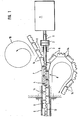
- FIG. 1 shows a drive motor 1, the output shaft 11 of which opens into a worm 4 via a coupling 2, which is indicated schematically at 3.
- This worm engages in a corresponding screw thread, each of which engages half in sections 14 of two parts 7 and 8 of a movement transmission element, denoted overall by 5.
- This movement transmission element 5 is guided in a straight line in a guide 6 shown broken off.
- the parts 7 and 8 of the movement transmission member 5 are inevitably brought together by guide surfaces in front of the engagement area with the screw.
- the part 7 is hinted at 18 in a drum, the part 8 - here for demonstration - is recorded in a memory parallel to the guide 6.
- each part 7 and 8 of the movement transmission element 5 are provided on the mutually facing surfaces with a toothing 9, which is shown trapezoidal in the exemplary embodiment.
- This toothing 9 is preferred wise chosen so that the positive engagement with respect to the force transmission in the direction of the guide 6 produces practically no transverse force component to the longitudinal direction of the guide. This can be easily achieved with involute teeth or the like.
- the guide 6 has a longitudinal slot 12, through which a towing member or the like is guided, which establishes the connection between the end of the movement transmission member 5 facing away from the drive motor and an object to be carried in the direction of the guide 6 .
- the parts 7 and 8 of the movement member 5 are guided and stored apart from one another. In this way, a space-saving arrangement of the entire drive device is achieved.
- the sections 14 of the parts 7 and 8 of the motion transmission member 5 can be connected to each other in different ways the, the connection serving only the correct spacing of the sections 14 required with respect to the toothing 9 and, moreover, enables the parts 7 and 8 to be displaced perpendicular to the direction of the guide 6.
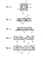
- FIG. 3 shows a first exemplary embodiment of the connection between the sections 14 of a part 7 or 8 of the movement transmission element 5 with the aid of concrete joints with axes 15.
- Figure 4 shows a second embodiment in which the sections 14 are glued to a tape 13 which can be deformed transversely to its longitudinal direction shown.
- FIG. 5 shows the connection between two sections 14, in particular when they are made of plastic, in the form of a joint engagement 16.
- FIG. 6 shows the extraction of sections 14 from a one-piece continuous belt 17, in this respect a toothed belt, in the manufacture of which the exact design of the toothing 9 is particularly simple and the sections are delimited by cutouts 22.
- FIG. 7 shows an embodiment of the kind that can be provided in particular for lower pressure and, above all, tensile loads, for example for the motor-driven movement of windows and / or sunroofs and the like of automobiles.
- the forces occurring in the pushing and pulling direction are so small that the cross section of the belts 21, which remains outside the toothing 9 in the area of the parts 7 and 8, is completely sufficient to absorb the tensile forces occurring in the area of the toothing, which on the movement assembly member 5 formed by joining the parts 7 and 8 in the operation in question here can be exerted on compressive and tensile loads.
- the belts 21 can be deflected in a spatially narrow area from their longitudinal direction corresponding to the guide 6 and into a store - 18 in FIG. 1 - or in a parallel position the guide 6 are brought.
- the band-shaped parts 7 and 8 are brought together by deflecting guides 19 and 20 in such a way that the toothing engagement is already ensured in the area of the worm 4.
- the two parts 7 and 8 are separated and are each bent away from one another by the respective deflection guides 19 and 20 into a storage position parallel to the guide 6, which is formed together with the guide 6 in this exemplary embodiment in a guide body.
- the band-shaped parts 7 and 8 can each be guided in individual grooves, which, starting from the storage position, lead into the area where the parts 7 and 8 are brought together and lead there into a common, wider groove, in the area of which the screw 4 is provided and which in turn leads to the guide 6.
- Such a deflecting guide body can then be closed by a flat cover in such a way that the parts 7 and 8 run in their single deflecting guide as in their merging in channels closed on all sides.
- An overload safety device can be designed particularly simply by making the spindle or worm 4 displaceable under the reaction force of the movement transmission element, which is impeded in its longitudinal displacement movement, against resistance, in particular a spring.
- the spring force indicates the load threshold from which a disability case is assumed.
- the shift can be evaluated in a shutdown process for a drive motor, an alarm trigger and the like.
- the motor or at least its rotor can be designed to be displaceable in the longitudinal direction of the axis of rotation, as a result of which an alarm or shutdown signal can be triggered against a specific spring resistance that can be predetermined by a response threshold .
- this drive With the design of this drive according to the invention, a space-saving, low-noise and particularly economical drive converter with regard to the reduction between the drive motor and the movement transmission member can be made available, the area of application of which is very wide-ranging and which is particularly suitable for the spatially narrow conditions in connection with the actuation of retractable windows, sunroofs and the like of automobiles.
Landscapes
- General Engineering & Computer Science (AREA)
- Engineering & Computer Science (AREA)
- Mechanical Engineering (AREA)
- Transmission Devices (AREA)
- Gear Transmission (AREA)
- Power-Operated Mechanisms For Wings (AREA)
- Gears, Cams (AREA)
- Pinball Game Machines (AREA)
- Forging (AREA)
- Retarders (AREA)
- Body Structure For Vehicles (AREA)
- Crystals, And After-Treatments Of Crystals (AREA)
- Toys (AREA)
Abstract
Description
- Bekannte Getriebe dieser Art sind zum Beispiel Kurbeltriebe, die jedoch in ihrem translatorischen Arbeitsbereich auf den Durchmesser des Kurbelrades beschränkt sind und entsprechenden Platzbedarf aufweisen. Weiterhin sind Schleppkettenantriebe bekannt, die jedoch aufgrund der endlos ausgebildeten Kette zwei Umlenkräder erfordern und eine verhältnismäßig große Masse aufweisen, abgesehen davon, daß die Kettenführung im Bereich der Längstrume Probleme bereiten kann. Bei schließlich noch bekannten Zahnrad-Zahnstangen-Trieben benötigt die Zahnstange den doppelten Raum in Richtung der Translationsbewegung ihres Abtriebspunktes. Grundsätzlich kann der Eingriff zwischen dem Rotationsglied und dem translatorisch versetzbaren Bauteil reibschlüssig- erfolgen, doch bedeutet dies die Gefahr eines Schlupfes bzw. den Aufwand hoher Anpreßkräfte.
- Der Erfindung liegt die Aufgabe zugrunde, ein Getriebe der eingangs genannten Art zu schaffen, das bei Beanspruchung auf Zug und Druck einfach ausgestaltet, reibungs- und massearm ausgebildet ist.
- Ausgehend von einem Getriebe mit den Merkmalen des Oberbegriffes des Anspruches 1 wird diese Aufgabe erfindungsgemäß durch dessen Kennzeichen gelöst.
- Die erfindungsgemäße Ausbildung des Getriebes zeichnet sich dadurch aus, daß die Übertragung einer rotatorischen in eine translatorische Bewegung besonders reibungsarm erfolgt und die Möglichkeit bietet, eine hin- und hergehende transiatorische Bewegung ohne Endlosglieder, wie zum Beispiel Ketten, zur Verfügung zu stellen, obwohl auch eine derartige Ausbildung mit dem erfindungsgemässen Getriebe möglich ist. Wichtig ist, daß das translatorisch bewegte Bewegungsübertragungsgtied sowohl auf Druck als auch auf Zug beanspruchbar ist. Die insgesamt formschlüsse Ausbildung der Übertragungsstrecke zwischen dem rotatorischen Antrieb und dem Bewegungsübertragungsglied und auch dessen formschlüssige Kupplung ergeben ein schlupffreies und damit exakt bestimmbares Bewegungsverhalten.
- Erfindungswesentlich ist, daß das Bewegungsübertragungsglied zwei- oder mehrteilig ausgebildet ist und erst im Rahmen der Führung zu dem eigentlichen Kraftübertragungsglied zusammengeführt wird. Die einzelnen Teile lassen sich aufgrund der Querbeweglichkeit zur Längsrichtung der Führung raumsparend speichern, sei es in Form einer Trommel, oder auch in Form einer Rückführung parallel zur Führungsrichtung.
- Von besonderem Vorteil ist die getriebliche Verbindung zwischen dem Antriebsmotor und dem Bewegungsübertragungsgtied in Form eines Schneckentriebes. Dadurch kann ein Untersetzungsgetriebe eingespart werden. Die Schnecke wird unmittelbar von der Motorachse getrieben, die Übersetzung zwischen Schnecke und dem "Schneckenradgewinde" in den Teilen der Bewegungsübertragungseinrichtung - bei zwei Teilen jeweils hälftig - schafft die für die Schneckentriebe typische besonders hohe Untersetzung.
- Der verzahnte Eingriff zwischen den beiden oder mehreren Teilen des Bewegungsübertragungsgliedes führt dazu, daß nach deren Zusammenführung eine in Bewegungsrichtung formschlüssige Verbindung geschaffen wird, die dazu führt, daß die Kraftübertragung über die Zahnflanken erfolgt und damit die Halterung der Abschnitte, beispielsweise aufgeklebt auf ein verformbares Band, nicht belastet. Dabei kann die Verzahnung derart ausgeführt werden, daß praktisch keine Kraftkomponenten quer zur Bewegungsrichtung auftreten, so daß die Reibungsbetastung innerhalb der Führung vernachlässigbar gering wird.
- Für kleinere Belastungen, insbesondere Zugbelastungen, werden die beiden Teile der Bewegungsübertragungseinrichtung als Bänder ausgeführt, die in ununterbrochener Weise mit einer Verzahnung versehen sind. Die ineinander greifende Verzahnung vereinigt hinsichtlich der Druck- und Zugbelastungen die beiden Teile der Bewegungsübertragungseinrichtung innerhalb der Führung zu einem Ganzen, wobei die Verzahnung insbesondere derart ausgebildet ist, daß sie nach Art eines Reißverschlusses mit Hinterschneidungen zwischen den Zähnen und. den Zahnlücken ausgebildet ist und damit bei Zug- und Druckbelastungen keine Kräfte quer zur Längsrichtung der Teile bzw. der Bewegungsübertragungseinrichtung innerhalb der Führung ausüben. Die Herstellung eines solchen Antriebes ist besonders einfach, hinsichtlich der Reibung innerhalb der Führung praktisch vernachlässigbar und raumsparend anzuordnen, weil unter Berücksichtigung dieser verhältnismäßig kleinen Zugbelastungen die Querschnitte der beiden im zusammengeführten Zustand die Bewegungsübertragungseinrichtung bildenden Teile außerhalb der Verzahnung gering gehalten werden können. Auf diese Weise lassen sich verhältnismäßig enge Umlenkungen im Trennungsbereich der beiden Teile vorsehen. In besonders bevorzugter Ausführung ist in Längsrichtung zwischen der Verzahnung ein Gewinde vorgesehen, in das eine Schnecke oder Schraube eingreift, die unmittelbar mit der Rotorachse eines Antriebsmotors verbunden ist. Das bedeutet, daß beide Teile der zweigeteilten Bewegungsübertragungseinrichtung jeweils die Hälfte eines in Längsrichtung der Teile ausgebildeten Gewindes für die Schnecke aufweisen, und zwar bevorzugt im Mittelbereich der Teile der Bewegungseinrichtung, derart, daß beidseitig der Gewindeausbildung ein Randstreifen mit der Verzahnung 9 verbleibt.
- Diese und weitere bevorzugte Ausführungsformen der Erfindung ergeben sich aus den Unteransprüchen in Zusammenhang mit den in der Zeichnung wiedergegebenen Ausführungsbeispielen, auf die besonders Bezug genommen wird und deren nachfolgende Beschreibung die Erfindung näher erläutert. Es zeigen:
- Figur 1 eine Prinzip-Querschnitts-Darstellung des Getriebes;
- Figur 2 eine Querschnittsdarstellung im Bereich der Führung;
- Figur 3 eine erste Art der Verbindung der Abschnitte eines Teiles der Bewegungsübertragungseinrichtung;
- Figur 4 ein zweites Ausführungsbeispiel der Anordnung der Abschnitte eines Teils der Bewegungsübertragungseinrichtung auf einem Band;
- Figur 5 eine andere Art der Gelenkverbindung zwischen zwei Abschnitten eines Teils der Bewegungsübertragungseinrichtung;
- Figur 6 die Ausformung der Abschnitte eines Teil der Bewegungsübertragungseinrichtung im Rahmen eines einstückigen Bandstreifens;
- Figur 7 eine Prinzip-Querschnittsdarstellung des Getriebes mit einer alternativen Ausführungsform der Bewegungsübertragungseinrichtung in Form durchgehend ausgebildeter Teile der Bewegungsübertragungseinrichtung.
- In Figur 1 ist ein Antriebsmotor 1 dargestellt, dessen Abtriebswelle 11 über eine Kupplung 2, die bei 3 schematisch angedeutet gelagert ist, in einer Schnecke 4 mündet. Diese Schnecke greift in ein entsprechenoes Schraubengewinde ein, das jeweils zur Hälfte in Abschnitten 14 von zwei Teilen 7 und 8 eines insgesamt mit 5 bezeichneten Bewegungsübertragungsgliedes eingreift. Dieses Bewegungsübertragungsglied 5 wird geradlinig in einer abgebrochen dargestellten Führung 6 geführt. Die Teile 7 und 8 des Bewegungsübertragungsgliedes 5 werden vor dem Eingriffsbereich mit der Schnecke durch Leitflächen zwangsläufig zusammengeführt. Der Teil 7 wird andeutungsweise bei 18 in einer Trommel gespeichert, der Teil 8 wird - hier zur Demonstration - in einem Speicher parallel zur Führung 6 aufgenommen.
- Die Abschnitte 14 eines jeden Teiles 7 bzw. 8 des Bewegungsübertragungsgtiedes 5 sind an den einander zugewandten Flächen mit einer Verzahnung 9 versehen, die im Ausführungsbeispiel trapezförmig wiedergegeben ist. Diese Verzahnung 9 wird jedoch vorzugsweise so gewählt, daß der formschlüssige Eingriff hinsichtlich der Kraftübertragung in Richtung der Führung 6 praktisch keine quer zur Führungslängsrichtung verlaufende Kraftkomponente erzeugt. Dies läßt sich mühelos mit einer evolventen Verzahnung oder dergleichen erreichen.
- Die Führung 6 weist einen Längsschlitz 12 auf, durch welchen ein Schleppglied oder dergleichen hindurchgeführt ist, das die Verbindung zwischen dem dem Antriebsmotor abgewandten Ende des Bewegungsübertragungsgliedes 5 und einem in Richtung der Führung 6 mitzunehmenden Gegenstand herstellt.. ;
- Im Bereich der Schnecke bzw. deren der Motorwelle 11 zugewandten Ende werden die Teile 7 und 8 des Bewegungsgliedes 5 voneinander entfernt geführt und gespeichert. Auf diese Weise wird eine platzsparende Anordnung der gesamten Antriebseinrichtung erreicht.
- Aufgrund des hohen Untersetzungsverhältnisses zwischen der Schnekke 4 und dem der Schnecke angepaßten Schraubengewinde 10, das jeweils zur Hälfte in den Abschnitten 14 des Teiles 7 und demjenigen des Teiles 8 des Bewegungsübertragungsgliedes 5 angeordnet ist, ist ein weiteres Untersetzungsgetriebe nicht erforderlich. Diese Antriebseinrichtung ist damit besonders preiswert herzustellen.
- Es ist ohne weiteres verständlich, daß aufgrund der Verzahnung 9, über die die Abschnitte 14 der Teile 7 und :8 der Bewegungsübertragungseinrichtung 5 ineinandergreifen, eine Zug- und Druckbelastung übertragen werden kann. Wie die Zeichnung erkennen läßt, sind die Abschnitte 14 der Teile 7 und 8 derart gegeneinander versetzt angeordnet, daß jeweils Abschnitt 14 beispielsweise des Teiles 7 zwei benachbarte Abschnitte 14 des Teiles 8 überbrükkend verbindet. Damit wird erreicht, daß Zug- und Druckkräfte ausschließlich über die Verzahnung der Abschnitte 14 übertragen werden.
- Die Abschnitte 14 der Teile 7 und 8 des Bewegungsübertragungsgliedes 5 können auf verschiedene Weise miteinander verbunden werden, wobei die Verbindung lediglich der korrekten, hinsichtlich der Verzahnung 9 erforderlichen Beabstandung der Abschnitte 14 dient und im übrigen ermöglicht, daß die Teile 7 und 8 senkrecht zur Richtung der Führung 6 versetzbar sind.
- Figur 3 zeigt ein erstes Ausführungsbeispiel der Verbindung zwischen den Abschnitten 14 eines Teiles 7 bzw. 8 des Bewegungsübertragungsgliedes 5 mit Hilfe von konkreten Gelenken mit Achsen 15.
- Figur 4 zeigt ein zweites Ausführungsbeispiel, bei dem die Abschnitte 14 auf ein Band 13 aufgeklebt sind, das sich quer zu seiner dargestellten Längsrichtung verformen läßt.
- Figur 5 zeigt die Verbindung zwischen zwei Abschnitten 14, insbesondere bei deren Ausführung in Kunststoff, in Form eines Gelenkeingriffes 16.
- Figur 6 zeigt die Gewinnung von Abschnitten 14 aus einem einstükkig durchgehenden Band 17, insoweit also ein Zahnriemen, bei dessen Herstellung die exakte Ausführung der Verzahnung 9 besonders einfach und die Begrenzung der Abschnitte durch Aussparungen 22 getroffen ist.
- Figur 7 zeigt eine Ausführungsform, wie sie insbesondere für geringere Druck- und vor allem Zugbelastungen vorgesehen werden kann, so beispielsweise für die motorisch angetriebene Bewegung von Fenstern und/oder Schiebedächern und dergleichen von Automobilen. Die dabei auftretenden Kräfte in Druck- und Zugrichtung sind so gering, daß der Querschnitt der Bänder 21, der im Bereich der Teile 7 und 8 außerhalb der Verzahnung 9 verbleibt, völlig ausreichend ist, die im Bereich der Verzahnung auftretenden Zugkräfte aufzunehmen, die auf das durch Zusammenfügung der Teile 7 und 8 gebildete Bewegungsübertragungsglied 5 bei dem hier in Frage stehenden Betrieb auf Druck- und Zugbelastung ausgeübt werden. Die Bänder 21 können dabei auf räumlich engem Bereich aus ihrer der Führung 6 entsprechenden Längsrichtung ausgelenkt und in einen Speicher - 18 in Figur 1 - oder in Parallellage zu der Führung 6 gebracht werden.
- Vor dem Eintrittsbereich in die Führung 6 werden die bandförmigen Teile 7 und 8 durch Umlenkführungen 19 und 20 zusammengeführt, derart, daß der Verzahnungseingriff bereits im Bereich der Schnecke 4 sichergestellt ist. Vor diesem Bereich sind die beiden Teile 7 und 8 getrennt und werden jeweils voneinander fort gekrümmt durch die jeweiligen Umlenkführungen 19 bzw. 20 in eine Speicherstellung parallel zur Führung 6 geleitet, die zusammen mit der Führung 6 in diesem Ausführungsbeispiel in einem Führungskörper vereint ausgebildet ist. In praktischer Ausführung kann man die bandförmigen Teile 7 und 8 jeweils in Einzelnuten führen, die von der Speicherstellung ausgehend in den Bereich der Zusammenführung der Teile 7 und 8 führen und dort in eine gemeinsame breitere Nut münden, in deren Bereich die Schnecke 4 vorgesehen ist und die ihrerseits in die Führung 6 überleitet. Durch einen flachen Deckel läßt sich dann ein solcher Umlenkführungskörper derart schließen, daß die Teile 7 und 8 in ihrer Einzel-Umlenkführung wie in ihrer Zusammenführung in allseits geschlossenen Kanälen verlaufen.
- Eine Überlastsicherung läßt sich besonders einfach dadurch gestalten, daß man die Spindel oder Schnecke 4 unter der Reaktionskraft des in seiner Längsverschiebebewegung behinderten Bewegungsübertragungsgliedes gegen einen Widerstand, insbesondere eine Feder, verschiebbar gestaltet. Die Federkraft gibt dabei die Lastschwelle an, ab der ein Behinderungsfall angenommen wird. Die Verschiebung läßt sich in einen Abschaltvorgang für einen Antriebsmotor, eine Alarmauslösung und dergleichen auswerten. Im Falle der direkten Verbindung zwischen dem Rotor des Antriebsmotors 1 und der Schnecke 4 kann der Motor bzw. zumindest sein Rotor entsprechend in Längsrichtung der Rotationsachse verschiebbar ausgebildet sein, wodurch gegen einen bestimmten, eine Ansprechschwelle vorgebbaren Federwiderstand ein Alarm- bzw. Abschattsignat ausgelöst werden kann. Des weiteren ist es möglich, zwischen der Schnecke und den Rotor des Antriebsmotors 1 eine axial spielbehaftete Kupplung 2 einzuschalten, in deren Bereich die federbelastete Notfall-Verschiebung stattfindet, die wiederum zur Signalauslösung ausgenutzt werden kann.
- Mit der erfindungsgemäßen Ausgestaltung dieses Antriebes läßt sich ein raumsparender, geräuscharmer und hinsichtlich der Untersetzung zwischen dem Antriebsmotor und dem Bewegungsübertragungsglied besonders wirtschaftlicher Antriebswandler zur Verfügung stellen, dessen Einsatzbereich weit gespannt ist und der sich vor allem auch für die räumlich engen Verhältnisse im Zusammenhang mit der Betätigung von versenkbaren Fenstern, Schiebedächern und dergleichen von Automobilen einsetzen läßt. Dies gilt vor allem für die schwächere Ausbildung des letzten Ausführungsbeispieles, während die Ausführungen nach den Figuren 1 bis 6 mit Abschnitten für höhere Zugkraftbelastung, wie sie beispielsweise bei Überkopftorantrieben auftreten, eingesetzt werden können.
Claims (23)
dadurch gekennzeichnet,
daß das Bewegungsübertragungsglied (5) in Richtung der Führung (6) gesehen in wenigstens zwei Teile (7, 8) längsgeteilt ausgebitdet ist,
daß die derart gebildeten Teile (7, 8) mit einer Verzahnung (9) versehen in der Führung (6) ineinandergreifen,
daß diese Teile (7, 8) außerhalb der Führung (6) quer zur Führungsrichtung verformbar jeweils für sich getrennt geführt sind und
daß die Teile (7, 8) - insbesondere im zusammengeführten Zustand - über eine Gewindeverbindung (10) getrieblich an den Antrieb (1) angeschlossen sind.
dadurch gekennzeichnet,
daß die Gewindeverbindung als Schneckentrieb (10) ausgebildet ist.
dadurch gekennzeichnet,
daß die Schnecke (4) direkt an die Antriebsmotorachse (11) angeschlossen ist.
dadurch gekennzeichnet,
daß die Führung (6) einen Längsschlitz (12) für den Durchgang eines Anschlußgliedes aufweist, das einen Endes an dem Bewegungsübertragungsglied (5) und anderen Endes an einen mittels des Bewegungsübertragungsgliedes (5) zu bewegenden Gegenstand anschließbar ist.
dadurch gekennzeichnet,
daß das Bewegungsübertragungsglied (5) bzw. dessen Teile (7, 8) einen offenen Strang bilden.
dadurch gekennzeichnet,
daß das dem Antrieb (1) abgewandte Ende des Bewegungsübertragungsgliedes (5) in jeder Bewegungslage innerhalb der Führung (6) verbleibt und an das Anschlußglied angekoppelt ist.
dadurch gekennzeichnet,
daß die Teile (7, 8) des Bewegungsübertragungsgliedes (5) aus einer aufeinanderfolgenden Reihe auf ein quer zur Führungsrichtung verformbares Band (13) aufgebrachter, insbesondere aufgektebter Abschnitte (14) bestehen.
dadurch gekennzeichnet,
daß die aufeinanderfolgenden Abschnitte (14) aneinander angelenkt (15) sind.
dadurch gekennzeichnet,
daß die Abschnitte (14) als Kunststoffteile ausgebildet sind, die ohne eigenständige Achsen gelenkig ineinandergreifend (16) ausgebildet sind.
dadurch gekennzeichnet,
daß die Abschnitte (14) einstückig als Bestandteile eines Bandes (17) ausgebildet sind.
dadurch gekennzeichnet,
daß die Abschnitte (14) durch von der Verzahnung (9) her gesehen geführte Aussparungen (22) innerhalb des Bandes (17) gebildet sind.
dadurch gekennzeichnet,
daß die Abschnitte (14) der Teile (7, 8) in der Führung (6) einander überlappend angeordnet sind und daß die Abschnitte (14) über die Verzahnung (9) derart ineinandergreifen, daß jeder Abschnitt (14) des einen Teils (7 bzw. 8) in jeden der gegenüberliegenden Abschnitte des anderen Teiles (8 bzw. 7) im zusammengeführten Zustand in Zug- und Druckrichtung formschlüssig eingreift.
dadurch gekennzeichnet,
daß jeder Abschnitt (14) wenigstens drei Zähne und zwei Zahnlücken aufweist und daß innerhalb der Führung eine weitere Zahnlücke jeweils zwischen zwei benachbarten Abschnitten (14) der Abschnittreihe eines jeden der Teile (7, 8) gebildet ist, in die ein mittlerer Zahn des jeweils gegenüberliegenden Abschnittes (14) eingreift.
dadurch gekennzeichnet,
daß die Teile (7, 8) jeweils durchgehend mit einer nicht unterteilten Verzahnung (9) versehen sind, wobei die Teile (7, 8) in ihrem bezüglich der Zähne der Verzahnung (9) gesehen verbleibenden Bandquerschnitt senkrecht zur Längsrichtung der Führung (6) gesehen nach Werkstoff und/oder Dicke leicht verformbar ausgebildet sind.
dadurch gekennzeichnet,
daß die Verzahnung (9) ein steilflankiges Trapezgewinde ist.
dadurch gekennzeichnet,
daß die Verzahnung evolventenförmige oder dergleichen Flanken aufweist, derart, daß die Kraftübertragung innerhalb der Führung (6) praktisch nur in Führungsrichtung und ohne nennenswerte Querkomponente stattfindet.
dadurch gekennzeichnet,
daß die Verzahnung (9) Zähne aufweist, die in ihrem vom Mittelbereich her gesehen zum Kopf hin gerichteten Bereich verbreitert ausgebildet sind und in Zahnlücken eingreifen, die in ihrem von der Mitte aus zum Zahntückengrund hin gesehenen Bereich verbreitert ausgeführt sind, derart, daß die Zähne und Zahnlücken jeweils zueinander quer zur Längsrichtung der Teile (7, 8) hinterschnitten ausgebildet sind.
dadurch gekennzeichnet,
daß die Teile (7, 8) zwangsgeführt ineinandergreifend gehalten sind.
dadurch gekennzeichnet,
daß die außerhalb der Führung (6) befindlichen Teile (7, 8) in einem Trommelspeicher (18) gehalten sind.
dadurch gekennzeichnet,
daß die Teile (7, 8) außerhalb der Führung (6) etwa parallel zu dieser verlaufend geführt sind.
dadurch gekennzeichnet,
daß die Schnecke (4) - insbesondere in Längsrichtung ihrer, Rotationsachse, unter dem Reaktionsdruck des in seiner Längsbeweglichkeit behinderten Bewegungsübertragungsgliedes aus den Teilen (7, 8) gegen einen Widerstand, insbesondere eine Feder, über eine bestimmte Signalstrecke verschiebbar gelagert ist.
dadurch gekennzeichnet,
daß der über die Welle (11) starr mit der Schnecke (4) verbundene Antriebsmotor (1) bzw. dessen- Rotor um die Signalstrecke in Richtung seiner Rotationsachse verschiebbar gelagert ist.
dadurch gekennzeichnet,
daß in die Welle (11) eine axial spielbehaftete Kupplung (2) eingeschaltet ist.
Priority Applications (1)
| Application Number | Priority Date | Filing Date | Title |
|---|---|---|---|
| AT85106362T ATE37938T1 (de) | 1984-05-24 | 1985-05-23 | Getriebe zur ueberfuehrung einer rotatorischen in eine translatorische bewegung. |
Applications Claiming Priority (2)
| Application Number | Priority Date | Filing Date | Title |
|---|---|---|---|
| DE3419477 | 1984-05-24 | ||
| DE3419477A DE3419477C1 (de) | 1984-05-24 | 1984-05-24 | Getriebe zur UEberfuehrung einer rotatorischen in eine translatorische Bewegung |
Publications (3)
| Publication Number | Publication Date |
|---|---|
| EP0165497A2 true EP0165497A2 (de) | 1985-12-27 |
| EP0165497A3 EP0165497A3 (en) | 1986-07-23 |
| EP0165497B1 EP0165497B1 (de) | 1988-10-12 |
Family
ID=6236797
Family Applications (1)
| Application Number | Title | Priority Date | Filing Date |
|---|---|---|---|
| EP85106362A Expired EP0165497B1 (de) | 1984-05-24 | 1985-05-23 | Getriebe zur Überführung einer rotatorischen in eine translatorische Bewegung |
Country Status (14)
| Country | Link |
|---|---|
| US (1) | US4726247A (de) |
| EP (1) | EP0165497B1 (de) |
| JP (1) | JPS612960A (de) |
| KR (1) | KR920008023B1 (de) |
| AT (1) | ATE37938T1 (de) |
| BR (1) | BR8502434A (de) |
| CA (1) | CA1261649A (de) |
| DD (1) | DD233868A5 (de) |
| DE (2) | DE3419477C1 (de) |
| ES (1) | ES8608125A1 (de) |
| GR (1) | GR851093B (de) |
| MX (1) | MX158705A (de) |
| SU (1) | SU1471954A3 (de) |
| ZA (1) | ZA853744B (de) |
Cited By (4)
| Publication number | Priority date | Publication date | Assignee | Title |
|---|---|---|---|---|
| EP0232803A1 (de) * | 1986-02-01 | 1987-08-19 | HÖRMANN KG ANTRIEBS- und STEUERUNGSTECHNIK | Getriebe zur Überführung einer rotatorischen in eine translatorische Bewegung |
| GB2258521A (en) * | 1991-08-08 | 1993-02-10 | Rheinmetall Gmbh | Ammunition positioning |
| EP0534413A1 (de) * | 1991-09-24 | 1993-03-31 | Aug. Winkhaus GmbH & Co. KG | Betätigungsvorrichtung für einen Flügel eines Fensters, einer Tür, einer Lüftungsklappe oder dergleichen |
| EP2520827A3 (de) * | 2011-05-02 | 2013-09-04 | Waagner-Biro Austria Stage Systems AG | Hebevorrichtung zum vertikalen Anheben von Lasten |
Families Citing this family (169)
| Publication number | Priority date | Publication date | Assignee | Title |
|---|---|---|---|---|
| DE3603122A1 (de) * | 1986-02-01 | 1987-08-06 | Hoermann Kg Antrieb Steuertec | Getriebe zur ueberfuehrung einer rotatorischen in eine translatorische bewegung |
| JPH01319099A (ja) * | 1988-06-17 | 1989-12-25 | Matsushita Electric Ind Co Ltd | 音声認識装置 |
| JPH02118699A (ja) * | 1988-10-28 | 1990-05-02 | Matsushita Electric Ind Co Ltd | 音声認識装置 |
| JPH0727519Y2 (ja) * | 1988-11-21 | 1995-06-21 | ソニー株式会社 | 音声認識装置 |
| JP2658426B2 (ja) * | 1989-09-26 | 1997-09-30 | 松下電器産業株式会社 | 音声認識方法 |
| DE9006391U1 (de) * | 1990-06-06 | 1991-10-10 | Marantec Antriebs-und Steuerungstechnik GmbH & Co, Produktions-oHG, 4834 Marienfeld | Getriebe zur Überführung einer rotatorischen in eine translatorische Bewegung |
| DE4018159A1 (de) * | 1990-06-06 | 1991-12-12 | Marantec Antrieb Steuerung | Getriebe zur ueberfuehrung einer rotatorischen in eine translatorische bewegung |
| DE4210523A1 (de) * | 1992-03-31 | 1993-10-07 | Alltronik Ges Zur Herstellung | Kombinierter Schub- und Zugantrieb |
| DE29706739U1 (de) * | 1997-04-15 | 1997-06-12 | Grasl, Andreas, Ing., Heiligeneich | Einrichtung zur Übertragung einer Kraft, insbesondere Druckkraft, längs einer im wesentlichen geraden Strecke |
| US6172475B1 (en) | 1998-09-28 | 2001-01-09 | The Chamberlain Group, Inc. | Movable barrier operator |
| DK174502B1 (da) | 1999-03-31 | 2003-04-28 | Vkr Holding As | Vindues- eller døroperator med dobbeltkædeudstiller |
| EP1319111A4 (de) | 2000-09-22 | 2014-10-01 | Tower Solutions Llc | Einziehbare stütze und verfahren zur herstellung |
| FR2817277B1 (fr) * | 2000-11-27 | 2003-09-26 | Somfy | Dispositif d'entrainement de porte de garage ou analogues |
| FR2826422B1 (fr) * | 2001-06-26 | 2003-11-14 | Serapid France | Actionneur lineaire a courroie |
| IES20020132A2 (en) * | 2002-02-21 | 2003-04-16 | Simon Betson | An actuator |
| US7082720B2 (en) * | 2002-06-25 | 2006-08-01 | Sumitomo Wiring Systems, Ltd. | Cable guide and power supply apparatus for a vehicle slide door |
| WO2004094790A2 (en) | 2003-04-17 | 2004-11-04 | Tower Solutions, Llc | Extendable/retractable support column |
| US20070084897A1 (en) | 2003-05-20 | 2007-04-19 | Shelton Frederick E Iv | Articulating surgical stapling instrument incorporating a two-piece e-beam firing mechanism |
| US9060770B2 (en) | 2003-05-20 | 2015-06-23 | Ethicon Endo-Surgery, Inc. | Robotically-driven surgical instrument with E-beam driver |
| DE10346861B4 (de) * | 2003-10-09 | 2015-03-05 | Stg-Beikirch Industrieelektronik + Sicherheitstechnik Gmbh & Co. Kg | Ausstellvorrichtung |
| US9072535B2 (en) | 2011-05-27 | 2015-07-07 | Ethicon Endo-Surgery, Inc. | Surgical stapling instruments with rotatable staple deployment arrangements |
| US11998198B2 (en) | 2004-07-28 | 2024-06-04 | Cilag Gmbh International | Surgical stapling instrument incorporating a two-piece E-beam firing mechanism |
| US11896225B2 (en) | 2004-07-28 | 2024-02-13 | Cilag Gmbh International | Staple cartridge comprising a pan |
| US7669746B2 (en) | 2005-08-31 | 2010-03-02 | Ethicon Endo-Surgery, Inc. | Staple cartridges for forming staples having differing formed staple heights |
| US11246590B2 (en) | 2005-08-31 | 2022-02-15 | Cilag Gmbh International | Staple cartridge including staple drivers having different unfired heights |
| US10159482B2 (en) | 2005-08-31 | 2018-12-25 | Ethicon Llc | Fastener cartridge assembly comprising a fixed anvil and different staple heights |
| US11793518B2 (en) | 2006-01-31 | 2023-10-24 | Cilag Gmbh International | Powered surgical instruments with firing system lockout arrangements |
| US8708213B2 (en) | 2006-01-31 | 2014-04-29 | Ethicon Endo-Surgery, Inc. | Surgical instrument having a feedback system |
| US8186555B2 (en) | 2006-01-31 | 2012-05-29 | Ethicon Endo-Surgery, Inc. | Motor-driven surgical cutting and fastening instrument with mechanical closure system |
| US7845537B2 (en) | 2006-01-31 | 2010-12-07 | Ethicon Endo-Surgery, Inc. | Surgical instrument having recording capabilities |
| DE102006018965A1 (de) * | 2006-04-19 | 2007-10-25 | Karl Neff | Ausfahrbare Säule |
| US11980366B2 (en) | 2006-10-03 | 2024-05-14 | Cilag Gmbh International | Surgical instrument |
| US8632535B2 (en) | 2007-01-10 | 2014-01-21 | Ethicon Endo-Surgery, Inc. | Interlock and surgical instrument including same |
| US8684253B2 (en) | 2007-01-10 | 2014-04-01 | Ethicon Endo-Surgery, Inc. | Surgical instrument with wireless communication between a control unit of a robotic system and remote sensor |
| US8827133B2 (en) | 2007-01-11 | 2014-09-09 | Ethicon Endo-Surgery, Inc. | Surgical stapling device having supports for a flexible drive mechanism |
| ITBO20070066A1 (it) * | 2007-02-01 | 2008-08-02 | Franceschi Daniele De | Serratura polifunzione e servomotore ad organo attuatore avvolgibile su rocchetto intercambiabile |
| US8931682B2 (en) | 2007-06-04 | 2015-01-13 | Ethicon Endo-Surgery, Inc. | Robotically-controlled shaft based rotary drive systems for surgical instruments |
| US11564682B2 (en) | 2007-06-04 | 2023-01-31 | Cilag Gmbh International | Surgical stapler device |
| US11849941B2 (en) | 2007-06-29 | 2023-12-26 | Cilag Gmbh International | Staple cartridge having staple cavities extending at a transverse angle relative to a longitudinal cartridge axis |
| US8573465B2 (en) | 2008-02-14 | 2013-11-05 | Ethicon Endo-Surgery, Inc. | Robotically-controlled surgical end effector system with rotary actuated closure systems |
| RU2493788C2 (ru) | 2008-02-14 | 2013-09-27 | Этикон Эндо-Серджери, Инк. | Хирургический режущий и крепежный инструмент, имеющий радиочастотные электроды |
| US11986183B2 (en) | 2008-02-14 | 2024-05-21 | Cilag Gmbh International | Surgical cutting and fastening instrument comprising a plurality of sensors to measure an electrical parameter |
| US20130153641A1 (en) | 2008-02-15 | 2013-06-20 | Ethicon Endo-Surgery, Inc. | Releasable layer of material and surgical end effector having the same |
| US9005230B2 (en) | 2008-09-23 | 2015-04-14 | Ethicon Endo-Surgery, Inc. | Motorized surgical instrument |
| US8210411B2 (en) | 2008-09-23 | 2012-07-03 | Ethicon Endo-Surgery, Inc. | Motor-driven surgical cutting instrument |
| US11648005B2 (en) | 2008-09-23 | 2023-05-16 | Cilag Gmbh International | Robotically-controlled motorized surgical instrument with an end effector |
| US9386983B2 (en) | 2008-09-23 | 2016-07-12 | Ethicon Endo-Surgery, Llc | Robotically-controlled motorized surgical instrument |
| US8608045B2 (en) | 2008-10-10 | 2013-12-17 | Ethicon Endo-Sugery, Inc. | Powered surgical cutting and stapling apparatus with manually retractable firing system |
| DE102010020410A1 (de) * | 2010-05-12 | 2011-11-17 | Gröninger Antriebstechnik GmbH & Co. KG | Bandantrieb für Zug- und Druckbeanspruchung |
| US9248576B2 (en) * | 2010-05-31 | 2016-02-02 | National Institute Of Advanced Industrial Science And Technology | Direct acting extensible and retractable arm mechanism, and robot arm provided with direct acting extensible and retractable arm mechanism |
| US9861361B2 (en) | 2010-09-30 | 2018-01-09 | Ethicon Llc | Releasable tissue thickness compensator and fastener cartridge having the same |
| US10945731B2 (en) | 2010-09-30 | 2021-03-16 | Ethicon Llc | Tissue thickness compensator comprising controlled release and expansion |
| US11812965B2 (en) | 2010-09-30 | 2023-11-14 | Cilag Gmbh International | Layer of material for a surgical end effector |
| US9629814B2 (en) | 2010-09-30 | 2017-04-25 | Ethicon Endo-Surgery, Llc | Tissue thickness compensator configured to redistribute compressive forces |
| US9386988B2 (en) | 2010-09-30 | 2016-07-12 | Ethicon End-Surgery, LLC | Retainer assembly including a tissue thickness compensator |
| US11925354B2 (en) | 2010-09-30 | 2024-03-12 | Cilag Gmbh International | Staple cartridge comprising staples positioned within a compressible portion thereof |
| JP4850964B1 (ja) * | 2010-10-27 | 2012-01-11 | 株式会社椿本チエイン | 噛合チェーン式進退作動装置 |
| EP2633221A4 (de) * | 2010-10-29 | 2018-02-14 | Tower Solutions, LLC | Aus- und einziehbare stützsäule |
| CN104053407B (zh) | 2011-04-29 | 2016-10-26 | 伊西康内外科公司 | 包括定位在其可压缩部分内的钉的钉仓 |
| JP6305979B2 (ja) | 2012-03-28 | 2018-04-04 | エシコン・エンド−サージェリィ・インコーポレイテッドEthicon Endo−Surgery,Inc. | 複数の層を含む組織厚さコンペンセーター |
| JP6105041B2 (ja) | 2012-03-28 | 2017-03-29 | エシコン・エンド−サージェリィ・インコーポレイテッドEthicon Endo−Surgery,Inc. | 低圧環境を画定するカプセルを含む組織厚コンペンセーター |
| US9101358B2 (en) | 2012-06-15 | 2015-08-11 | Ethicon Endo-Surgery, Inc. | Articulatable surgical instrument comprising a firing drive |
| US20140001231A1 (en) | 2012-06-28 | 2014-01-02 | Ethicon Endo-Surgery, Inc. | Firing system lockout arrangements for surgical instruments |
| US9289256B2 (en) | 2012-06-28 | 2016-03-22 | Ethicon Endo-Surgery, Llc | Surgical end effectors having angled tissue-contacting surfaces |
| MX368026B (es) | 2013-03-01 | 2019-09-12 | Ethicon Endo Surgery Inc | Instrumento quirúrgico articulable con vías conductoras para la comunicación de la señal. |
| US9629629B2 (en) | 2013-03-14 | 2017-04-25 | Ethicon Endo-Surgey, LLC | Control systems for surgical instruments |
| US20150053746A1 (en) | 2013-08-23 | 2015-02-26 | Ethicon Endo-Surgery, Inc. | Torque optimization for surgical instruments |
| SG11201607647YA (en) * | 2014-03-14 | 2016-10-28 | Life Robotics Inc | Extensible arm mechanism and robot arm |
| US9733663B2 (en) | 2014-03-26 | 2017-08-15 | Ethicon Llc | Power management through segmented circuit and variable voltage protection |
| US10426476B2 (en) | 2014-09-26 | 2019-10-01 | Ethicon Llc | Circular fastener cartridges for applying radially expandable fastener lines |
| US20150297222A1 (en) | 2014-04-16 | 2015-10-22 | Ethicon Endo-Surgery, Inc. | Fastener cartridges including extensions having different configurations |
| BR112016023698B1 (pt) | 2014-04-16 | 2022-07-26 | Ethicon Endo-Surgery, Llc | Cartucho de prendedores para uso com um instrumento cirúrgico |
| CN106456158B (zh) | 2014-04-16 | 2019-02-05 | 伊西康内外科有限责任公司 | 包括非一致紧固件的紧固件仓 |
| JP6532889B2 (ja) | 2014-04-16 | 2019-06-19 | エシコン エルエルシーEthicon LLC | 締結具カートリッジ組立体及びステープル保持具カバー配置構成 |
| BR112017004361B1 (pt) | 2014-09-05 | 2023-04-11 | Ethicon Llc | Sistema eletrônico para um instrumento cirúrgico |
| US10105142B2 (en) | 2014-09-18 | 2018-10-23 | Ethicon Llc | Surgical stapler with plurality of cutting elements |
| US9924944B2 (en) | 2014-10-16 | 2018-03-27 | Ethicon Llc | Staple cartridge comprising an adjunct material |
| US10517594B2 (en) | 2014-10-29 | 2019-12-31 | Ethicon Llc | Cartridge assemblies for surgical staplers |
| US10736636B2 (en) | 2014-12-10 | 2020-08-11 | Ethicon Llc | Articulatable surgical instrument system |
| US9987000B2 (en) | 2014-12-18 | 2018-06-05 | Ethicon Llc | Surgical instrument assembly comprising a flexible articulation system |
| US10085748B2 (en) | 2014-12-18 | 2018-10-02 | Ethicon Llc | Locking arrangements for detachable shaft assemblies with articulatable surgical end effectors |
| US11154301B2 (en) | 2015-02-27 | 2021-10-26 | Cilag Gmbh International | Modular stapling assembly |
| US10441279B2 (en) | 2015-03-06 | 2019-10-15 | Ethicon Llc | Multiple level thresholds to modify operation of powered surgical instruments |
| US10390825B2 (en) | 2015-03-31 | 2019-08-27 | Ethicon Llc | Surgical instrument with progressive rotary drive systems |
| US10105139B2 (en) | 2015-09-23 | 2018-10-23 | Ethicon Llc | Surgical stapler having downstream current-based motor control |
| US11890015B2 (en) | 2015-09-30 | 2024-02-06 | Cilag Gmbh International | Compressible adjunct with crossing spacer fibers |
| US20170086829A1 (en) | 2015-09-30 | 2017-03-30 | Ethicon Endo-Surgery, Llc | Compressible adjunct with intermediate supporting structures |
| US10292704B2 (en) | 2015-12-30 | 2019-05-21 | Ethicon Llc | Mechanisms for compensating for battery pack failure in powered surgical instruments |
| US11213293B2 (en) | 2016-02-09 | 2022-01-04 | Cilag Gmbh International | Articulatable surgical instruments with single articulation link arrangements |
| US10448948B2 (en) | 2016-02-12 | 2019-10-22 | Ethicon Llc | Mechanisms for compensating for drivetrain failure in powered surgical instruments |
| US10357247B2 (en) | 2016-04-15 | 2019-07-23 | Ethicon Llc | Surgical instrument with multiple program responses during a firing motion |
| US20170296173A1 (en) | 2016-04-18 | 2017-10-19 | Ethicon Endo-Surgery, Llc | Method for operating a surgical instrument |
| DE102016006302A1 (de) * | 2016-05-27 | 2017-11-30 | B. Ketterer Söhne GmbH & Co. KG | Höhenverstelleinrichtung für ein Möbel |
| US11160551B2 (en) | 2016-12-21 | 2021-11-02 | Cilag Gmbh International | Articulatable surgical stapling instruments |
| US10568626B2 (en) | 2016-12-21 | 2020-02-25 | Ethicon Llc | Surgical instruments with jaw opening features for increasing a jaw opening distance |
| US10758230B2 (en) | 2016-12-21 | 2020-09-01 | Ethicon Llc | Surgical instrument with primary and safety processors |
| US11090048B2 (en) | 2016-12-21 | 2021-08-17 | Cilag Gmbh International | Method for resetting a fuse of a surgical instrument shaft |
| JP7010956B2 (ja) | 2016-12-21 | 2022-01-26 | エシコン エルエルシー | 組織をステープル留めする方法 |
| US10307170B2 (en) | 2017-06-20 | 2019-06-04 | Ethicon Llc | Method for closed loop control of motor velocity of a surgical stapling and cutting instrument |
| US10779820B2 (en) | 2017-06-20 | 2020-09-22 | Ethicon Llc | Systems and methods for controlling motor speed according to user input for a surgical instrument |
| US11678880B2 (en) | 2017-06-28 | 2023-06-20 | Cilag Gmbh International | Surgical instrument comprising a shaft including a housing arrangement |
| USD906355S1 (en) | 2017-06-28 | 2020-12-29 | Ethicon Llc | Display screen or portion thereof with a graphical user interface for a surgical instrument |
| US10932772B2 (en) | 2017-06-29 | 2021-03-02 | Ethicon Llc | Methods for closed loop velocity control for robotic surgical instrument |
| US11974742B2 (en) | 2017-08-03 | 2024-05-07 | Cilag Gmbh International | Surgical system comprising an articulation bailout |
| US11944300B2 (en) | 2017-08-03 | 2024-04-02 | Cilag Gmbh International | Method for operating a surgical system bailout |
| US11134944B2 (en) | 2017-10-30 | 2021-10-05 | Cilag Gmbh International | Surgical stapler knife motion controls |
| US10842490B2 (en) | 2017-10-31 | 2020-11-24 | Ethicon Llc | Cartridge body design with force reduction based on firing completion |
| US10779826B2 (en) | 2017-12-15 | 2020-09-22 | Ethicon Llc | Methods of operating surgical end effectors |
| US10835330B2 (en) | 2017-12-19 | 2020-11-17 | Ethicon Llc | Method for determining the position of a rotatable jaw of a surgical instrument attachment assembly |
| US11364027B2 (en) | 2017-12-21 | 2022-06-21 | Cilag Gmbh International | Surgical instrument comprising speed control |
| US10920444B2 (en) | 2018-03-22 | 2021-02-16 | Tower Solutions, Llc | Mobile tower for transportation and remote deployment |
| US11291440B2 (en) | 2018-08-20 | 2022-04-05 | Cilag Gmbh International | Method for operating a powered articulatable surgical instrument |
| US11207065B2 (en) | 2018-08-20 | 2021-12-28 | Cilag Gmbh International | Method for fabricating surgical stapler anvils |
| US11696761B2 (en) | 2019-03-25 | 2023-07-11 | Cilag Gmbh International | Firing drive arrangements for surgical systems |
| US11903581B2 (en) | 2019-04-30 | 2024-02-20 | Cilag Gmbh International | Methods for stapling tissue using a surgical instrument |
| US11771419B2 (en) | 2019-06-28 | 2023-10-03 | Cilag Gmbh International | Packaging for a replaceable component of a surgical stapling system |
| US11350938B2 (en) | 2019-06-28 | 2022-06-07 | Cilag Gmbh International | Surgical instrument comprising an aligned rfid sensor |
| US11684434B2 (en) | 2019-06-28 | 2023-06-27 | Cilag Gmbh International | Surgical RFID assemblies for instrument operational setting control |
| US12035913B2 (en) | 2019-12-19 | 2024-07-16 | Cilag Gmbh International | Staple cartridge comprising a deployable knife |
| US11701111B2 (en) | 2019-12-19 | 2023-07-18 | Cilag Gmbh International | Method for operating a surgical stapling instrument |
| JP7314857B2 (ja) * | 2020-04-30 | 2023-07-26 | トヨタ自動車株式会社 | 伸縮機構及び移動体 |
| US11857182B2 (en) | 2020-07-28 | 2024-01-02 | Cilag Gmbh International | Surgical instruments with combination function articulation joint arrangements |
| US11779330B2 (en) | 2020-10-29 | 2023-10-10 | Cilag Gmbh International | Surgical instrument comprising a jaw alignment system |
| US12053175B2 (en) | 2020-10-29 | 2024-08-06 | Cilag Gmbh International | Surgical instrument comprising a stowed closure actuator stop |
| USD1013170S1 (en) | 2020-10-29 | 2024-01-30 | Cilag Gmbh International | Surgical instrument assembly |
| US11931025B2 (en) | 2020-10-29 | 2024-03-19 | Cilag Gmbh International | Surgical instrument comprising a releasable closure drive lock |
| US11896217B2 (en) | 2020-10-29 | 2024-02-13 | Cilag Gmbh International | Surgical instrument comprising an articulation lock |
| US11849943B2 (en) | 2020-12-02 | 2023-12-26 | Cilag Gmbh International | Surgical instrument with cartridge release mechanisms |
| US11737751B2 (en) | 2020-12-02 | 2023-08-29 | Cilag Gmbh International | Devices and methods of managing energy dissipated within sterile barriers of surgical instrument housings |
| US11744581B2 (en) | 2020-12-02 | 2023-09-05 | Cilag Gmbh International | Powered surgical instruments with multi-phase tissue treatment |
| US11890010B2 (en) | 2020-12-02 | 2024-02-06 | Cllag GmbH International | Dual-sided reinforced reload for surgical instruments |
| US11944296B2 (en) | 2020-12-02 | 2024-04-02 | Cilag Gmbh International | Powered surgical instruments with external connectors |
| US11653915B2 (en) | 2020-12-02 | 2023-05-23 | Cilag Gmbh International | Surgical instruments with sled location detection and adjustment features |
| US11896094B2 (en) * | 2021-02-22 | 2024-02-13 | Casey P. Coe | Wearable multipurpose umbrella |
| US12108951B2 (en) | 2021-02-26 | 2024-10-08 | Cilag Gmbh International | Staple cartridge comprising a sensing array and a temperature control system |
| US11980362B2 (en) | 2021-02-26 | 2024-05-14 | Cilag Gmbh International | Surgical instrument system comprising a power transfer coil |
| US11744583B2 (en) | 2021-02-26 | 2023-09-05 | Cilag Gmbh International | Distal communication array to tune frequency of RF systems |
| US11749877B2 (en) | 2021-02-26 | 2023-09-05 | Cilag Gmbh International | Stapling instrument comprising a signal antenna |
| US11950777B2 (en) | 2021-02-26 | 2024-04-09 | Cilag Gmbh International | Staple cartridge comprising an information access control system |
| US11812964B2 (en) | 2021-02-26 | 2023-11-14 | Cilag Gmbh International | Staple cartridge comprising a power management circuit |
| US11696757B2 (en) | 2021-02-26 | 2023-07-11 | Cilag Gmbh International | Monitoring of internal systems to detect and track cartridge motion status |
| US11723657B2 (en) | 2021-02-26 | 2023-08-15 | Cilag Gmbh International | Adjustable communication based on available bandwidth and power capacity |
| US11751869B2 (en) | 2021-02-26 | 2023-09-12 | Cilag Gmbh International | Monitoring of multiple sensors over time to detect moving characteristics of tissue |
| US11793514B2 (en) | 2021-02-26 | 2023-10-24 | Cilag Gmbh International | Staple cartridge comprising sensor array which may be embedded in cartridge body |
| US11701113B2 (en) | 2021-02-26 | 2023-07-18 | Cilag Gmbh International | Stapling instrument comprising a separate power antenna and a data transfer antenna |
| US11730473B2 (en) | 2021-02-26 | 2023-08-22 | Cilag Gmbh International | Monitoring of manufacturing life-cycle |
| US11737749B2 (en) | 2021-03-22 | 2023-08-29 | Cilag Gmbh International | Surgical stapling instrument comprising a retraction system |
| US11723658B2 (en) | 2021-03-22 | 2023-08-15 | Cilag Gmbh International | Staple cartridge comprising a firing lockout |
| US11759202B2 (en) | 2021-03-22 | 2023-09-19 | Cilag Gmbh International | Staple cartridge comprising an implantable layer |
| US11806011B2 (en) | 2021-03-22 | 2023-11-07 | Cilag Gmbh International | Stapling instrument comprising tissue compression systems |
| US11826042B2 (en) | 2021-03-22 | 2023-11-28 | Cilag Gmbh International | Surgical instrument comprising a firing drive including a selectable leverage mechanism |
| US11717291B2 (en) | 2021-03-22 | 2023-08-08 | Cilag Gmbh International | Staple cartridge comprising staples configured to apply different tissue compression |
| US11826012B2 (en) | 2021-03-22 | 2023-11-28 | Cilag Gmbh International | Stapling instrument comprising a pulsed motor-driven firing rack |
| US11786243B2 (en) | 2021-03-24 | 2023-10-17 | Cilag Gmbh International | Firing members having flexible portions for adapting to a load during a surgical firing stroke |
| US11786239B2 (en) | 2021-03-24 | 2023-10-17 | Cilag Gmbh International | Surgical instrument articulation joint arrangements comprising multiple moving linkage features |
| US11744603B2 (en) | 2021-03-24 | 2023-09-05 | Cilag Gmbh International | Multi-axis pivot joints for surgical instruments and methods for manufacturing same |
| US11896218B2 (en) | 2021-03-24 | 2024-02-13 | Cilag Gmbh International | Method of using a powered stapling device |
| US12102323B2 (en) | 2021-03-24 | 2024-10-01 | Cilag Gmbh International | Rotary-driven surgical stapling assembly comprising a floatable component |
| US11832816B2 (en) | 2021-03-24 | 2023-12-05 | Cilag Gmbh International | Surgical stapling assembly comprising nonplanar staples and planar staples |
| US11857183B2 (en) | 2021-03-24 | 2024-01-02 | Cilag Gmbh International | Stapling assembly components having metal substrates and plastic bodies |
| US11849944B2 (en) | 2021-03-24 | 2023-12-26 | Cilag Gmbh International | Drivers for fastener cartridge assemblies having rotary drive screws |
| US11896219B2 (en) | 2021-03-24 | 2024-02-13 | Cilag Gmbh International | Mating features between drivers and underside of a cartridge deck |
| US11793516B2 (en) | 2021-03-24 | 2023-10-24 | Cilag Gmbh International | Surgical staple cartridge comprising longitudinal support beam |
| US11903582B2 (en) | 2021-03-24 | 2024-02-20 | Cilag Gmbh International | Leveraging surfaces for cartridge installation |
| US11849945B2 (en) | 2021-03-24 | 2023-12-26 | Cilag Gmbh International | Rotary-driven surgical stapling assembly comprising eccentrically driven firing member |
| US20220378426A1 (en) | 2021-05-28 | 2022-12-01 | Cilag Gmbh International | Stapling instrument comprising a mounted shaft orientation sensor |
| US11980363B2 (en) | 2021-10-18 | 2024-05-14 | Cilag Gmbh International | Row-to-row staple array variations |
| US11937816B2 (en) | 2021-10-28 | 2024-03-26 | Cilag Gmbh International | Electrical lead arrangements for surgical instruments |
| US12089841B2 (en) | 2021-10-28 | 2024-09-17 | Cilag CmbH International | Staple cartridge identification systems |
Citations (9)
| Publication number | Priority date | Publication date | Assignee | Title |
|---|---|---|---|---|
| US2574657A (en) * | 1945-10-23 | 1951-11-13 | Harold C Pierce | Flexible power transmitting mechanism |
| US3153942A (en) * | 1960-12-27 | 1964-10-27 | Gen Electric | Linear actuating arrangement |
| DE1198159B (de) * | 1964-02-22 | 1965-08-05 | Fritz Eller | Spindelantrieb mit auf der Spindel laufender Spindelmutter |
| GB1085443A (en) * | 1964-03-14 | 1967-10-04 | Continental Gummi Werke Ag | Improved driving belt assembly |
| FR1536676A (fr) * | 1967-09-12 | 1968-08-16 | Honeywell Inc | Perfectionnement aux dispositifs d'entraînement |
| DE1936918A1 (de) * | 1969-07-19 | 1971-01-28 | Vogel Dr Ing Rudolf | Aufzug |
| DE2162938B2 (de) * | 1971-12-18 | 1976-09-30 | Kernforschungsanlage Jülich GmbH, 517OJülich | Schub- und zugelement |
| DE2848541B1 (de) * | 1978-11-09 | 1980-03-27 | Kombi Lift Montage Gmbh | Hydraulische Vorrichtung zum Betrieb eines Aufzuges |
| US4473365A (en) * | 1980-11-26 | 1984-09-25 | Lapeyre James M | Detachable link chain |
Family Cites Families (17)
| Publication number | Priority date | Publication date | Assignee | Title |
|---|---|---|---|---|
| US1850160A (en) * | 1928-03-09 | 1932-03-22 | Hookless Fastener Co | Separable fastener |
| US1901789A (en) * | 1931-10-19 | 1933-03-14 | Calvin H Wimberley | Rod |
| GB422781A (en) * | 1933-05-15 | 1935-01-15 | Herbert Sheppard | Device for operating hinged windows, doors and the like |
| GB466786A (en) * | 1935-12-04 | 1937-06-04 | Walter Clayton | Improvements in and relating to fan-light, window, and like opening and closing apparatus |
| US2867878A (en) * | 1953-04-30 | 1959-01-13 | Talon Inc | Slide actuated closure |
| IT572444A (de) * | 1957-06-03 | |||
| US3511920A (en) * | 1967-06-09 | 1970-05-12 | Bosch Gmbh Robert | Worm gearing with overload applied brake |
| DE1281350B (de) * | 1967-09-06 | 1968-10-24 | Ruberg & Renner G M B H | Transportkette |
| US3641832A (en) * | 1969-03-26 | 1972-02-15 | Hitachi Ltd | A worm-gear-type speed reduction device for an elevator |
| FR2179095B1 (de) * | 1972-04-05 | 1978-02-10 | Opti Holding Ag | |
| DE2301452A1 (de) * | 1973-01-12 | 1974-07-18 | Albert Zimmer | In der hoehe veraenderliche hubsaeule |
| FR2318350A1 (fr) * | 1975-07-17 | 1977-02-11 | Lignes Telegraph Telephon | Perfectionnements aux dispositifs de tirage pour machine de cablerie |
| DE2710194A1 (de) * | 1977-03-09 | 1978-09-14 | Schlafhorst & Co W | Hebe- oder pressvorrichtung |
| US4311225A (en) * | 1978-06-14 | 1982-01-19 | Hitachi, Ltd. | Device for driving driven member by roller chain |
| JPS5851880A (ja) * | 1981-09-21 | 1983-03-26 | Toray Ind Inc | 果汁を原料とする安定な飲料の製造法 |
| AU545352B2 (en) * | 1982-05-19 | 1985-07-11 | Yoshida Kogyo K.K. | Slide fastener stringer |
| US4521993A (en) * | 1983-08-08 | 1985-06-11 | Truth Incorporated | Chain operator for a window |
-
1984
- 1984-05-24 DE DE3419477A patent/DE3419477C1/de not_active Expired
-
1985
- 1985-05-06 GR GR851093A patent/GR851093B/el unknown
- 1985-05-17 US US06/735,315 patent/US4726247A/en not_active Expired - Lifetime
- 1985-05-17 ZA ZA853744A patent/ZA853744B/xx unknown
- 1985-05-20 MX MX205347A patent/MX158705A/es unknown
- 1985-05-22 CA CA000482055A patent/CA1261649A/en not_active Expired
- 1985-05-23 DE DE8585106362T patent/DE3565586D1/de not_active Expired
- 1985-05-23 EP EP85106362A patent/EP0165497B1/de not_active Expired
- 1985-05-23 ES ES543423A patent/ES8608125A1/es not_active Expired
- 1985-05-23 DD DD85276616A patent/DD233868A5/de not_active IP Right Cessation
- 1985-05-23 SU SU3900956A patent/SU1471954A3/ru active
- 1985-05-23 AT AT85106362T patent/ATE37938T1/de not_active IP Right Cessation
- 1985-05-23 BR BR8502434A patent/BR8502434A/pt not_active IP Right Cessation
- 1985-05-24 KR KR1019850003602A patent/KR920008023B1/ko not_active IP Right Cessation
- 1985-05-24 JP JP60111957A patent/JPS612960A/ja active Granted
Patent Citations (9)
| Publication number | Priority date | Publication date | Assignee | Title |
|---|---|---|---|---|
| US2574657A (en) * | 1945-10-23 | 1951-11-13 | Harold C Pierce | Flexible power transmitting mechanism |
| US3153942A (en) * | 1960-12-27 | 1964-10-27 | Gen Electric | Linear actuating arrangement |
| DE1198159B (de) * | 1964-02-22 | 1965-08-05 | Fritz Eller | Spindelantrieb mit auf der Spindel laufender Spindelmutter |
| GB1085443A (en) * | 1964-03-14 | 1967-10-04 | Continental Gummi Werke Ag | Improved driving belt assembly |
| FR1536676A (fr) * | 1967-09-12 | 1968-08-16 | Honeywell Inc | Perfectionnement aux dispositifs d'entraînement |
| DE1936918A1 (de) * | 1969-07-19 | 1971-01-28 | Vogel Dr Ing Rudolf | Aufzug |
| DE2162938B2 (de) * | 1971-12-18 | 1976-09-30 | Kernforschungsanlage Jülich GmbH, 517OJülich | Schub- und zugelement |
| DE2848541B1 (de) * | 1978-11-09 | 1980-03-27 | Kombi Lift Montage Gmbh | Hydraulische Vorrichtung zum Betrieb eines Aufzuges |
| US4473365A (en) * | 1980-11-26 | 1984-09-25 | Lapeyre James M | Detachable link chain |
Cited By (8)
| Publication number | Priority date | Publication date | Assignee | Title |
|---|---|---|---|---|
| EP0232803A1 (de) * | 1986-02-01 | 1987-08-19 | HÖRMANN KG ANTRIEBS- und STEUERUNGSTECHNIK | Getriebe zur Überführung einer rotatorischen in eine translatorische Bewegung |
| GB2258521A (en) * | 1991-08-08 | 1993-02-10 | Rheinmetall Gmbh | Ammunition positioning |
| US5277097A (en) * | 1991-08-08 | 1994-01-11 | Rheinmetall Gmbh | Chain rammer |
| GB2258521B (en) * | 1991-08-08 | 1995-04-26 | Rheinmetall Gmbh | Chain drive for loading ammunition |
| EP0534413A1 (de) * | 1991-09-24 | 1993-03-31 | Aug. Winkhaus GmbH & Co. KG | Betätigungsvorrichtung für einen Flügel eines Fensters, einer Tür, einer Lüftungsklappe oder dergleichen |
| DE4131762A1 (de) * | 1991-09-24 | 1993-04-01 | Winkhaus Fa August | Betaetigungsvorrichtung fuer einen fluegel eines fensters, einer tuer, einer lueftungsklappe oder dergleichen |
| US5271182A (en) * | 1991-09-24 | 1993-12-21 | Aug.Winkhaus Gmbh & Co. Kg | Device for opening and closing the panel of a window, door, ventilation hatch, or similar closure |
| EP2520827A3 (de) * | 2011-05-02 | 2013-09-04 | Waagner-Biro Austria Stage Systems AG | Hebevorrichtung zum vertikalen Anheben von Lasten |
Also Published As
| Publication number | Publication date |
|---|---|
| ES543423A0 (es) | 1986-06-01 |
| GR851093B (de) | 1985-11-25 |
| KR850008201A (ko) | 1985-12-13 |
| DD233868A5 (de) | 1986-03-12 |
| DE3419477C1 (de) | 1985-11-28 |
| EP0165497A3 (en) | 1986-07-23 |
| DE3565586D1 (en) | 1988-11-17 |
| US4726247A (en) | 1988-02-23 |
| SU1471954A3 (ru) | 1989-04-07 |
| EP0165497B1 (de) | 1988-10-12 |
| JPH0150786B2 (de) | 1989-10-31 |
| ZA853744B (en) | 1986-01-29 |
| BR8502434A (pt) | 1986-01-28 |
| ES8608125A1 (es) | 1986-06-01 |
| CA1261649A (en) | 1989-09-26 |
| ATE37938T1 (de) | 1988-10-15 |
| MX158705A (es) | 1989-02-28 |
| JPS612960A (ja) | 1986-01-08 |
| KR920008023B1 (ko) | 1992-09-21 |
Similar Documents
| Publication | Publication Date | Title |
|---|---|---|
| EP0165497A2 (de) | Getriebe zur Überführung einer rotatorischen in eine translatorische Bewegung | |
| EP0232803B1 (de) | Getriebe zur Überführung einer rotatorischen in eine translatorische Bewegung | |
| DE3018520C2 (de) | Antriebseinrichtung für eine Antriebsspindel eines Werkzeugmaschinenschlittens o.dgl. | |
| EP1045998B1 (de) | Exzenterzahnradgetriebe | |
| DE9006391U1 (de) | Getriebe zur Überführung einer rotatorischen in eine translatorische Bewegung | |
| DE2922528A1 (de) | Kette | |
| EP1273827A1 (de) | Linearantrieb | |
| EP1801338A2 (de) | Getriebemotor | |
| EP0735296B1 (de) | Linearantrieb | |
| DE3019427C2 (de) | Zahnriemen | |
| DE3501454A1 (de) | Geraet zur ueberfuehrung einer rotatorischen in eine translatorische bewegung und umgekehrt | |
| EP0941429B1 (de) | Antrieb, vorzugsweise torantrieb | |
| DE4038226A1 (de) | Handgefuehrtes kraftdrehwerkzeug | |
| EP1886599A2 (de) | Vorrichtung zum Bewegen eines ersten Möbelteils relativ zu einem zweiten Möbelteil und Möbel | |
| EP1134453A2 (de) | Antrieb für ein verstellbares Fahrzeugteil | |
| DE29802535U1 (de) | Elektromotorischer Linearantrieb | |
| EP3405698A1 (de) | Aktuator mit hohlschnecke | |
| DE3518641A1 (de) | Antriebsgeraet | |
| DE2710749C2 (de) | Zahnriemenantrieb | |
| DE8515264U1 (de) | Antriebsgerät | |
| DE3223419C2 (de) | ||
| DE8415934U1 (de) | Getriebe zur Überführung einer rotatorischen in eine translatorische Bewegung | |
| DE2203473A1 (de) | Verriegelbare linear wirksame betaetigungsvorrichtung | |
| DE10152523A1 (de) | Einzugmittel zum Einziehen einer Materialbahn | |
| EP1075931B1 (de) | Exzenterpresse |
Legal Events
| Date | Code | Title | Description |
|---|---|---|---|
| PUAI | Public reference made under article 153(3) epc to a published international application that has entered the european phase |
Free format text: ORIGINAL CODE: 0009012 |
|
| AK | Designated contracting states |
Designated state(s): AT BE CH DE FR GB IT LI LU NL SE |
|
| PUAL | Search report despatched |
Free format text: ORIGINAL CODE: 0009013 |
|
| AK | Designated contracting states |
Kind code of ref document: A3 Designated state(s): AT BE CH DE FR GB IT LI LU NL SE |
|
| 17P | Request for examination filed |
Effective date: 19860927 |
|
| 17Q | First examination report despatched |
Effective date: 19871201 |
|
| GRAA | (expected) grant |
Free format text: ORIGINAL CODE: 0009210 |
|
| AK | Designated contracting states |
Kind code of ref document: B1 Designated state(s): AT BE CH DE FR GB IT LI LU NL SE |
|
| REF | Corresponds to: |
Ref document number: 37938 Country of ref document: AT Date of ref document: 19881015 Kind code of ref document: T |
|
| REF | Corresponds to: |
Ref document number: 3565586 Country of ref document: DE Date of ref document: 19881117 |
|
| ET | Fr: translation filed | ||
| ITF | It: translation for a ep patent filed | ||
| GBT | Gb: translation of ep patent filed (gb section 77(6)(a)/1977) | ||
| PLBE | No opposition filed within time limit |
Free format text: ORIGINAL CODE: 0009261 |
|
| STAA | Information on the status of an ep patent application or granted ep patent |
Free format text: STATUS: NO OPPOSITION FILED WITHIN TIME LIMIT |
|
| 26N | No opposition filed | ||
| ITTA | It: last paid annual fee | ||
| EPTA | Lu: last paid annual fee | ||
| EAL | Se: european patent in force in sweden |
Ref document number: 85106362.8 |
|
| REG | Reference to a national code |
Ref country code: CH Ref legal event code: PFA Free format text: HOERMANN KG ANTRIEBS- U. STEUERUNGSTECHNIK TRANSFER- MARANTEC ANTRIEBS- UND STEUERUNGSTECHNIK GMBH & CO. KG. |
|
| NLT1 | Nl: modifications of names registered in virtue of documents presented to the patent office pursuant to art. 16 a, paragraph 1 |
Owner name: MARANTEC ANTRIEBS- UND STEUERUNGSTECHNIK GMBH & CO |
|
| REG | Reference to a national code |
Ref country code: GB Ref legal event code: IF02 |
|
| PGFP | Annual fee paid to national office [announced via postgrant information from national office to epo] |
Ref country code: SE Payment date: 20020524 Year of fee payment: 18 |
|
| PGFP | Annual fee paid to national office [announced via postgrant information from national office to epo] |
Ref country code: LU Payment date: 20020528 Year of fee payment: 18 |
|
| PGFP | Annual fee paid to national office [announced via postgrant information from national office to epo] |
Ref country code: GB Payment date: 20030422 Year of fee payment: 19 |
|
| PGFP | Annual fee paid to national office [announced via postgrant information from national office to epo] |
Ref country code: FR Payment date: 20030522 Year of fee payment: 19 |
|
| PG25 | Lapsed in a contracting state [announced via postgrant information from national office to epo] |
Ref country code: LU Free format text: LAPSE BECAUSE OF NON-PAYMENT OF DUE FEES Effective date: 20030523 |
|
| PGFP | Annual fee paid to national office [announced via postgrant information from national office to epo] |
Ref country code: AT Payment date: 20030523 Year of fee payment: 19 |
|
| PG25 | Lapsed in a contracting state [announced via postgrant information from national office to epo] |
Ref country code: SE Free format text: LAPSE BECAUSE OF NON-PAYMENT OF DUE FEES Effective date: 20030524 |
|
| PGFP | Annual fee paid to national office [announced via postgrant information from national office to epo] |
Ref country code: BE Payment date: 20030526 Year of fee payment: 19 |
|
| PGFP | Annual fee paid to national office [announced via postgrant information from national office to epo] |
Ref country code: NL Payment date: 20030528 Year of fee payment: 19 |
|
| PGFP | Annual fee paid to national office [announced via postgrant information from national office to epo] |
Ref country code: CH Payment date: 20030530 Year of fee payment: 19 |
|
| EUG | Se: european patent has lapsed | ||
| PG25 | Lapsed in a contracting state [announced via postgrant information from national office to epo] |
Ref country code: GB Free format text: LAPSE BECAUSE OF NON-PAYMENT OF DUE FEES Effective date: 20040523 Ref country code: AT Free format text: LAPSE BECAUSE OF NON-PAYMENT OF DUE FEES Effective date: 20040523 |
|
| PGFP | Annual fee paid to national office [announced via postgrant information from national office to epo] |
Ref country code: DE Payment date: 20040526 Year of fee payment: 20 |
|
| PG25 | Lapsed in a contracting state [announced via postgrant information from national office to epo] |
Ref country code: LI Free format text: LAPSE BECAUSE OF NON-PAYMENT OF DUE FEES Effective date: 20040531 Ref country code: CH Free format text: LAPSE BECAUSE OF NON-PAYMENT OF DUE FEES Effective date: 20040531 Ref country code: BE Free format text: LAPSE BECAUSE OF NON-PAYMENT OF DUE FEES Effective date: 20040531 |
|
| BERE | Be: lapsed |
Owner name: *HORMANN K.G. ANTRIEBS- UND STEUERUNGSTECHNIK Effective date: 20040531 |
|
| PG25 | Lapsed in a contracting state [announced via postgrant information from national office to epo] |
Ref country code: NL Free format text: LAPSE BECAUSE OF NON-PAYMENT OF DUE FEES Effective date: 20041201 |
|
| GBPC | Gb: european patent ceased through non-payment of renewal fee |
Effective date: 20040523 |
|
| REG | Reference to a national code |
Ref country code: CH Ref legal event code: PL |
|
| PG25 | Lapsed in a contracting state [announced via postgrant information from national office to epo] |
Ref country code: FR Free format text: LAPSE BECAUSE OF NON-PAYMENT OF DUE FEES Effective date: 20050131 |
|
| NLV4 | Nl: lapsed or anulled due to non-payment of the annual fee |
Effective date: 20041201 |
|
| REG | Reference to a national code |
Ref country code: FR Ref legal event code: ST |