EP0735121A2 - Verwendung eines Klebfolien-Abschnitts für eine rückstandsfreie und beschädigungslose wiederablösbare Verklebung - Google Patents
Verwendung eines Klebfolien-Abschnitts für eine rückstandsfreie und beschädigungslose wiederablösbare Verklebung Download PDFInfo
- Publication number
- EP0735121A2 EP0735121A2 EP96103551A EP96103551A EP0735121A2 EP 0735121 A2 EP0735121 A2 EP 0735121A2 EP 96103551 A EP96103551 A EP 96103551A EP 96103551 A EP96103551 A EP 96103551A EP 0735121 A2 EP0735121 A2 EP 0735121A2
- Authority
- EP
- European Patent Office
- Prior art keywords
- adhesive
- adhesive film
- free
- plate
- residue
- Prior art date
- Legal status (The legal status is an assumption and is not a legal conclusion. Google has not performed a legal analysis and makes no representation as to the accuracy of the status listed.)
- Granted
Links
- 230000006378 damage Effects 0.000 title abstract description 5
- 239000002390 adhesive tape Substances 0.000 title description 3
- 239000002313 adhesive film Substances 0.000 claims abstract description 53
- 239000000853 adhesive Substances 0.000 claims abstract description 52
- 230000001070 adhesive effect Effects 0.000 claims abstract description 51
- 239000000725 suspension Substances 0.000 claims description 3
- 238000004026 adhesive bonding Methods 0.000 claims description 2
- 229920005989 resin Polymers 0.000 claims 1
- 239000011347 resin Substances 0.000 claims 1
- 229920002725 thermoplastic elastomer Polymers 0.000 claims 1
- 230000000712 assembly Effects 0.000 abstract 1
- 238000000429 assembly Methods 0.000 abstract 1
- 239000011521 glass Substances 0.000 description 8
- 229910001369 Brass Inorganic materials 0.000 description 7
- 239000010951 brass Substances 0.000 description 7
- 239000002131 composite material Substances 0.000 description 7
- 229920003229 poly(methyl methacrylate) Polymers 0.000 description 7
- 239000004926 polymethyl methacrylate Substances 0.000 description 7
- 239000000463 material Substances 0.000 description 6
- 239000000758 substrate Substances 0.000 description 5
- 239000004677 Nylon Substances 0.000 description 3
- 239000003292 glue Substances 0.000 description 3
- 229920001778 nylon Polymers 0.000 description 3
- 239000003795 chemical substances by application Substances 0.000 description 2
- 239000002184 metal Substances 0.000 description 2
- 238000000034 method Methods 0.000 description 2
- 238000000926 separation method Methods 0.000 description 2
- 239000002023 wood Substances 0.000 description 2
- 241001251094 Formica Species 0.000 description 1
- 239000004820 Pressure-sensitive adhesive Substances 0.000 description 1
- 229920001400 block copolymer Polymers 0.000 description 1
- 239000002360 explosive Substances 0.000 description 1
- 238000010030 laminating Methods 0.000 description 1
- 238000004519 manufacturing process Methods 0.000 description 1
- 239000004033 plastic Substances 0.000 description 1
- 229920003023 plastic Polymers 0.000 description 1
- 239000002985 plastic film Substances 0.000 description 1
- 229920006255 plastic film Polymers 0.000 description 1
- 239000004417 polycarbonate Substances 0.000 description 1
- 229920000515 polycarbonate Polymers 0.000 description 1
- 229920000728 polyester Polymers 0.000 description 1
- 229920000098 polyolefin Polymers 0.000 description 1
- 230000002441 reversible effect Effects 0.000 description 1
- 238000007789 sealing Methods 0.000 description 1
- 239000005315 stained glass Substances 0.000 description 1
- 239000002966 varnish Substances 0.000 description 1
Images


Classifications
-
- C—CHEMISTRY; METALLURGY
- C09—DYES; PAINTS; POLISHES; NATURAL RESINS; ADHESIVES; COMPOSITIONS NOT OTHERWISE PROVIDED FOR; APPLICATIONS OF MATERIALS NOT OTHERWISE PROVIDED FOR
- C09J—ADHESIVES; NON-MECHANICAL ASPECTS OF ADHESIVE PROCESSES IN GENERAL; ADHESIVE PROCESSES NOT PROVIDED FOR ELSEWHERE; USE OF MATERIALS AS ADHESIVES
- C09J5/00—Adhesive processes in general; Adhesive processes not provided for elsewhere, e.g. relating to primers
-
- A—HUMAN NECESSITIES
- A47—FURNITURE; DOMESTIC ARTICLES OR APPLIANCES; COFFEE MILLS; SPICE MILLS; SUCTION CLEANERS IN GENERAL
- A47G—HOUSEHOLD OR TABLE EQUIPMENT
- A47G1/00—Mirrors; Picture frames or the like, e.g. provided with heating, lighting or ventilating means
- A47G1/16—Devices for hanging or supporting pictures, mirrors, or the like
- A47G1/17—Devices for hanging or supporting pictures, mirrors, or the like using adhesives, suction or magnetism
- A47G1/175—Stretch releasing adhesives
-
- Y—GENERAL TAGGING OF NEW TECHNOLOGICAL DEVELOPMENTS; GENERAL TAGGING OF CROSS-SECTIONAL TECHNOLOGIES SPANNING OVER SEVERAL SECTIONS OF THE IPC; TECHNICAL SUBJECTS COVERED BY FORMER USPC CROSS-REFERENCE ART COLLECTIONS [XRACs] AND DIGESTS
- Y10—TECHNICAL SUBJECTS COVERED BY FORMER USPC
- Y10T—TECHNICAL SUBJECTS COVERED BY FORMER US CLASSIFICATION
- Y10T156/00—Adhesive bonding and miscellaneous chemical manufacture
- Y10T156/11—Methods of delaminating, per se; i.e., separating at bonding face
- Y10T156/1168—Gripping and pulling work apart during delaminating
-
- Y—GENERAL TAGGING OF NEW TECHNOLOGICAL DEVELOPMENTS; GENERAL TAGGING OF CROSS-SECTIONAL TECHNOLOGIES SPANNING OVER SEVERAL SECTIONS OF THE IPC; TECHNICAL SUBJECTS COVERED BY FORMER USPC CROSS-REFERENCE ART COLLECTIONS [XRACs] AND DIGESTS
- Y10—TECHNICAL SUBJECTS COVERED BY FORMER USPC
- Y10T—TECHNICAL SUBJECTS COVERED BY FORMER US CLASSIFICATION
- Y10T428/00—Stock material or miscellaneous articles
- Y10T428/24—Structurally defined web or sheet [e.g., overall dimension, etc.]
- Y10T428/24008—Structurally defined web or sheet [e.g., overall dimension, etc.] including fastener for attaching to external surface
-
- Y—GENERAL TAGGING OF NEW TECHNOLOGICAL DEVELOPMENTS; GENERAL TAGGING OF CROSS-SECTIONAL TECHNOLOGIES SPANNING OVER SEVERAL SECTIONS OF THE IPC; TECHNICAL SUBJECTS COVERED BY FORMER USPC CROSS-REFERENCE ART COLLECTIONS [XRACs] AND DIGESTS
- Y10—TECHNICAL SUBJECTS COVERED BY FORMER USPC
- Y10T—TECHNICAL SUBJECTS COVERED BY FORMER US CLASSIFICATION
- Y10T428/00—Stock material or miscellaneous articles
- Y10T428/24—Structurally defined web or sheet [e.g., overall dimension, etc.]
- Y10T428/24273—Structurally defined web or sheet [e.g., overall dimension, etc.] including aperture
- Y10T428/24298—Noncircular aperture [e.g., slit, diamond, rectangular, etc.]
- Y10T428/24306—Diamond or hexagonal
-
- Y—GENERAL TAGGING OF NEW TECHNOLOGICAL DEVELOPMENTS; GENERAL TAGGING OF CROSS-SECTIONAL TECHNOLOGIES SPANNING OVER SEVERAL SECTIONS OF THE IPC; TECHNICAL SUBJECTS COVERED BY FORMER USPC CROSS-REFERENCE ART COLLECTIONS [XRACs] AND DIGESTS
- Y10—TECHNICAL SUBJECTS COVERED BY FORMER USPC
- Y10T—TECHNICAL SUBJECTS COVERED BY FORMER US CLASSIFICATION
- Y10T428/00—Stock material or miscellaneous articles
- Y10T428/24—Structurally defined web or sheet [e.g., overall dimension, etc.]
- Y10T428/24273—Structurally defined web or sheet [e.g., overall dimension, etc.] including aperture
- Y10T428/24298—Noncircular aperture [e.g., slit, diamond, rectangular, etc.]
- Y10T428/24314—Slit or elongated
-
- Y—GENERAL TAGGING OF NEW TECHNOLOGICAL DEVELOPMENTS; GENERAL TAGGING OF CROSS-SECTIONAL TECHNOLOGIES SPANNING OVER SEVERAL SECTIONS OF THE IPC; TECHNICAL SUBJECTS COVERED BY FORMER USPC CROSS-REFERENCE ART COLLECTIONS [XRACs] AND DIGESTS
- Y10—TECHNICAL SUBJECTS COVERED BY FORMER USPC
- Y10T—TECHNICAL SUBJECTS COVERED BY FORMER US CLASSIFICATION
- Y10T428/00—Stock material or miscellaneous articles
- Y10T428/24—Structurally defined web or sheet [e.g., overall dimension, etc.]
- Y10T428/24273—Structurally defined web or sheet [e.g., overall dimension, etc.] including aperture
- Y10T428/24322—Composite web or sheet
- Y10T428/24331—Composite web or sheet including nonapertured component
Definitions
- the invention relates to the use of an adhesive film section for a residue-free and damage-free detachable adhesive bond, and to corresponding adhesive composites.
- Adhesive films which can be removed again by pulling in the bond plane are known and commercially available, so as Power Strips "® from, Beiersdorf AG.
- No. 4,024,312 describes a self-adhesive tape with a stretchable and elastic carrier made of a block copolymer, in particular for applications in the medical field where painless removal from the skin is desired.
- DE 33 31 016 A1 describes an adhesive film for releasable adhesive bonds, which allows an adhesive bond produced therewith to be released by pulling on the adhesive film in the direction of the bond plane.
- an adhesive film With such an adhesive film, high adhesive strengths and shear strengths can be achieved and adhesive bonds can be detached again without further aids, comparable to opening a mason jar, similar to how the rubber seal on the handle is pulled out of the sealing joint there.
- DE 37 144 53 C1 describes a training explosive device which can be removed again without destruction from training objects and which is reversibly fastened with such an adhesive film.
- WO 92/11333 also describes, inter alia, adhesive films for corresponding applications, the adhesive films used having low elasticity and high elongation at the same time.
- the invention relates to the use of sections of adhesive film described at the outset, as is characterized in more detail in the patent claims, and also to the adhesive composites identified in more detail there.
- the detached objects are detached by stretching the double-sided PSA tape.
- the loss of adhesion that occurs is favored by reducing the stickiness of the PSA analogously to DE 33 31 016 or DE 42 22 849, and by reducing the thickness of the adhesive film, caused by the stretching of the adhesive film.
- non-sticky areas for handlers. It can e.g. by inerting the PSA using a non-tacky varnish. Other options include laminating thin layer materials such as plastic films and papers.
- release films and release papers are suitable as cover paper or release laminates, e.g. Siliconized release films / release papers, which are usually used as well-separating flat media compared to PSAs.
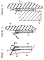
- Fig. 1 shows a known section of adhesive film, as it is called Power Strips "® is commercially available.
- This consists of an adhesive 1 with a handle 2, namely covers arranged on both sides at one end of the adhesive 1, and a cover paper 3 on each of the two sides of the adhesive 1. Pull the cover paper 3 in One side of the adhesive mass 1 is exposed in the direction of arrow A. With this adhesive side, the adhesive film section can be glued to a substrate, for example a wall 4, as shown in Fig. 2.
- the other cover paper 3 can be in the direction of arrow B, and the adhesive side underneath is exposed, an object 5 can be glued to it so that the handle 2 protrudes from the adhesive joint, a firm, resilient and permanent bond is achieved, but this can be done by pulling on the handle 3 can be removed again without leaving any residue in the direction of arrow C, as shown in Fig. 3. Only object 5 is to be held or secured so that it ultimately does not falls down and breaks.
- FIG. 4 shows a known section of adhesive film made of adhesive 1, handle 2 and cover paper 3, from which one cover paper according to the section explained in FIG. 1 has already been removed. With the side on which the adhesive 1 is exposed, the adhesive film section is glued to a plate 6. This plate 6 has a slot 7, which remains free. 5 shows how the cover paper 3 can be removed in the direction of the arrow D, in order to then in turn glue this adhesive bond to an object 5, FIG. 6.
- This bond can now be suspended or fastened via the slotted hole 7, somewhat by pulling a cord through the slotted hole 7 to hang the bond thereon, or by connecting the bond via the Slotted hole 7 is pushed onto the head of a hammered nail, screw or the like and hung on it.
- This ensures a firm bond that can be hung reliably even with a weighty object 5, without even a part of the adhesive arrangement being visible.
- a residue-free, damage-free separation of the composite is possible by first detaching the composite and then pulling on the handle 2 in the direction of arrow E.
- the object 5 remains undamaged, as does the plate 6, which can be used together with a fresh section of adhesive film.
- FIG. 7 A further embodiment is shown in FIG. 7, according to which an adhesive film section with adhesive 1, handle 2 and cover paper 3 is glued to a hook plate 8, according to DE 42 33 872 C.
- the hook plate 8 has a protruding hook 9 , which fits into the slotted hole 7 in a plate 6 (FIG. 4), the hook 9 first being inserted into the hole of the slotted hole 7 and then with its thinner part of the hook 9 being slidable into the slotted part of the slotted hole 7, so that the Hook 9 is thus secured against unwanted pulling out of the slot 7.
- the cover 3 is pulled off this adhesive bond in the direction of the arrow F and the adhesive bond is now bonded to a wall or the like, as shown in FIG. 8.
- FIG. 8 A pre-assembled composite of object 5 with an adhesive film section made of adhesive 1 and handle 2 and an affixed plate 6 with a slotted hole 7 can be attached to the pre-assembled hook plate 8 according to FIG. 8, initially in the direction of arrow J. In Conversely, this connector can also be released again.
- Fig. 9 the assembly so assembled is shown suspended on the wall 4, the manner of attachment and suspension not being visible, but being separable for all parts without damage and without residue, the hook plate 8 and the plate 6 being able to be used again .
- Suitable materials for the plate 6 and the counter bracket, such as the hook plate 8 are plastic (transparent or opaque; polyolefins, such as PE, PP, PS; polyester; PMMA; polycarbonate; PVC; formica, etc.; likewise wood and lacquered wood or glass and metal.
- the use according to the invention can be such that a fastening device, such as an eyelet or a slotted hole 7 of a plate 6 for fastening a cord or the like protrudes above the object to be fastened, but in particular this plate 6 can hidden ".
- a fastening device such as an eyelet or a slotted hole 7 of a plate 6 for fastening a cord or the like protrudes above the object to be fastened, but in particular this plate 6 can hidden ".
- a painted glass plate of rectangular shape (dimensions 18cm x 12cm) is provided with two eyelets on the back, which allows it to be fixed using two nylon cords attached to it.
- the adhesive eyelets each consist of a rectangular 0.8mm thick PMMA strip measuring 65mm x 25mm. At one end, the PMMA strips have a perforation, which is 12.5 mm centered from the sides and one end of the PMMA strip.
- the PMMA strips also have an integrated adhesive film measuring 50mm x 20mm.
- the adhesive film is attached to the side opposite the perforated end of the PMMA strip in such a way that the handle (14mm x 20mm) lies opposite the perforated side of the PMMA strip and extends 10mm above its lower edge.
- the adhesive film is covered with an adhesive release paper (see FIG. 4).
- the release papers are removed from two adhesive eyelets. Then the glue eyelets are glued to the left and right on the back of the glass plates in such a way that the perforation comes to lie approx. 10 mm above the upper edge of the glass plate.
- the painted glass plate can easily be attached to a metal hook attached to a wall using two nylon threads.
- the glass plate In order to remove the adhesive eyelets from the back of the glass plate without leaving any residue, the glass plate is removed from the wall and the adhesive film is pulled out starting from the handle strip by pulling it out parallel to the bonding plane. If a new adhesive tape is available, the base of the adhesive eyelet can be reused.
- a brass plate of ellipsoidal shape with the dimensions 30cm (maximum diameter) x 18cm (minimum diameter) is provided with an adhesive eyelet according to Example 1 so that it is completely hidden behind the brass plate.
- the brass plate can be attached to a hook in a wall, which is located above the brass plate, using a nylon strap.
- the procedure for removing the adhesive eyelets from the brass plate is as in Example 1.
- the brass plate from Example 2 is attached directly to the hook on the wall via the perforation of the adhesive eyelet. Both the glue eyelet and the hook in the wall remain invisible behind the brass plate.
Landscapes
- Chemical & Material Sciences (AREA)
- Organic Chemistry (AREA)
- Adhesive Tapes (AREA)
- Adhesives Or Adhesive Processes (AREA)
- Mirrors, Picture Frames, Photograph Stands, And Related Fastening Devices (AREA)
- Processing Of Solid Wastes (AREA)
- Packaging Of Machine Parts And Wound Products (AREA)
- Hooks, Suction Cups, And Attachment By Adhesive Means (AREA)
- Supports Or Holders For Household Use (AREA)
Abstract
Description
- Die Erfindung betrifft die Verwendung eines Klebfolien-Abschnittes für eine rückstandsfreie und beschädigungslos wiederablösbare Verklebung, sowie entsprechende Klebeverbunde.
- Klebfolien, die durch Ziehen in der Verklebungsebene wiederablösbar sind, sind bekannt und im Handel erhältlich, so als
 Power Strips" ® von der, Beiersdorf AG.
 - So beschreibt US 4,024,312 ein Selbstklebeband mit einem dehnbaren und elastischen Träger aus einem Blockcopolymeren, insbesondere für Anwendungen im medizinischen Bereich, wo ein schmerzloses Abziehen von der Haut erwünscht ist.
- Weiterhin beschreibt DE 33 31 016 A1 eine Klebfolie für wiederlösbare Klebbindungen, die es gestattet, daß eine damit hergestellte Klebbindung durch Ziehen an der Klebfolie in Richtung der Verklebungsebene lösbar ist. Mit solchen Klebfolie lassen sich hohe Klebkräfte und Scherfestigkeiten erzielen und Klebverbunde ohne weitere Hilfsmittel wieder lösen, vergleichbar dem Öffnen eines Weckglases, ähnlich wie dort die Gummidichtung am Anfasser aus der Dichtungsfuge gezogen wird.
- Ferner beschreibt DE 37 144 53 C1 einen zerstörungsfrei von Übungsobjekten wieder abnehmbaren Übungssprengkörper, der mit solch einer Klebfolie reversibel befestigt wird.
- Auch WO 92/11333 beschreibt unter anderem Klebfolien für entsprechende Anwendungen, wobei die eingesetzten Klebfolien eine geringe Elastizität bei gleichzeitig hoher Dehnung aufweisen.
- DE 42 22 849 C1 beschreibt ebenfalls einen Streifen einer Klebfolie dieser Art mit einem besonders ausgestalteten Anfasser.
- Schließlich beschreiben DE 42 33 872 C2 und WO 94/21157 wiederablösbare selbstklebende Haken, die ebenfalls mit derartigen Klebfolien ausgerüstet und also wiederablösbar sind.
- Die in den vorgenannten Druckschriften dargestellten Klebstoffsysteme weisen jedoch auch eine Anzahl von Nachteilen auf:
- Um die Klebfolie aus der Klebfuge herauslösen zu können, muß ein Teil derselben in Form eines Anfassers aus dieser hervortreten. Die Klebfolie ist damit notwendigerweise bei der Verklebung nicht flexibler Gegenstände nicht völlig unsichtbar, sondern der Anfasser ist sichtbar, welches optisch unvorteilhaft erscheinen kann und bei Verwendung von Materialien, welche unter Lichteinfluß altern, auch zu technischen Problemen führen kann.
- Beim Verkleben kann es leicht dazu kommen, daß die gesamte Klebfolie, also inklusive Anfasser, in der Klebfuge verschwindet. Besonders dem Laien kann dies passieren, wenn er einen Abschnitt einer solchen Klebfolie nicht so am Rande des Substrates plaziert, daß ein Anfasser übersteht und dann aus der Klebfuge herausragt. Beim Lösen der Verklebung ist dann guter Rat teuer und ein Zerstören zumindest des einen Substrates kann die Folge sein.
- Tritt ein Reißen der Klebfolien beim Ablöseprozeß auf und verbleibt ein gerissener Klebfolienteil vollständig in der Klebfuge, so ist eine rückstandsfreie Trennung der verklebten Materialien ohne Zerstörung der Verklebungspartner zumeist nicht mehr möglich, welches einen erheblichen Schaden verursachen kann.
- So bleibt es ein ungelöstes Problem, wie denn wertvolle oder solche Gegenstände, die unbeschädigt bleiben sollen, insbesondere nicht angebohrt werden sollen, reversibel, rückstandsfrei wiederlösbar und beschädigungslos zu befestigen seien. Etwa eine Kinder-Glasmalerei soll vorübergehen aufgehängt werden, eine dekorative Kachel, oder aber auch noch schwerere Gegenstände, und zwar möglichst ohne sichtbare Anfasser oder dergleichen überstehende oder aus der Klebfuge herausragende Fremdkörper. Aufgabe der Erfindung war es, hier Abhilfe zu schaffen.
- Demgemäß betrifft die Erfindung die Verwendung von eingangs beschriebenen Klebfolien-abschnitten, wie dies in den Patentansprüchen näher gekennzeichnet ist, ebenso die dort näher gekennzeichneten Klebverbunde.
- Bezüglich der einzusetzenden Klebfolien-Abschnitte wird auf den zitierten Stand der Technik verwiesen.
- Die Ablösung der verklebten Gegenstände wird dabei durch die Dehnung des doppelseitigen Haftklebebandes erreicht. Der auftretende Adhäsionsverlust wird durch Verringerung der Klebrigkeit der Haftklebemasse analog DE 33 31 016 bzw. DE 42 22 849 begünstigt, sowie durch die Reduktion der Klebfoliendicke, verursacht durch die Dehnung der Klebstoff-Folie.
- Bei Verwendung von Klebfolien-Abschnitten mit einem Zwischenträger kommen insbesondere Produkte vom Typus wie in WO 92/11333 in Betracht.
- Die Erzeugungsmöglichkeit der nicht haftklebrigen Bereiche für Anfasser sind vielfältig. Sie kann z.B. durch Inertisierung der Haftklebemasse mittels eines nicht klebrigen Lackes erfolgen. Weitere Möglichkeiten umfassen das Zukaschieren von dünnen Schichtmaterialien wie Kunststoff-Folien und Papieren.
- Als Deckpapier oder Trennlaminate eignen sich die übliche Trennfolien und Trennpapiere, z.B. silikonisierte Trennfolien/Trennpapiere, welche üblicherweise als gut trennende flächige Medien gegenüber Haftklebemassen eingesetzt werden.
- Generell sei zu Herstellung, Verarbeitung und Handhabung von den besonders bevorzugten Klebfolien auf DE 33 31 016, DE 42 22 849 und WO 92/11333 verwiesen.
- In den folgenden Beispielen soll die Erfindung anhand von Ausführungsbeispielen beschrieben werden, ohne sie damit unnötig einschränken zu wollen.
- Es zeigen:
- Fig. 1-3
- einen vorbekannten Klebeverbund
- Fig. 4
- eine Platte, wie sie erfindungsgemäß mit einem Klebfolien-Abschnitt ausgerüstet verwendet wird
- Fig. 5
- einen Klebverbund gemäß Fig. 4, schematisch seitlich
- Fig. 6
- einen Gegenstand, ausgerüstet mit einem Klebverbund gemäß Fig. 5, schematisch seitlich
- Fig. 7
- eine Hakenplatte, schematisch seitlich, die gemäß
- Fig. 8
- an einer Wand angeklebt und mit einem ausgerüsteten Gegenstand gemäß Fig. 6 zusammengebracht wird, schematisch seitlich, und
- Fig. 9
- einen fertigen derartigen Verbund, ebenfalls schematisch seitlich.
- Fig. 1 zeigt einen bekannten Klebfolien-Abschnitt, wie er unter der BezeichnungPower Strips" ® im Handel ist. Dieser besteht aus einer Klebmasse 1 mit einem Anfasser 2, nämlich beiderseits am einen Ende der Klebmasse 1 angeordneten Abdeckungen, sowie jeweils einem Deckpapier 3 auf den beiden Seiten der Klebemasse 1. Zieht man das eine Deckpapier 3 in Richtung des Pfeiles A ab, so liegt die eine Seite der Klebmasse 1 frei. Mit dieser Klebseite kann der Klebfolien-Abschnitt auf einen Untergrund, etwa eine Wand 4 aufgeklebt werden, wie in Fig. 2 dargestellt. Nun kann das andere Deckpapier 3 in Richtung des Pfeiles B abgezogen werden, und die darunter befindliche Klebseite liegt frei. Auf ihr kann ein Gegenstand 5 so angeklebt werden, daß der Anfasser 2 aus der Klebfuge hervorsteht. Eine feste, belastbare und dauerhafte Verklebung ist erreicht, die jedoch durch Ziehen an dem Anfasser 2 in Richtung des Pfeiles C, wie in Fig. 3 dargestellt, rückstandsfrei wieder lösbar ist. Lediglich der Gegenstand 5 ist festzuhalten oder zu sichern, damit er schlußendlich nicht herabfällt und kaputt geht.
- Das in Fig. 1 bis 3 Dargestellte ist Stand der Technik.
- Fig. 4 und folgende zeigen demgegenüber erfindungsgemäße Ausführungsformen. So ist in
Fig. 4 zunächst wiederum ein bekannter Klebfolien-Abschnitt aus Klebmasse 1, Anfasser 2 und Deckpapier 3 dargestellt, von dem das eine Deckpapier gemäß dem in Fig. 1 erläuterten Abschnitt bereits abgezogen ist. Mit der Seite, auf der also die Klebmasse 1 freiliegt, wird der Klebfolien-Abschnitt auf eine Platte 6 geklebt. Diese Platte 6 weist ein Schlitzloch 7 auf, das dabei frei bleibt. In der Seitenansicht dieses Klebeverbundes gemäß Fig. 5 ist dargestellt, wie das Deckpapier 3 in Richtung des Pfeiles D abgezogen werden kann, um dann diesen Klebverbund seinerseits auf einen Gegenstand 5 aufzukleben, Fig. 6. Diesen Verbund kann man nun über das Schlitzloch 7 aufhängen oder befestigen, etwas indem eine Schnur durch das Schlitzloch 7 gezogen wird, um daran den Verbund aufzuhängen, oder indem etwa der Verbund über das Schlitzloch 7 auf den Kopf eines eingeschlagenen Nagels, einer Schraube oder dergleichen geschoben und daran aufgehängt wird. Damit ist ein fester Verbund gewährleistet, der auch bei gewichtigem Gegenstand 5 zuverlässig aufgehängt werden kann, ohne daß dabei auch nur ein Teil der Klebanordnung zu sehen wäre. Zudem ist ein rückstandsfreies, beschädigungsloses Trennen des Verbundes möglich, indem der Verbund zunächst wieder abgehängt wird und dann am Anfasser 2 in Richtung des Pfeiles E gezogen wird. Dabei bleibt der Gegenstand 5 unbeschädigt zurück, ebenso die Platte 6, die mit einem frischen Klebfolien-Abschnitt zusammen erneut verwendet werden kann. - Eine weitere Ausgestaltung ist in Fig. 7 folgende dargestellt, gemäß der ein Klebfolien-Abschnitt mit Klebmasse 1, Anfasser 2 und Deckpapier 3 auf eine Hakenplatte 8 aufgeklebt ist., gemäß DE 42 33 872 C. Die Hakenplatte 8 weist einen vorstehenden Haken 9 auf, der in das Schlitzloch 7 in einer Platte 6 (Fig. 4) paßt, wobei zunächst der Haken 9 in das Loch des Schlitzlochs 7 eingeführt und dann mit seinem dünneren Teil des Hakens 9 in den Schlitzteil des Schlitzlochs 7 schiebbar ist, so daß der Haken 9 damit gegen ein ungewolltes Herausziehen aus dem Schlitzloch 7 gesichert ist. Von diesem Klebverbund wird die Abdeckung 3 in Richtung des Pfeils F abgezogen und der Klebverbund wird nun auf eine Wand oder dergleichen geklebt, wie dies in Fig. 8 dargestellt ist. Dort sitzt er fest und stark belastbar, ist jedoch bei Bedarf leicht und rückstandsfrei wieder ablösbar, indem man an dem vorstehenden Anfasser 2 in Richtung des Pfeils G zieht. Die Hakenplatte 8 ist danach wieder verwendbar und kann mit einem neuen Klebfolien-Abschnitt ausgerüstet und eingesetzt werden. Auf die vormontierte Hakenplatte 8 gemäß Fig. 8 läßt sich nun ein gemäß Fig. 6 vormontierter Verbund aus Gegenstand 5 mit aufgeklebtem Klebfolien-Abschnitt aus Klebmasse 1 und Anfasser 2 und darauf aufgeklebter Platte 6 mit Schlitzloch 7 aufstecken, zunächst in Richtung des Pfeils J. In umgekehrter Weise ist diese Steckverbindung auch wieder lösbar. In Fig. 9 ist der so zusammengesteckte Verbund aufgehängt an der Wand 4 dargestellt, wobei die Art und Weise der Befestigung und Aufhängung nicht sichtbar, gleichwohl beschädigungslos und rückstandsfrei für alle Teile trennbar ist, wobei die Hakenplatte 8 und die Platte 6 erneut verwendet werden können.
- Geeignete Materialien für die Platte 6 und die Gegenhalterung, wie die Hakenplatte 8, sind Kunststoff (transparent oder undurchsichtig; Polyolefine, wie PE, PP, PS; Polyester; PMMA; Polycarbonat; PVC; Resopal etc.; ebenso Holz und lackiertes Holz oder Glas und Metall.
- Die erfindungsgemäße Verwendung kann so erfolgen, daß eine Vorrichtung zum Befestigen, wie etwa eine Öse oder ein Schlitzloch 7 einer Platte 6 zum Befestigen einer Schnur oder dergleichen oberhalb des zu befestigenden Gegenstandes herausragt, insbesondere kann diese Platte 6 aberverdeckt" angeklebt werden.
- Eine bemalte Glasplatte von rechteckiger Form (Abmessungen 18cm x 12cm) wird rückseitig mit zwei Klebeösen versehen, welche eine Fixierung selbiger über zwei daran befestigte Nylonschnüre erlaubt.
- Die Klebeösen bestehen aus je einem rechteckigen 0,8mm dicken PMMA-Streifen der Abmessungen 65mm x 25mm. An einem Ende verfügen die PMMA-Streifen über eine Lochung, welche jeweils 12,5mm mit ihrem Zentrum von den Seiten und einem Ende des PMMA-Streifens entfernt ist. Die PMMA-Streifen verfügen ferner über eine integrierte Klebfolie der Abmessungen 50mm x 20mm. Die Klebfolie ist derart auf die dem gelochten Ende des PMMA-Streifens gegenüber liegenden Seite befestigt, daß der Anfasser (14mm x 20mm) der gelochten Seite des PMMA-Streifens gegenüber liegt und 10mm über dessen Unterkante herausreicht. Die Klebfolie ist mit einem abhäsiv ausgerüsteten Trennpapier abgedeckt (vgl. Fig. 4). Verwendet werden hier und in den folgenden BeispielenPower Strips" ® der Beiersdorf AG, Hamburg.
- Zur Applikation der Klebeösen auf die Glasplatte werden von zwei Klebeösen die Trennpapiere abgelöst. Danach werden die Klebeösen derart links und rechts auf der Rückseite der Glasplatten verklebt, daß die Lochung ca. 10mm oberhalb der Oberkante der Glasplatte zu liegen kommt.
- Mittels vorgenannter Klebeösen läßt sich die bemalte Glasplatte leicht über zwei Nylonfäden an einem an einer Wand befestigten Metallhaken befestigen.
- Zum rückstandsfreien Entfernen der Klebeösen von der Rückseite der Glasplatte wird die Glasplatte von der Wand abgenommen und die Klebfolie ausgehend vom Anfasserstreifen durch Herausziehen parallel zur Verklebungsebene herausgezogen. Steht ein neuer Klebstreifen zur Verfügung, so kann der Klebeösenbasiskörper wiederverwendet werden.
- Eine Messingplatte von ellipsoider Form der Abmessungen 30cm (maximaler Durchmesser) x 18cm (minimaler Durchmesser) wird derart mit einer Klebeöse entsprechend Beispiel 1 versehen, daß diese komplett hinter der Messingplatte verdeckt angebracht werden. Über ein Nylonband läßt sich die Messingplatte an einen in einer Wand applizierten Haken befestigen, welcher sich oberhalb der Messingplatte befindet. Zum Lösen der Klebeösen von der Messingplatte verfährt man wie in Beispiel 1.
- Die Messingplatte aus Beispiel 2 wird direkt über die Lochung der Klebeöse auf einem in der Wand befindlichen Haken befestigt. Hierbei bleiben sowohl die Klebeöse als auch der in der Wand befindliche Haken unsichtbar hinter der Messingplatte.
Claims (10)
- Verwendung eines Klebfolien-Abschnittes für eine rückstandsfreie und beschädigungslos wiederablösbare Verklebunga) einer Platte (6) an einem zu fixierenden oder aufzuhängenden Gegenstand (5) mittels b) einer doppelseitig klebenden Klebfolie (1) mit einem aus der Klebfuge herausragenden Anfasser (2), an dem durch Ziehen in Richtung der Verklebungsebene die Verklebung lösbar ist, wobeic) die Platte (6) eine Vorrichtung (7) aufweist, an der eine Fixierung oder Aufhängung in an sich bekannter Weise ansetzen kann, und wobeid) die Verklebung für den Betrachter des so fixierten oder aufgehängten Gegenstandes (5), gegebenenfalls durch den Gegenstand (5) selbst, verdeckt erfolgt.
- Verwendung eines Klebfolien-Abschnittes für eine rückstandsfreie und beschädigungslos wiederablösbare Verklebung nach Anspruch 1, dadurch gekennzeichnet, daß der Klebfolien-Abschnitt mit oder ohne Zwischenträger elastisch oder plastisch dehnbar ist.
- Verwendung eines Klebfolien-Abschnittes für eine rückstandsfreie und beschädigungslos wiederablösbare Verklebung nach Anspruch 1, dadurch gekennzeichnet, daß die Adhäsion des Klebfolien-Abschnittes geringer als die Kohäsion ist, das Haftvermögen beim Dehnen weitgehend verschwindet und das Verhältnis von Abzugskraft zu Reißlast mindestens 1 : 1,5 ist.
- Verwendung eines Klebfolien-Abschnittes für eine rückstandsfreie und beschädigungslos wiederablösbare Verklebung nach Anspruch 1, dadurch gekennzeichnet, daß der Klebfolien-Abschnitt ein solcher auf Basis von thermoplastischem Kautschuk und klebrigmachenden Harzen ist, mit hoher Elastizität und geringer Plastizität.
- Verwendung eines Klebfolien-Abschnittes für eine rückstandsfreie und beschädigungslos wiederablösbare Verklebung nach Anspruch 1, dadurch gekennzeichnet, daß die Platte (6) flach ausgestaltet ist und in ihrem oberen Bereich eine Öse oder ein Schlitzloch aufweist.
- Verwendung eines Klebfolien-Abschnittes für eine rückstandsfreie und beschädigungslos wiederablösbare Verklebung nach Anspruch 1, dadurch gekennzeichnet, daß die Platte (6) flach ausgebildet ist und in ihrem oberen Bereich einen Haken aufweist.
- Verwendung eines Klebfolien-Abschnittes für eine rückstandsfreie und beschädigungslos wiederablösbare Verklebung nach Anspruch 1, dadurch gekennzeichnet, daß die Fixierung oder Aufhängung mittels der Vorrichtung (Öse, Schlitzloch) (7) an der Platte (6) an einer Gegenhalterung (8) erfolgt, mit einer daran befindlichen und der Vorrichtung (Öse, Schlitzloch) (7) entsprechenden Ausgestaltung (9), wobei die Gegenhalterung (8) gegebenenfalls ihrerseits mittels eines Klebfolien-Abschnittes gemäß Anspruch 1 wiederlösbar befestigt ist.
- Verwendung eines Klebfolien-Abschnittes für eine rückstandsfreie und beschädigungslos wiederablösbare Verklebung nach Anspruch 1, dadurch gekennzeichnet, daß die Platte (6) und gegebenenfalls die Gegenhalterung (8) wiederverwendbar sind.
- Klebfolien-Abschnitt mit Platte (6) gemäß einem der Ansprüche 1 bis 6 und 8.
- Klebfolien-Abschnitt mit Platte (6) und Gegenhalterung (8) gemäß einem der Ansprüche 7 und 8.
Applications Claiming Priority (2)
| Application Number | Priority Date | Filing Date | Title |
|---|---|---|---|
| DE19511288A DE19511288C2 (de) | 1995-03-28 | 1995-03-28 | Verwendung eines doppelseitig klebenden Klebfolien-Abschnittes für eine Fixierung oder Aufhängung eines Gegenstandes |
| DE19511288 | 1995-03-28 |
Publications (3)
| Publication Number | Publication Date |
|---|---|
| EP0735121A2 true EP0735121A2 (de) | 1996-10-02 |
| EP0735121A3 EP0735121A3 (de) | 1997-07-02 |
| EP0735121B1 EP0735121B1 (de) | 2001-05-23 |
Family
ID=7757925
Family Applications (1)
| Application Number | Title | Priority Date | Filing Date |
|---|---|---|---|
| EP96103551A Expired - Lifetime EP0735121B1 (de) | 1995-03-28 | 1996-03-07 | Verfahren zum verdeckten Verkleben mittels eines Klebfolien-Abschnitts für eine rückstandsfreie und beschädigungslose wiederablösbare Verklebung |
Country Status (8)
| Country | Link |
|---|---|
| US (2) | US6245177B1 (de) |
| EP (1) | EP0735121B1 (de) |
| JP (1) | JPH08269403A (de) |
| AT (1) | ATE201435T1 (de) |
| DE (2) | DE19511288C2 (de) |
| DK (1) | DK0735121T3 (de) |
| ES (1) | ES2158170T3 (de) |
| PT (1) | PT735121E (de) |
Cited By (12)
| Publication number | Priority date | Publication date | Assignee | Title |
|---|---|---|---|---|
| EP0845514A2 (de) * | 1996-11-30 | 1998-06-03 | Beiersdorf Aktiengesellschaft | Klebeband |
| EP0845513A2 (de) * | 1996-11-30 | 1998-06-03 | Beiersdorf Aktiengesellschaft | Klebeband |
| EP0845517A2 (de) * | 1996-12-02 | 1998-06-03 | Beiersdorf Aktiengesellschaft | Verwendung eines Klebeband-Abschnitts |
| EP0845515A2 (de) * | 1996-11-30 | 1998-06-03 | Beiersdorf Aktiengesellschaft | Klebeband |
| EP1111020A2 (de) | 1999-12-22 | 2001-06-27 | Henkel Kommanditgesellschaft auf Aktien | Lösbare Klebeverbindungen |
| US6855760B1 (en) | 1999-05-26 | 2005-02-15 | Henkel Kommanditgesellschaft Auf Aktien | Detachable adhesive compounds |
| US7101615B2 (en) * | 1997-05-14 | 2006-09-05 | Tesa Ag | Double-sided adhesive tape and its use |
| US7147742B2 (en) | 2000-08-03 | 2006-12-12 | Henkel Kommanditgesellschaft Auf Aktien ( Henkel Kgaa) | Method for accelerating the curing of adhesives |
| EP1170344B1 (de) * | 2000-07-08 | 2007-05-16 | tesa AG | Kunststoffteil |
| US7273580B2 (en) | 2000-08-03 | 2007-09-25 | Henkel Kommanditgesellschaft Auf Aktien (Henkel Kgaa) | Ferromagnetic resonance excitation and its use for heating substrates that are filled with particles |
| US7407704B2 (en) | 1999-10-27 | 2008-08-05 | Henkel Kgaa | Process for adhesive separation of bonded joints |
| EP3885404A1 (de) | 2020-03-23 | 2021-09-29 | Covestro Deutschland AG | Verwendung von mischungen ätherischer öle zur auftrennung von klebungen |
Families Citing this family (72)
| Publication number | Priority date | Publication date | Assignee | Title |
|---|---|---|---|---|
| US5516581A (en) * | 1990-12-20 | 1996-05-14 | Minnesota Mining And Manufacturing Company | Removable adhesive tape |
| DE19632182B4 (de) * | 1996-08-09 | 2004-07-29 | Tesa Ag | Verwendung eines Klebfolien-Abschnittes für eine rückstandsfreie und beschädigungslos wiederablösbare Verklebung mit Platte und Adaptervorrichtung |
| DE19708364A1 (de) * | 1997-03-01 | 1998-09-03 | Beiersdorf Ag | Haltevorrichtung |
| EP0885571B1 (de) * | 1997-06-21 | 2003-08-27 | Tesa AG | Klebfolienstreifen-Verbund und seine Verwendung |
| DE19735229A1 (de) | 1997-08-14 | 1999-02-18 | Beiersdorf Ag | Haltevorrichtung |
| DE19735234A1 (de) | 1997-08-14 | 1999-02-18 | Beiersdorf Ag | Haltevorrichtung |
| DE19735228A1 (de) | 1997-08-14 | 1999-02-18 | Beiersdorf Ag | Haltevorrichtung |
| DE19820655A1 (de) * | 1998-05-08 | 1999-11-18 | Johannes Rueckel | Befestigungsvorrichtung zum Befestigen eines Gegenstandes auf einer Unterlage |
| DE10029627C2 (de) * | 1999-06-24 | 2001-11-08 | Henkel Kgaa | Verfahren und Flächengebilde zum lösbaren Befestigen eines Gegenstands an einer Fläche |
| DE19956946B8 (de) | 1999-11-26 | 2005-01-20 | Tesa Ag | Verpackung für Klebfolien |
| DE10055942A1 (de) | 2000-11-10 | 2002-06-06 | Tesa Ag | Haftklebemasse und ihre Verwendung |
| DE10063854A1 (de) | 2000-12-21 | 2002-09-05 | Tesa Ag | Wiederablösbare Vorrichtung |
| DE10064160A1 (de) | 2000-12-22 | 2002-08-14 | Tesa Ag | Klebfolienstreifen |
| DE10129608A1 (de) | 2001-06-20 | 2003-05-28 | Tesa Ag | Stripfähige Systeme auf Basis von Acrylatblockcopolymeren |
| DE10205761B4 (de) * | 2002-02-12 | 2010-02-04 | Fujitsu Siemens Computers Gmbh | Anordnung zum Befestigen einer Komponente an einem Gehäuse mittels einer Klebeverbindung |
| DE10207935A1 (de) | 2002-02-23 | 2003-09-04 | Tesa Ag | Befestigungsmittel |
| DE10212049A1 (de) | 2002-03-19 | 2003-10-02 | Tesa Ag | Haftklebemasse und Verfahren zur Herstellung hierzu |
| DE10236547A1 (de) * | 2002-08-08 | 2004-02-19 | Tesa Ag | Zumindest zweiteilige Haltevorrichtung |
| US20040084598A1 (en) * | 2002-11-01 | 2004-05-06 | Dodig John M. | Method and apparatus for hanging pictures and other wall objects |
| US20040140413A1 (en) * | 2002-11-01 | 2004-07-22 | Dodig John M. | Method and apparatus for hanging pictures and other wall |
| US7216841B2 (en) * | 2002-11-01 | 2007-05-15 | Dodig Jr John M | Method and apparatus for hanging pictures and other wall objects |
| DE10252089A1 (de) | 2002-11-08 | 2004-05-27 | Tesa Ag | Klebemasse und Verwendung derselben für einen Haftklebfolienstreifen aus mindestens einer Schicht, der sich durch dehnendes Verstrecken im wesentlichen in der Verklebungsebene rückstands- und zerstörungsfrei wieder ablösen lässt |
| WO2004071310A1 (en) * | 2003-02-10 | 2004-08-26 | Smith & Nephew, Inc. | Acetabular reamer |
| US7784762B2 (en) * | 2005-12-06 | 2010-08-31 | Fermions, L.L.C. | Wall hanging mounting device |
| DE10328468B4 (de) * | 2003-06-25 | 2017-06-08 | Kronowetter Kunststoff- Und Metalltechnik Gmbh | Spiegelklebeplatte zur Befestigung eines Innenspiegels an einer Fensterscheibe eines Kraftfahrzeugs |
| CA2490567A1 (en) * | 2003-12-22 | 2005-06-22 | Crant Corporation | Wall covering system and mounting member therefor |
| DE10361540A1 (de) * | 2003-12-23 | 2005-07-28 | Tesa Ag | Chemisch vernetzbare, durch Zug in Richtung der Verklebungsebene lösbare Klebestreifen |
| US20070096003A1 (en) * | 2005-11-03 | 2007-05-03 | Kuo Liao Hsiu-Mei | Sticker type wall surface holder |
| US7506450B2 (en) * | 2006-06-30 | 2009-03-24 | The Stanley Works | Adhesive mount for a leveling device and a leveling device |
| DE102006038719A1 (de) | 2006-08-18 | 2008-02-21 | Tesa Ag | Haftklebestreifen für feuchtigkeitsunempfindliche wiederablösbare Verklebungen |
| US7441741B2 (en) * | 2006-09-22 | 2008-10-28 | Hammond Wong | Hanger apparatus and method |
| US20090101778A1 (en) * | 2007-06-20 | 2009-04-23 | Fermions, L.L.C. | Wall hanging mounting device |
| US8209836B2 (en) * | 2007-06-20 | 2012-07-03 | Todd A. Rathe | Wall support mounting device |
| DE102007032641A1 (de) | 2007-07-11 | 2009-01-15 | Tesa Ag | Adaptersystem zur lösbaren Befestigung von Gegenständen |
| US20090071097A1 (en) * | 2007-09-19 | 2009-03-19 | Mcdonald Raiford | Wall covering product and method of using same |
| US8973878B2 (en) * | 2008-03-27 | 2015-03-10 | 3M Innovative Properties Company | Surface mount systems and methods |
| US7676946B2 (en) * | 2008-04-15 | 2010-03-16 | Brian Lee Page | Invisible mounting system |
| DE102008033322A1 (de) * | 2008-07-16 | 2010-01-21 | Tesa Se | Verfahren und Verwendung von Klebestreifen zur Abdeckung oder Versiegelung optisch hochwertiger Oberflächen |
| US9922582B1 (en) * | 2008-09-24 | 2018-03-20 | Robert Edward Rock | Wall mounting apparatus |
| US8468770B2 (en) | 2009-09-23 | 2013-06-25 | Textile Rubber & Chemical Company, Inc. | Floor covering product and method of using same |
| US8851440B2 (en) | 2010-09-29 | 2014-10-07 | Velcro Industries B.V. | Releasable hanging system |
| US8814112B2 (en) | 2010-12-20 | 2014-08-26 | 3M Innovative Properties Company | Article support device comprising a rotatable connection |
| US8430371B2 (en) * | 2011-09-02 | 2013-04-30 | Steven G. Boelstler | Quick release hook and loop device |
| US8979054B2 (en) | 2012-12-17 | 2015-03-17 | 3M Innovative Properties Company | Wall mountable storage assembly with articulating connection |
| DE202013012788U1 (de) | 2012-12-19 | 2019-08-29 | Tesa Se | Wiederablösbarer Haftklebestreifen |
| DE102012223670A1 (de) | 2012-12-19 | 2014-06-26 | Tesa Se | Wiederablösbarer Haftklebestreifen |
| CN103887451A (zh) * | 2012-12-22 | 2014-06-25 | 富泰华工业(深圳)有限公司 | 电池固定结构及具有电池固定结构的电子装置 |
| CN103996351B (zh) * | 2013-02-20 | 2020-01-21 | 泰科消防及安全有限公司 | 粘合剂结合的物品保护标签 |
| US10222580B2 (en) * | 2013-02-21 | 2019-03-05 | Plx, Inc. | Mounts for an optical structure having a grooved protruding member with a damping ring disposed in or on the groove and methods of mounting an optical structure using such mounts |
| DE102013206624A1 (de) | 2013-04-15 | 2014-10-16 | Tesa Se | Haftklebemasse und Verwendung derselben in einem Haftklebstreifen |
| US9554674B2 (en) | 2013-10-08 | 2017-01-31 | Liberty Hardware Mfg. Corp. | Shower rod mounting assembly |
| US20150204376A1 (en) * | 2014-01-22 | 2015-07-23 | Ccl Label, Inc. | Device for hanging items on a vertical surface and method for making and using same |
| US10925417B2 (en) | 2014-01-22 | 2021-02-23 | Ccl Label, Inc. | Secure hold hook |
| DE102014208263A1 (de) | 2014-04-30 | 2015-11-05 | Tesa Se | Ablösehilfe für eine wiederablösbare Klebefolie |
| DE102014208264A1 (de) | 2014-04-30 | 2015-11-05 | Tesa Se | Hilfsklebeband für eine wiederablösbare Klebefolie |
| EP3581630B1 (de) | 2015-04-02 | 2021-07-14 | tesa SE | Wiederablösbarer haftklebestreifen |
| DE102015206076A1 (de) | 2015-04-02 | 2016-10-06 | Tesa Se | Wiederablösbarer Haftklebestreifen |
| DE202015009721U1 (de) | 2015-04-02 | 2019-08-23 | Tesa Se | Wiederablösbarer Haftklebestreifen |
| DE202015009730U1 (de) | 2015-04-02 | 2019-09-06 | Tesa Se | Wiederablösbarer Haftklebestreifen |
| DE202015009724U1 (de) | 2015-04-02 | 2019-08-16 | Tesa Se | Wiederablösbarer Haftklebestreifen |
| DE202015009141U1 (de) | 2015-10-15 | 2016-11-03 | Tesa Se | Klebemasse, insbesondere für stripbare Klebestreifen, und Verwendung zur Verklebung auf getrichener Raufasertapete |
| DE102015220072A1 (de) | 2015-10-15 | 2017-04-20 | Tesa Se | Selbstklebeartikel und dessen Verwendung zur Verklebung auf gestrichener Raufasertapete |
| DE102016205166A1 (de) | 2016-03-30 | 2017-10-05 | Tesa Se | Darreichungsform für doppelseitig wirksame Klebemittel |
| DE102016223852A1 (de) | 2016-11-30 | 2018-05-30 | Tesa Se | Wiederablösbarer Haftklebestreifen |
| DE102017203092A1 (de) | 2017-02-24 | 2018-08-30 | Tesa Se | Wiederablösbarer Haftklebestreifen |
| US10221883B2 (en) | 2017-04-07 | 2019-03-05 | Artskills, Inc. | Apparatus for supporting articles |
| DE102017206083A1 (de) | 2017-04-10 | 2018-10-11 | Tesa Se | Verklebung in elektrochemischen Zellen und Stapeln von elektrochemischen Zellen |
| CN107450206A (zh) * | 2017-09-06 | 2017-12-08 | 惠科股份有限公司 | 一种缓冲件及压合装置 |
| DE102017220998A1 (de) | 2017-11-23 | 2019-05-23 | Tesa Se | Wiederablösbarer Haftklebestreifen |
| DE102019204344A1 (de) | 2019-03-28 | 2020-10-01 | Tesa Se | Wiederablösbarer Haftklebestreifen |
| US11699865B2 (en) * | 2019-05-10 | 2023-07-11 | 3M Innovative Properties Company | Removable electrical connectors and devices |
| CA3212923A1 (en) | 2021-05-19 | 2022-11-24 | Jeffery L. Jackson | Methods and apparatus for non-destructive adhesive devices |
Citations (3)
| Publication number | Priority date | Publication date | Assignee | Title |
|---|---|---|---|---|
| WO1992011333A1 (en) * | 1990-12-20 | 1992-07-09 | Minnesota Mining And Manufacturing Company | Removable adhesive tape |
| DE4233872A1 (de) * | 1992-09-30 | 1994-03-31 | Beiersdorf Ag | Wiederablösbarer, selbstklebender Haken |
| WO1994021157A1 (en) * | 1993-03-23 | 1994-09-29 | Minnesota Mining And Manufacturing Company | Article support using stretch releasing adhesives |
Family Cites Families (5)
| Publication number | Priority date | Publication date | Assignee | Title |
|---|---|---|---|---|
| US4041575A (en) * | 1976-07-29 | 1977-08-16 | Elder Laboratories | Hook assemblage |
| US4228982A (en) * | 1979-02-12 | 1980-10-21 | Sellera Jose M | Hanging device for pictures |
| DE3331016A1 (de) * | 1983-04-06 | 1984-10-11 | Beiersdorf Ag, 2000 Hamburg | Klebfolie fuer wiederloesbare klebbindungen |
| DE4222849C2 (de) * | 1992-07-11 | 2000-02-10 | Beiersdorf Ag | Verwendung eines Streifens einer Klebefolie für wiederlösbare Verklebung |
| US5605313A (en) | 1995-07-17 | 1997-02-25 | Erickson; Donald L. | Vertical surface object hanger |
-
1995
- 1995-03-28 DE DE19511288A patent/DE19511288C2/de not_active Expired - Fee Related
-
1996
- 1996-03-07 AT AT96103551T patent/ATE201435T1/de not_active IP Right Cessation
- 1996-03-07 DK DK96103551T patent/DK0735121T3/da active
- 1996-03-07 PT PT96103551T patent/PT735121E/pt unknown
- 1996-03-07 EP EP96103551A patent/EP0735121B1/de not_active Expired - Lifetime
- 1996-03-07 ES ES96103551T patent/ES2158170T3/es not_active Expired - Lifetime
- 1996-03-07 DE DE59606933T patent/DE59606933D1/de not_active Expired - Lifetime
- 1996-03-21 JP JP8091991A patent/JPH08269403A/ja active Pending
-
1999
- 1999-02-04 US US09/244,903 patent/US6245177B1/en not_active Expired - Fee Related
-
2001
- 2001-04-30 US US09/845,993 patent/US6641892B2/en not_active Expired - Fee Related
Patent Citations (3)
| Publication number | Priority date | Publication date | Assignee | Title |
|---|---|---|---|---|
| WO1992011333A1 (en) * | 1990-12-20 | 1992-07-09 | Minnesota Mining And Manufacturing Company | Removable adhesive tape |
| DE4233872A1 (de) * | 1992-09-30 | 1994-03-31 | Beiersdorf Ag | Wiederablösbarer, selbstklebender Haken |
| WO1994021157A1 (en) * | 1993-03-23 | 1994-09-29 | Minnesota Mining And Manufacturing Company | Article support using stretch releasing adhesives |
Cited By (19)
| Publication number | Priority date | Publication date | Assignee | Title |
|---|---|---|---|---|
| EP0845514A3 (de) * | 1996-11-30 | 1999-02-17 | Beiersdorf Aktiengesellschaft | Klebeband |
| EP0845513A2 (de) * | 1996-11-30 | 1998-06-03 | Beiersdorf Aktiengesellschaft | Klebeband |
| EP0845515A2 (de) * | 1996-11-30 | 1998-06-03 | Beiersdorf Aktiengesellschaft | Klebeband |
| EP0845513A3 (de) * | 1996-11-30 | 1999-02-10 | Beiersdorf Aktiengesellschaft | Klebeband |
| EP0845515A3 (de) * | 1996-11-30 | 1999-02-17 | Beiersdorf Aktiengesellschaft | Klebeband |
| EP0845514A2 (de) * | 1996-11-30 | 1998-06-03 | Beiersdorf Aktiengesellschaft | Klebeband |
| EP0845517A2 (de) * | 1996-12-02 | 1998-06-03 | Beiersdorf Aktiengesellschaft | Verwendung eines Klebeband-Abschnitts |
| EP0845517A3 (de) * | 1996-12-02 | 1998-09-16 | Beiersdorf Aktiengesellschaft | Verwendung eines Klebeband-Abschnitts |
| US6874740B1 (en) | 1996-12-02 | 2005-04-05 | Tesa Aktiengesellschaft | Use of an adhesive tape section |
| US7101615B2 (en) * | 1997-05-14 | 2006-09-05 | Tesa Ag | Double-sided adhesive tape and its use |
| EP1785462A1 (de) | 1999-05-26 | 2007-05-16 | Henkel Kommanditgesellschaft Auf Aktien | Lösbare Klebeverbindungen |
| US6855760B1 (en) | 1999-05-26 | 2005-02-15 | Henkel Kommanditgesellschaft Auf Aktien | Detachable adhesive compounds |
| US7407704B2 (en) | 1999-10-27 | 2008-08-05 | Henkel Kgaa | Process for adhesive separation of bonded joints |
| EP1111020A2 (de) | 1999-12-22 | 2001-06-27 | Henkel Kommanditgesellschaft auf Aktien | Lösbare Klebeverbindungen |
| EP1170344B1 (de) * | 2000-07-08 | 2007-05-16 | tesa AG | Kunststoffteil |
| US7273580B2 (en) | 2000-08-03 | 2007-09-25 | Henkel Kommanditgesellschaft Auf Aktien (Henkel Kgaa) | Ferromagnetic resonance excitation and its use for heating substrates that are filled with particles |
| US7147742B2 (en) | 2000-08-03 | 2006-12-12 | Henkel Kommanditgesellschaft Auf Aktien ( Henkel Kgaa) | Method for accelerating the curing of adhesives |
| EP3885404A1 (de) | 2020-03-23 | 2021-09-29 | Covestro Deutschland AG | Verwendung von mischungen ätherischer öle zur auftrennung von klebungen |
| WO2021191060A1 (de) | 2020-03-23 | 2021-09-30 | Covestro Deutschland Ag | Verwendung von ätherischen ölen zur auftrennung von klebungen |
Also Published As
| Publication number | Publication date |
|---|---|
| JPH08269403A (ja) | 1996-10-15 |
| US6641892B2 (en) | 2003-11-04 |
| EP0735121A3 (de) | 1997-07-02 |
| DK0735121T3 (da) | 2001-08-20 |
| ES2158170T3 (es) | 2001-09-01 |
| ATE201435T1 (de) | 2001-06-15 |
| US20020017359A1 (en) | 2002-02-14 |
| PT735121E (pt) | 2001-11-30 |
| US6245177B1 (en) | 2001-06-12 |
| EP0735121B1 (de) | 2001-05-23 |
| DE19511288A1 (de) | 1996-10-02 |
| DE19511288C2 (de) | 1997-04-03 |
| DE59606933D1 (de) | 2001-06-28 |
Similar Documents
| Publication | Publication Date | Title |
|---|---|---|
| EP0735121B1 (de) | Verfahren zum verdeckten Verkleben mittels eines Klebfolien-Abschnitts für eine rückstandsfreie und beschädigungslose wiederablösbare Verklebung | |
| EP0885571B1 (de) | Klebfolienstreifen-Verbund und seine Verwendung | |
| EP0832587B1 (de) | Wiederlösbare, selbstklebende Vorrichtung | |
| DE69829877T2 (de) | Entfernbares klebebandlaminat und trennbares befestigungsmittel | |
| DE69601644T2 (de) | Auftragbares klebeband mit kontrollierter sequentieller entfernung | |
| DE69908956T2 (de) | Durch dehnung wiederablösbares klebeband mit ablösehilfe | |
| EP0861622B1 (de) | Haltevorrichtung | |
| DE602005004934T2 (de) | Durch strecken wieder ablösbarer klebender gegenstand für zerbrechliche oberflächen | |
| DE19641118C1 (de) | Wiederablösbarer, selbstklebender Haken | |
| EP1077242B1 (de) | Klebfolienstreifen und seine Verwendung | |
| EP0845517B1 (de) | Verwendung eines Klebeband-Abschnitts | |
| EP0766941B1 (de) | Wiederablösbare, selbstklebende Befestigungs-Vorrichtung | |
| EP0832586B1 (de) | Wiederablösbare, selbstklebende Vorrichtung mit Anfasshilfe | |
| EP0832588B1 (de) | Wiederlösbare, selbstklebende Vorrichtung | |
| WO2006050863A1 (de) | Doppelseitiger klebestrip mit hoher tragkraft | |
| DE19632182B4 (de) | Verwendung eines Klebfolien-Abschnittes für eine rückstandsfreie und beschädigungslos wiederablösbare Verklebung mit Platte und Adaptervorrichtung | |
| EP1232708B1 (de) | Zumindest zweiteiliger Haken | |
| EP1216637B1 (de) | Wiederablösbare selbstklebende Vorrichtung | |
| EP0997512B1 (de) | Klebestreifen | |
| DE29723614U1 (de) | Klebefolienstreifen-Verbund und seine Verwendung | |
| DE19729706A1 (de) | Wiederlösbare, selbstklebende Vorrichtung | |
| EP1216638B1 (de) | Wiederablösbare Vorrichtung | |
| DE19934630C2 (de) | Schildanordnung | |
| DE102004033421A1 (de) | Fixierstreifen | |
| DE29623885U1 (de) | Wiederlösbare, selbstklebende Vorrichtung |
Legal Events
| Date | Code | Title | Description |
|---|---|---|---|
| PUAI | Public reference made under article 153(3) epc to a published international application that has entered the european phase |
Free format text: ORIGINAL CODE: 0009012 |
|
| AK | Designated contracting states |
Kind code of ref document: A2 Designated state(s): AT BE CH DE DK ES FR GB IT LI NL PT SE |
|
| PUAL | Search report despatched |
Free format text: ORIGINAL CODE: 0009013 |
|
| RHK1 | Main classification (correction) |
Ipc: C09J 7/02 |
|
| AK | Designated contracting states |
Kind code of ref document: A3 Designated state(s): AT BE CH DE DK ES FR GB IT LI NL PT SE |
|
| 17P | Request for examination filed |
Effective date: 19970522 |
|
| 17Q | First examination report despatched |
Effective date: 19990209 |
|
| RTI1 | Title (correction) |
Free format text: METHOD OF CONCEALED BONDING USING A STRETCH RELEASE ADHESIVE TAPE ALLOWING RESIDUE-FREE AND NON-DESTRUCTIVE REMOVAL |
|
| RTI1 | Title (correction) |
Free format text: METHOD OF CONCEALED BONDING USING A STRETCH RELEASE ADHESIVE TAPE ALLOWING RESIDUE-FREE AND NON-DESTRUCTIVE REMOVAL |
|
| GRAG | Despatch of communication of intention to grant |
Free format text: ORIGINAL CODE: EPIDOS AGRA |
|
| GRAG | Despatch of communication of intention to grant |
Free format text: ORIGINAL CODE: EPIDOS AGRA |
|
| GRAH | Despatch of communication of intention to grant a patent |
Free format text: ORIGINAL CODE: EPIDOS IGRA |
|
| GRAH | Despatch of communication of intention to grant a patent |
Free format text: ORIGINAL CODE: EPIDOS IGRA |
|
| GRAA | (expected) grant |
Free format text: ORIGINAL CODE: 0009210 |
|
| AK | Designated contracting states |
Kind code of ref document: B1 Designated state(s): AT BE CH DE DK ES FR GB IT LI NL PT SE |
|
| REF | Corresponds to: |
Ref document number: 201435 Country of ref document: AT Date of ref document: 20010615 Kind code of ref document: T |
|
| REG | Reference to a national code |
Ref country code: CH Ref legal event code: EP |
|
| REF | Corresponds to: |
Ref document number: 59606933 Country of ref document: DE Date of ref document: 20010628 |
|
| ITF | It: translation for a ep patent filed | ||
| REG | Reference to a national code |
Ref country code: CH Ref legal event code: NV Representative=s name: BOVARD AG PATENTANWAELTE |
|
| REG | Reference to a national code |
Ref country code: DK Ref legal event code: T3 |
|
| REG | Reference to a national code |
Ref country code: ES Ref legal event code: FG2A Ref document number: 2158170 Country of ref document: ES Kind code of ref document: T3 |
|
| GBT | Gb: translation of ep patent filed (gb section 77(6)(a)/1977) |
Effective date: 20010816 |
|
| ET | Fr: translation filed | ||
| REG | Reference to a national code |
Ref country code: PT Ref legal event code: SC4A Free format text: AVAILABILITY OF NATIONAL TRANSLATION Effective date: 20010822 |
|
| RAP2 | Party data changed (patent owner data changed or rights of a patent transferred) |
Owner name: TESA AG |
|
| REG | Reference to a national code |
Ref country code: GB Ref legal event code: IF02 |
|
| NLT2 | Nl: modifications (of names), taken from the european patent patent bulletin |
Owner name: TESA AG |
|
| PLBE | No opposition filed within time limit |
Free format text: ORIGINAL CODE: 0009261 |
|
| STAA | Information on the status of an ep patent application or granted ep patent |
Free format text: STATUS: NO OPPOSITION FILED WITHIN TIME LIMIT |
|
| 26N | No opposition filed | ||
| PGFP | Annual fee paid to national office [announced via postgrant information from national office to epo] |
Ref country code: CH Payment date: 20030218 Year of fee payment: 8 |
|
| PGFP | Annual fee paid to national office [announced via postgrant information from national office to epo] |
Ref country code: PT Payment date: 20030221 Year of fee payment: 8 |
|
| PGFP | Annual fee paid to national office [announced via postgrant information from national office to epo] |
Ref country code: NL Payment date: 20030228 Year of fee payment: 8 |
|
| PGFP | Annual fee paid to national office [announced via postgrant information from national office to epo] |
Ref country code: SE Payment date: 20030304 Year of fee payment: 8 Ref country code: AT Payment date: 20030304 Year of fee payment: 8 |
|
| PGFP | Annual fee paid to national office [announced via postgrant information from national office to epo] |
Ref country code: DK Payment date: 20030306 Year of fee payment: 8 |
|
| PGFP | Annual fee paid to national office [announced via postgrant information from national office to epo] |
Ref country code: BE Payment date: 20030320 Year of fee payment: 8 |
|
| REG | Reference to a national code |
Ref country code: GB Ref legal event code: 732E |
|
| PG25 | Lapsed in a contracting state [announced via postgrant information from national office to epo] |
Ref country code: AT Free format text: LAPSE BECAUSE OF NON-PAYMENT OF DUE FEES Effective date: 20040307 |
|
| PG25 | Lapsed in a contracting state [announced via postgrant information from national office to epo] |
Ref country code: SE Free format text: LAPSE BECAUSE OF NON-PAYMENT OF DUE FEES Effective date: 20040308 |
|
| PG25 | Lapsed in a contracting state [announced via postgrant information from national office to epo] |
Ref country code: LI Free format text: LAPSE BECAUSE OF NON-PAYMENT OF DUE FEES Effective date: 20040331 Ref country code: DK Free format text: LAPSE BECAUSE OF NON-PAYMENT OF DUE FEES Effective date: 20040331 Ref country code: CH Free format text: LAPSE BECAUSE OF NON-PAYMENT OF DUE FEES Effective date: 20040331 Ref country code: BE Free format text: LAPSE BECAUSE OF NON-PAYMENT OF DUE FEES Effective date: 20040331 |
|
| BERE | Be: lapsed |
Owner name: *BEIERSDORF A.G. Effective date: 20040331 |
|
| PG25 | Lapsed in a contracting state [announced via postgrant information from national office to epo] |
Ref country code: NL Free format text: LAPSE BECAUSE OF NON-PAYMENT OF DUE FEES Effective date: 20041001 |
|
| PG25 | Lapsed in a contracting state [announced via postgrant information from national office to epo] |
Ref country code: PT Free format text: LAPSE BECAUSE OF NON-PAYMENT OF DUE FEES Effective date: 20041015 |
|
| REG | Reference to a national code |
Ref country code: ES Ref legal event code: PC2A |
|
| EUG | Se: european patent has lapsed | ||
| REG | Reference to a national code |
Ref country code: FR Ref legal event code: TP |
|
| REG | Reference to a national code |
Ref country code: CH Ref legal event code: PL |
|
| REG | Reference to a national code |
Ref country code: PT Ref legal event code: MM4A Free format text: LAPSE DUE TO NON-PAYMENT OF FEES Effective date: 20040930 |
|
| NLV4 | Nl: lapsed or anulled due to non-payment of the annual fee |
Effective date: 20041001 |
|
| PGFP | Annual fee paid to national office [announced via postgrant information from national office to epo] |
Ref country code: IT Payment date: 20070618 Year of fee payment: 12 |
|
| PG25 | Lapsed in a contracting state [announced via postgrant information from national office to epo] |
Ref country code: PT Free format text: LAPSE BECAUSE OF NON-PAYMENT OF DUE FEES Effective date: 20040307 |
|
| PGFP | Annual fee paid to national office [announced via postgrant information from national office to epo] |
Ref country code: ES Payment date: 20090324 Year of fee payment: 14 |
|
| PGFP | Annual fee paid to national office [announced via postgrant information from national office to epo] |
Ref country code: GB Payment date: 20090325 Year of fee payment: 14 |
|
| PG25 | Lapsed in a contracting state [announced via postgrant information from national office to epo] |
Ref country code: IT Free format text: LAPSE BECAUSE OF NON-PAYMENT OF DUE FEES Effective date: 20080307 |
|
| REG | Reference to a national code |
Ref country code: FR Ref legal event code: CJ Ref country code: FR Ref legal event code: CD |
|
| GBPC | Gb: european patent ceased through non-payment of renewal fee |
Effective date: 20100307 |
|
| PG25 | Lapsed in a contracting state [announced via postgrant information from national office to epo] |
Ref country code: GB Free format text: LAPSE BECAUSE OF NON-PAYMENT OF DUE FEES Effective date: 20100307 |
|
| REG | Reference to a national code |
Ref country code: ES Ref legal event code: FD2A Effective date: 20111118 |
|
| PG25 | Lapsed in a contracting state [announced via postgrant information from national office to epo] |
Ref country code: ES Free format text: LAPSE BECAUSE OF NON-PAYMENT OF DUE FEES Effective date: 20100308 |
|
| PGFP | Annual fee paid to national office [announced via postgrant information from national office to epo] |
Ref country code: FR Payment date: 20130408 Year of fee payment: 18 |
|
| REG | Reference to a national code |
Ref country code: FR Ref legal event code: ST Effective date: 20141128 |
|
| PG25 | Lapsed in a contracting state [announced via postgrant information from national office to epo] |
Ref country code: FR Free format text: LAPSE BECAUSE OF NON-PAYMENT OF DUE FEES Effective date: 20140331 |
|
| PGFP | Annual fee paid to national office [announced via postgrant information from national office to epo] |
Ref country code: DE Payment date: 20150320 Year of fee payment: 20 |
|
| REG | Reference to a national code |
Ref country code: DE Ref legal event code: R081 Ref document number: 59606933 Country of ref document: DE Owner name: TESA SE, DE Free format text: FORMER OWNER: TESA SE, 20253 HAMBURG, DE |
|
| REG | Reference to a national code |
Ref country code: DE Ref legal event code: R071 Ref document number: 59606933 Country of ref document: DE |