EP0733854B1 - Verfahren und Walzenrost zum Verbrennen von Müll - Google Patents
Verfahren und Walzenrost zum Verbrennen von Müll Download PDFInfo
- Publication number
- EP0733854B1 EP0733854B1 EP95104113A EP95104113A EP0733854B1 EP 0733854 B1 EP0733854 B1 EP 0733854B1 EP 95104113 A EP95104113 A EP 95104113A EP 95104113 A EP95104113 A EP 95104113A EP 0733854 B1 EP0733854 B1 EP 0733854B1
- Authority
- EP
- European Patent Office
- Prior art keywords
- air
- additional air
- grate
- rollers
- roller
- Prior art date
- Legal status (The legal status is an assumption and is not a legal conclusion. Google has not performed a legal analysis and makes no representation as to the accuracy of the status listed.)
- Expired - Lifetime
Links
Images


Classifications
-
- F—MECHANICAL ENGINEERING; LIGHTING; HEATING; WEAPONS; BLASTING
- F23—COMBUSTION APPARATUS; COMBUSTION PROCESSES
- F23L—SUPPLYING AIR OR NON-COMBUSTIBLE LIQUIDS OR GASES TO COMBUSTION APPARATUS IN GENERAL ; VALVES OR DAMPERS SPECIALLY ADAPTED FOR CONTROLLING AIR SUPPLY OR DRAUGHT IN COMBUSTION APPARATUS; INDUCING DRAUGHT IN COMBUSTION APPARATUS; TOPS FOR CHIMNEYS OR VENTILATING SHAFTS; TERMINALS FOR FLUES
- F23L1/00—Passages or apertures for delivering primary air for combustion
- F23L1/02—Passages or apertures for delivering primary air for combustion by discharging the air below the fire
-
- F—MECHANICAL ENGINEERING; LIGHTING; HEATING; WEAPONS; BLASTING
- F23—COMBUSTION APPARATUS; COMBUSTION PROCESSES
- F23G—CREMATION FURNACES; CONSUMING WASTE PRODUCTS BY COMBUSTION
- F23G5/00—Incineration of waste; Incinerator constructions; Details, accessories or control therefor
-
- F—MECHANICAL ENGINEERING; LIGHTING; HEATING; WEAPONS; BLASTING
- F23—COMBUSTION APPARATUS; COMBUSTION PROCESSES
- F23G—CREMATION FURNACES; CONSUMING WASTE PRODUCTS BY COMBUSTION
- F23G5/00—Incineration of waste; Incinerator constructions; Details, accessories or control therefor
- F23G5/002—Incineration of waste; Incinerator constructions; Details, accessories or control therefor characterised by their grates
-
- F—MECHANICAL ENGINEERING; LIGHTING; HEATING; WEAPONS; BLASTING
- F23—COMBUSTION APPARATUS; COMBUSTION PROCESSES
- F23H—GRATES; CLEANING OR RAKING GRATES
- F23H9/00—Revolving-grates; Rocking or shaking grates
- F23H9/02—Revolving cylindrical grates
-
- F—MECHANICAL ENGINEERING; LIGHTING; HEATING; WEAPONS; BLASTING
- F23—COMBUSTION APPARATUS; COMBUSTION PROCESSES
- F23L—SUPPLYING AIR OR NON-COMBUSTIBLE LIQUIDS OR GASES TO COMBUSTION APPARATUS IN GENERAL ; VALVES OR DAMPERS SPECIALLY ADAPTED FOR CONTROLLING AIR SUPPLY OR DRAUGHT IN COMBUSTION APPARATUS; INDUCING DRAUGHT IN COMBUSTION APPARATUS; TOPS FOR CHIMNEYS OR VENTILATING SHAFTS; TERMINALS FOR FLUES
- F23L7/00—Supplying non-combustible liquids or gases, other than air, to the fire, e.g. oxygen, steam
-
- F—MECHANICAL ENGINEERING; LIGHTING; HEATING; WEAPONS; BLASTING
- F23—COMBUSTION APPARATUS; COMBUSTION PROCESSES
- F23B—METHODS OR APPARATUS FOR COMBUSTION USING ONLY SOLID FUEL
- F23B2900/00—Special features of, or arrangements for combustion apparatus using solid fuels; Combustion processes therefor
- F23B2900/00004—Means for generating pulsating combustion of solid fuel
-
- Y—GENERAL TAGGING OF NEW TECHNOLOGICAL DEVELOPMENTS; GENERAL TAGGING OF CROSS-SECTIONAL TECHNOLOGIES SPANNING OVER SEVERAL SECTIONS OF THE IPC; TECHNICAL SUBJECTS COVERED BY FORMER USPC CROSS-REFERENCE ART COLLECTIONS [XRACs] AND DIGESTS
- Y02—TECHNOLOGIES OR APPLICATIONS FOR MITIGATION OR ADAPTATION AGAINST CLIMATE CHANGE
- Y02E—REDUCTION OF GREENHOUSE GAS [GHG] EMISSIONS, RELATED TO ENERGY GENERATION, TRANSMISSION OR DISTRIBUTION
- Y02E20/00—Combustion technologies with mitigation potential
- Y02E20/34—Indirect CO2mitigation, i.e. by acting on non CO2directly related matters of the process, e.g. pre-heating or heat recovery
Definitions
- the invention relates to a method for incinerating waste on a roller grate with the features of the preamble of Claim 1.
- the invention relates to a roller grate according to the preamble of claim 9.
- a roller grate is described in SU 1 756 741 A1, in which each intermediate piece from a system of fixed Rust bars are built between which there are air gaps are located. Air boxes are attached under the intermediate pieces, those of an additional, independent of the primary air system Fan air is supplied. As a result, the Burnout can be improved.
- the fuel layer is essential in the area of the gusset thicker than in the areas where they are on the rollers lies on.
- the fuel material has a tendency to itself in the gusset areas where the fines accumulate, to condense. This means the oxygen demand in these Areas particularly high.
- EP 0 496 325 B1 using the example of a grate furnace with a downstream steam generator, describes a method in which the combustion temperature and the amount of steam are to be kept essentially constant. With this method, the garbage throughput is set depending on the measured amount of steam. Depending on the combustion temperature, an extinguishing liquid consisting of water, waste water or sludge is sprayed into the furnace. Primary air and secondary air are enriched with oxygen depending on the flow rate of the extinguishing liquid. An example shows that there is a huge consumption of oxygen when enriched to around 50%: with a waste throughput of 800 td -1 , the oxygen consumption is around 600 td -1. Even for a relatively low enrichment to less than 24% with a waste throughput of almost 500 td -1, an oxygen requirement of over 100 td -1
- grate firing which consists of there are two fixed grate levels and one burnout grate.
- the second grate stage is designed as a nozzle grate over which a distributor acting as a slide is guided.
- a distributor acting as a slide is guided.
- In the The front of this slider or distributor are rows of nozzles Nozzles arranged through which additional air is blown. This air is used so that the material to be burned in burned at a very early stage or that the material in Direction is distributed to the main firebox.
- the nozzles of the Nozzle grate and the nozzles in the front of the distributor can be acted upon by a common air supply become.
- the air can also be enriched with oxygen.
- the invention has for its object a method for Specify burning garbage at low additional costs a significantly improved burnout is reached without the temperature causing the material Borders.
- the first part of the task is performed according to the procedure Claim 1 solved, the second part by the characteristic Features of claim 9.
- a combustion chamber 1 of a waste incineration plant with loading hopper 2, ash chute 3 and flue gas flue 4 can be seen in FIG. 1.
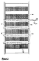
- the bottom of the combustion chamber 1 forms a roller grate consisting of a total of six rollers 5 of approximately 1.5 m in diameter.
- the axes of the rollers 5 lie horizontally and parallel to one another in an inclined plane which is inclined in the direction of the chute 3 about 20 to 30 degrees.
- the shells of the rollers 5 consist - as indicated in the figure - of grate bars 6, each of which extends over an arc of 36 degrees, so that a total of ten grate bars 6 form a closed ring.
- the grate bars 6 are about 5 cm wide.
- Each roller has a drive with which its speed can be continuously adjusted in a range between approximately 0.6 h -1 and 12 h -1 .
- a system consisting essentially of air boxes 7 for supplying primary air to the rollers 5 is arranged under the roller grate. The primary air flows to the rollers 5 can be controlled individually. The primary air distribution is adapted to the different oxygen requirements of the different zones of the grate; the maximum lies in the main combustion zone, ie in the area of the second, third and fourth rollers.
- An uneven fuel layer 8 is indicated on the rollers 5.
- the width of the intermediate piece 9 is in a ratio between about 1: 5 and 1:10 to the roller diameter. It has no air outlets.
- the intermediate piece 9 On the intermediate piece 9 are several holding members at intervals 10 attached, each consisting of a foot 11 and a ring 12.
- the rings 12 enclose with play blow pipes 13. These have a diameter between 20 and 120 mm and are made of heat-resistant steel. They penetrate the two lateral combustion chamber walls 14 and extend approximately to the middle.
- the blowpipes 13 are closed at the free end in the middle of the roll. They are rotatably mounted outside the combustion chamber and can be pivoted about their axis by means of a drive (not shown).
- Each blow pipe 13 is provided with a plurality of blow openings 15 distributed over its length, directed vertically or obliquely upwards. The distance between two adjacent blowing openings is 50 to 1,000 mm.
- the blow openings have diameters between 2 mm and 20 mm.
- each blow pipe 13 has a total of ten blow openings of 0.6 cm diameter arranged at regular intervals over its length of 2.5 m.
- the two blow tubes 13 arranged in a roll winder thus have a total blow section of just under 6 cm 2 .
- the blowing openings can be arranged at different distances along the length of the blowing tube 13 and / or can have different diameters. They can also be arranged differently in the different blowpipes of a roller grate.
- blowpipes may also be missing in the gusset behind the first roller and between the fifth and sixth rollers.
- the blowing openings are designed as Laval nozzles 16a to 16d.
- an inner tube 17 which several rows of openings 18a to 18d on its circumference, 19a to 19d.
- the Openings 18a to 18d free the Laval nozzles 16a to 16d.
- the openings 19a, 19b give the Laval nozzles 16a, 16b free.
- the openings 19c, 19d are, however, among the Laval nozzles 16c, 16d arranged offset, so that the Laval nozzles 16c, 16d are locked in this position.
- axial Displacement of the inner tube 17 in the blow tube 13 can be the Laval nozzles 16a, 16b block and the Laval nozzles 16c, 16d to open.
- the blowpipes 13 are via valves 20, which are through a Time switch device 21 are not to be actuated additional air system shown connected.
- the pressure in Auxiliary air system is 0.05 to 1 MPa above the pressure of the Firebox atmosphere. It stands in with a storage container Compound, the pure oxygen or with oxygen contains enriched air.
- blowpipes 13 preheated and up to 50% enriched with oxygen, blown in. Because the blowguns 13 in the gusset of garbage are enclosed, the blowing jets certainly penetrate the garbage layer.
- the excess pressure in the auxiliary air system can also be significant higher, for example between 0.4 and 1 MPa, preferably so high that the additional air flows Reach supersonic speed, provided, of course, that the blowpipes 13 are equipped with Laval nozzles 16. In this case it is advisable to add air at intervals to blow in intermittently.
- the duration of an air blast is e.g. between 1 s and 100 s, preferably between 10 s and 100 s, the duration of an interval between 1 s and 300 s, preferably between 30 s and 300 s.
- the quantity ratio between additional air and Primary air is consistently between 1:10 to 1: 100, preferably between 1:10 and 1:30. If the ratio e.g. 1:20 and the additional air by adding Oxygen is enriched to 30% Oxygen demand below 0.6% of the primary air volume.
- An additional advantage of the invention is that in the case of roller grates, ash diarrhea in the gusset area is reduced.
Landscapes
- Engineering & Computer Science (AREA)
- Mechanical Engineering (AREA)
- General Engineering & Computer Science (AREA)
- Chemical & Material Sciences (AREA)
- Combustion & Propulsion (AREA)
- Incineration Of Waste (AREA)
- Gasification And Melting Of Waste (AREA)
Description
- Figur 1
- zeigt schematisch eine Seitenansicht eines Walzenrostes.
- Figur 2
- zeigt eine Draufsicht auf den Walzenrost.
- Figur 3
- zeigt in größerem Maßstab eine Einzelheit aus Figur 1.
- Figur 4
- zeigt einen Schnitt durch einen Teil eines Blasrohres.
Claims (15)
- Verfahren zum Verbrennen von Müll auf einem Walzenrost, wobei eine aus Müll gebildete Schicht auf dem Walzenrost in dessen Längsrichtung gefördert und dabei verbrannt wird, wobei der Schicht durch die Rostwalzen des Walzenrostes hindurch von unten Primärluft zugeführt wird und wobei unabhängig von der Primärluft im Bereich schmaler, sich in Querrichtung zwischen den Rostwalzen erstreckender Zonen der Schicht Zusatzluft zugeführt wird, dadurch gekennzeichnet, daß die Zusatzluft mit Sauerstoff angereichert ist und über von dem Müll umschlossene Blasrohre in die Schicht eingeblasen wird.
- Verfahren nach Anspruch 1, dadurch gekennzeichnet, daß Zusatzluft eingeblasen wird, die auf 25 bis 50 % Sauerstoff angereichert ist.
- Verfahren nach Anspruch 1 oder 2, dadurch gekennzeichnet, daß die Zusatzluft stoßweise mit Unterbrechungen zugeführt wird.
- Verfahren nach Anspruch 3, dadurch gekennzeichnet, daß die Zusatzluft mit einem Überdruck von 0,4 bis 1 Mpa relativ zur Feuerraumatmosphäre zugeführt wird.
- Verfahren nach Anspruch 1 oder 2, dadurch gekennzeichnet, daß die Zusatzluft kontinuierlich zugeführt wird.
- Verfahren nach Anspruch 5, dadurch gekennzeichnet, daß die Blasrichtung periodisch geändert wird.
- Verfahren nach Anspruch 5 oder 6, dadurch gekennzeichnet, daß die Zusatzluft mit einem Überdruck von 0,05 bis 0,2 MPa relativ zur Feuerraumatmosphäre zugeführt wird.
- Verfahren nach einem der Ansprüche 1 bis 7, dadurch gekennzeichnet, daß die Menge der Zusatzluft zur Menge der Primärluft in einem Verhältnis 1:10 bis 1:100 steht, vorzugsweise in einem Verhältnis 1:10 bis 1:30.
- Walzenrost zur Verbrennung von Müll, mit mehreren Walzen, deren Achsen waagerecht und parallel zueinander in einer schiefen Ebene angeordnet sind und deren Mantelflächen mit Luftspalten zum Zuführen von Primärluft versehen sind, mit Zwischenstücken, die in den Zwickeln benachbarter Walzen angeordnet sind und den Zwischenraum zwischen den beiden Walzen überbrücken und mit einem System zum Zuführen von Primärluft in das Innere der Walzen und einem separaten System zum Zuführen von Zusatzluft in die Zwickel, dadurch gekennzeichnet, daß zumindest in der Hauptverbrennungszone in den Zwickeln zu den Walzenachsen parallele Blasrohre (13) liegen, welche an das Zusatzluftsystem angeschlossen und mit Blasöffnungen (15) versehen sind, und daß das Zusatzluftsystem mit Sauerstoff angereicherte Luft enthält.
- Walzenrost nach Anspruch 9, dadurch gekennzeichnet, daß die Blasrohre (13) durch Halteorgane (10) an den Zwischenstücken (9) befestigt sind.
- Walzenrost nach Anspruch 9 oder 10, dadurch gekennzeichnet, daß die Blasrohre (13) um ihre Achse drehbar sind.
- Walzenrost nach einem der Ansprüche 9 bis 11, dadurch gekennzeichnet, daß in dem Zwickel zwei Blasrohre (13) angeordnet sind, von denen jedes eine Feuerraumwand (14) durchdringt und bis zur Mitte reicht.
- Walzenrost nach einem der Ansprüche 9 bis 12, dadurch gekennzeichnet, daß die Blasöffnungen (15) als Lavaldüsen (16) ausgebildet sind.
- Walzenrost nach einem der Ansprüche 9 bis 13, dadurch gekennzeichnet, daß die Blasöffnungen (15) einzeln oder gruppenweise verschließbar sind.
- Walzenrost nach einem der Ansprüche 9 bis 14, dadurch gekennzeichnet, daß zwischen Blasrohr (13) und Zusatzluftsystem ein Ventil (20) angeordnet ist, welches durch eine Zeitschaltvorrichtung (21) gesteuert ist.
Priority Applications (12)
| Application Number | Priority Date | Filing Date | Title |
|---|---|---|---|
| DE59508468T DE59508468D1 (de) | 1995-03-21 | 1995-03-21 | Verfahren und Walzenrost zum Verbrennen von Müll |
| PT95104113T PT733854E (pt) | 1995-03-21 | 1995-03-21 | Processo e grelha de rolos para incineracao de residuos |
| AT95104113T ATE193935T1 (de) | 1995-03-21 | 1995-03-21 | Verfahren und walzenrost zum verbrennen von müll |
| ES95104113T ES2148366T3 (es) | 1995-03-21 | 1995-03-21 | Procedimiento y parrilla de rodillos para quemar basuras. |
| DK95104113T DK0733854T3 (da) | 1995-03-21 | 1995-03-21 | Fremgangsmåde og valserist til forbrænding af affald |
| EP95104113A EP0733854B1 (de) | 1995-03-21 | 1995-03-21 | Verfahren und Walzenrost zum Verbrennen von Müll |
| TW085103141A TW303419B (de) | 1995-03-21 | 1996-03-15 | |
| KR1019970706548A KR19980703145A (ko) | 1995-03-21 | 1996-03-18 | 쓰레기 소각용 롤러 격자 및 소각 방법 |
| JP8528068A JPH11502298A (ja) | 1995-03-21 | 1996-03-18 | ゴミ焼却方法及びゴミ焼却用ローラ火格子 |
| CA002223129A CA2223129A1 (en) | 1995-03-21 | 1996-03-18 | Method and roller grill for burning refuse |
| US08/945,397 US5983811A (en) | 1995-03-21 | 1996-03-18 | Method and roller grill for burning refuse |
| PCT/EP1996/001153 WO1996029539A1 (de) | 1995-03-21 | 1996-03-18 | Verfahren und walzenrost zum verbrennen von müll |
Applications Claiming Priority (1)
| Application Number | Priority Date | Filing Date | Title |
|---|---|---|---|
| EP95104113A EP0733854B1 (de) | 1995-03-21 | 1995-03-21 | Verfahren und Walzenrost zum Verbrennen von Müll |
Publications (2)
| Publication Number | Publication Date |
|---|---|
| EP0733854A1 EP0733854A1 (de) | 1996-09-25 |
| EP0733854B1 true EP0733854B1 (de) | 2000-06-14 |
Family
ID=8219090
Family Applications (1)
| Application Number | Title | Priority Date | Filing Date |
|---|---|---|---|
| EP95104113A Expired - Lifetime EP0733854B1 (de) | 1995-03-21 | 1995-03-21 | Verfahren und Walzenrost zum Verbrennen von Müll |
Country Status (12)
| Country | Link |
|---|---|
| US (1) | US5983811A (de) |
| EP (1) | EP0733854B1 (de) |
| JP (1) | JPH11502298A (de) |
| KR (1) | KR19980703145A (de) |
| AT (1) | ATE193935T1 (de) |
| CA (1) | CA2223129A1 (de) |
| DE (1) | DE59508468D1 (de) |
| DK (1) | DK0733854T3 (de) |
| ES (1) | ES2148366T3 (de) |
| PT (1) | PT733854E (de) |
| TW (1) | TW303419B (de) |
| WO (1) | WO1996029539A1 (de) |
Families Citing this family (3)
| Publication number | Priority date | Publication date | Assignee | Title |
|---|---|---|---|---|
| TW457354B (en) | 1999-08-20 | 2001-10-01 | Von Roll Umwelttechnik Ag | Plant and grate block for the thermal treatment of waste materials |
| DE10050575C5 (de) * | 2000-10-12 | 2009-10-29 | Martin GmbH für Umwelt- und Energietechnik | Verfahren zum Verbrennen von Abfallprodukten |
| US6964237B2 (en) * | 2003-06-30 | 2005-11-15 | Mark P. Hepp | Grate block for a refuse incineration grate |
Family Cites Families (10)
| Publication number | Priority date | Publication date | Assignee | Title |
|---|---|---|---|---|
| DE600546C (de) * | 1931-11-21 | 1934-07-25 | Friedrich Schmid | Walzenrost aus hohlen Walzen |
| US2367590A (en) * | 1941-06-23 | 1945-01-16 | George Salem Pettapiece | Burner unit |
| US3812794A (en) * | 1972-09-21 | 1974-05-28 | F Taylor | Stairstep jet pulse incinerator |
| JPS56165818A (en) * | 1980-05-23 | 1981-12-19 | Mitsubishi Heavy Ind Ltd | Method and apparatus for incineration |
| US5044288A (en) * | 1988-12-01 | 1991-09-03 | Barlow James L | Method and apparatus for the efficient combustion of a mass fuel |
| DE3941750A1 (de) * | 1988-12-20 | 1990-06-21 | Pauli Balduin | Zuteiler fuer rostfeuerung |
| SU1756741A1 (ru) * | 1989-11-21 | 1992-08-23 | Научно-Производственное Объединение По Исследованию И Проектированию Энергетического Оборудования Им.И.И.Ползунова | Топка дл сжигани твердых бытовых отходов |
| US5042401A (en) * | 1990-06-04 | 1991-08-27 | Westinghouse Electric Corp. | Water cooled rolling grate incinerator |
| US5405537A (en) * | 1993-03-26 | 1995-04-11 | Air Products And Chemicals, Inc. | Process for combusting dewatered sludge waste in a municipal solid waste incinerator |
| DE4316343A1 (de) * | 1993-05-15 | 1994-11-17 | Babcock Energie Umwelt | Walzenrost für Verbrennungsanlagen |
-
1995
- 1995-03-21 DE DE59508468T patent/DE59508468D1/de not_active Expired - Fee Related
- 1995-03-21 AT AT95104113T patent/ATE193935T1/de not_active IP Right Cessation
- 1995-03-21 DK DK95104113T patent/DK0733854T3/da active
- 1995-03-21 ES ES95104113T patent/ES2148366T3/es not_active Expired - Lifetime
- 1995-03-21 PT PT95104113T patent/PT733854E/pt unknown
- 1995-03-21 EP EP95104113A patent/EP0733854B1/de not_active Expired - Lifetime
-
1996
- 1996-03-15 TW TW085103141A patent/TW303419B/zh active
- 1996-03-18 CA CA002223129A patent/CA2223129A1/en not_active Abandoned
- 1996-03-18 KR KR1019970706548A patent/KR19980703145A/ko not_active Withdrawn
- 1996-03-18 WO PCT/EP1996/001153 patent/WO1996029539A1/de not_active Ceased
- 1996-03-18 JP JP8528068A patent/JPH11502298A/ja not_active Ceased
- 1996-03-18 US US08/945,397 patent/US5983811A/en not_active Expired - Fee Related
Also Published As
| Publication number | Publication date |
|---|---|
| ES2148366T3 (es) | 2000-10-16 |
| US5983811A (en) | 1999-11-16 |
| EP0733854A1 (de) | 1996-09-25 |
| KR19980703145A (ko) | 1998-10-15 |
| TW303419B (de) | 1997-04-21 |
| ATE193935T1 (de) | 2000-06-15 |
| DE59508468D1 (de) | 2000-07-20 |
| CA2223129A1 (en) | 1996-09-26 |
| DK0733854T3 (da) | 2000-11-06 |
| PT733854E (pt) | 2000-12-29 |
| WO1996029539A1 (de) | 1996-09-26 |
| JPH11502298A (ja) | 1999-02-23 |
Similar Documents
| Publication | Publication Date | Title |
|---|---|---|
| DE2815486C2 (de) | Brennerofen | |
| DE2929056C2 (de) | ||
| DE69203023T2 (de) | Brenner für einen Drehrohrofen. | |
| DE2615369C3 (de) | Verfahren zur Rauchgaskonditionierung in Abfallverbrennungsanlagen mit Wärmeverwertung, insbesondere für kommunalen und industriellen Müll, und Vorrichtung zur Durchführung des Verfahrens | |
| DE4217070C2 (de) | Verbrennungsvorrichtung und -verfahren | |
| EP0954722B1 (de) | Mit wasser gekühlter verbrennungsrost | |
| DE2231001A1 (de) | Muellverbrennungsofen | |
| DE2646130A1 (de) | Druckluftfoerdereinrichtung | |
| EP0733855B1 (de) | Walzenrost | |
| EP0733854B1 (de) | Verfahren und Walzenrost zum Verbrennen von Müll | |
| DE3420020A1 (de) | Roststab sowie rostwalze fuer den walzenrost z.b. einer muellverbrennungsanlage oder dergleichen | |
| EP0919771B1 (de) | Verfahren zum Verbrennen von Feststoffen auf einem wassergekühlten Schub-Verbrennungsrost, sowie Rostplatte und Rost zur Ausübung des Verfahrens | |
| EP0798510B1 (de) | Heizkessel | |
| CH615745A5 (de) | ||
| EP1001218B1 (de) | Wassergekühlter Verbrennungsrost, sowie Verfahren zum Verbrennen von Kehricht auf demselben | |
| DE3614177C2 (de) | Brennkammer | |
| DE958419C (de) | Staubfeuerung zum Verbrennen von kleinkoernigem Brennstoff | |
| DE589261C (de) | Vorrichtung zur unvollstaendigen Verbrennung pulverfoermigen Brennstoffes mit schleifenfoermiger Flammenfuehrung in einer Kammer | |
| DE2816282C2 (de) | Müllverbrennungsofen mit einem Wirbelbett | |
| EP0140075B1 (de) | Staubeintrag in eine heisse Zone | |
| DE3213394C2 (de) | Vergaser für die Erzeugung von brennbaren Gasen aus festen organischen Stoffen | |
| AT201754B (de) | Rostfeuerung für die Verbrennung von stark wasserhaltigem, minderwertigem Brennstoff | |
| DE864598C (de) | Anwendung des Verfahrens nach Patent 808107 bei einer kombinierten Brennstaub-Rost-Feuerung und Ausbildung derselben | |
| AT263188B (de) | Müllverbrennungsofen | |
| DE3037075C2 (de) | Brennstoff-Fördereinrichtung für eine Rostfeuerung |
Legal Events
| Date | Code | Title | Description |
|---|---|---|---|
| PUAI | Public reference made under article 153(3) epc to a published international application that has entered the european phase |
Free format text: ORIGINAL CODE: 0009012 |
|
| AK | Designated contracting states |
Kind code of ref document: A1 Designated state(s): AT BE CH DE DK ES FR GB IT LI LU NL PT SE |
|
| 17P | Request for examination filed |
Effective date: 19970304 |
|
| 17Q | First examination report despatched |
Effective date: 19990308 |
|
| GRAG | Despatch of communication of intention to grant |
Free format text: ORIGINAL CODE: EPIDOS AGRA |
|
| GRAG | Despatch of communication of intention to grant |
Free format text: ORIGINAL CODE: EPIDOS AGRA |
|
| GRAH | Despatch of communication of intention to grant a patent |
Free format text: ORIGINAL CODE: EPIDOS IGRA |
|
| 17Q | First examination report despatched |
Effective date: 19990308 |
|
| GRAH | Despatch of communication of intention to grant a patent |
Free format text: ORIGINAL CODE: EPIDOS IGRA |
|
| GRAA | (expected) grant |
Free format text: ORIGINAL CODE: 0009210 |
|
| AK | Designated contracting states |
Kind code of ref document: B1 Designated state(s): AT BE CH DE DK ES FR GB IT LI LU NL PT SE |
|
| REF | Corresponds to: |
Ref document number: 193935 Country of ref document: AT Date of ref document: 20000615 Kind code of ref document: T |
|
| REG | Reference to a national code |
Ref country code: CH Ref legal event code: EP |
|
| RAP2 | Party data changed (patent owner data changed or rights of a patent transferred) |
Owner name: AIR PRODUCTS GMBH Owner name: BBP ENVIRONMENT GMBH |
|
| REF | Corresponds to: |
Ref document number: 59508468 Country of ref document: DE Date of ref document: 20000720 |
|
| RAP2 | Party data changed (patent owner data changed or rights of a patent transferred) |
Owner name: BBP ENVIRONMENT GMBH |
|
| GBT | Gb: translation of ep patent filed (gb section 77(6)(a)/1977) |
Effective date: 20000726 |
|
| ET | Fr: translation filed | ||
| NLT2 | Nl: modifications (of names), taken from the european patent patent bulletin |
Owner name: BBP ENVIRONMENT GMBH EN AIR PRODUCTS GMBH |
|
| ITF | It: translation for a ep patent filed | ||
| NLT2 | Nl: modifications (of names), taken from the european patent patent bulletin |
Owner name: BBP ENVIRONMENT GMBH |
|
| REG | Reference to a national code |
Ref country code: ES Ref legal event code: FG2A Ref document number: 2148366 Country of ref document: ES Kind code of ref document: T3 |
|
| REG | Reference to a national code |
Ref country code: DK Ref legal event code: T3 |
|
| REG | Reference to a national code |
Ref country code: PT Ref legal event code: SC4A Free format text: AVAILABILITY OF NATIONAL TRANSLATION Effective date: 20000914 |
|
| PG25 | Lapsed in a contracting state [announced via postgrant information from national office to epo] |
Ref country code: LU Free format text: LAPSE BECAUSE OF NON-PAYMENT OF DUE FEES Effective date: 20010321 Ref country code: GB Free format text: LAPSE BECAUSE OF NON-PAYMENT OF DUE FEES Effective date: 20010321 Ref country code: DK Free format text: LAPSE BECAUSE OF NON-PAYMENT OF DUE FEES Effective date: 20010321 Ref country code: AT Free format text: LAPSE BECAUSE OF NON-PAYMENT OF DUE FEES Effective date: 20010321 |
|
| PG25 | Lapsed in a contracting state [announced via postgrant information from national office to epo] |
Ref country code: SE Free format text: LAPSE BECAUSE OF NON-PAYMENT OF DUE FEES Effective date: 20010322 Ref country code: ES Free format text: LAPSE BECAUSE OF NON-PAYMENT OF DUE FEES Effective date: 20010322 |
|
| PG25 | Lapsed in a contracting state [announced via postgrant information from national office to epo] |
Ref country code: LI Free format text: LAPSE BECAUSE OF NON-PAYMENT OF DUE FEES Effective date: 20010331 Ref country code: CH Free format text: LAPSE BECAUSE OF NON-PAYMENT OF DUE FEES Effective date: 20010331 Ref country code: BE Free format text: LAPSE BECAUSE OF NON-PAYMENT OF DUE FEES Effective date: 20010331 |
|
| PLBE | No opposition filed within time limit |
Free format text: ORIGINAL CODE: 0009261 |
|
| STAA | Information on the status of an ep patent application or granted ep patent |
Free format text: STATUS: NO OPPOSITION FILED WITHIN TIME LIMIT |
|
| 26N | No opposition filed | ||
| BERE | Be: lapsed |
Owner name: BBP ENVIRONMENT G.M.B.H. Effective date: 20010331 |
|
| PG25 | Lapsed in a contracting state [announced via postgrant information from national office to epo] |
Ref country code: NL Free format text: LAPSE BECAUSE OF NON-PAYMENT OF DUE FEES Effective date: 20011001 |
|
| EUG | Se: european patent has lapsed |
Ref document number: 95104113.6 |
|
| GBPC | Gb: european patent ceased through non-payment of renewal fee |
Effective date: 20010321 |
|
| REG | Reference to a national code |
Ref country code: CH Ref legal event code: PL |
|
| REG | Reference to a national code |
Ref country code: DK Ref legal event code: EBP |
|
| PG25 | Lapsed in a contracting state [announced via postgrant information from national office to epo] |
Ref country code: FR Free format text: LAPSE BECAUSE OF NON-PAYMENT OF DUE FEES Effective date: 20011130 |
|
| NLV4 | Nl: lapsed or anulled due to non-payment of the annual fee |
Effective date: 20011001 |
|
| REG | Reference to a national code |
Ref country code: FR Ref legal event code: ST |
|
| PG25 | Lapsed in a contracting state [announced via postgrant information from national office to epo] |
Ref country code: DE Free format text: LAPSE BECAUSE OF NON-PAYMENT OF DUE FEES Effective date: 20020101 |
|
| PG25 | Lapsed in a contracting state [announced via postgrant information from national office to epo] |
Ref country code: PT Free format text: LAPSE BECAUSE OF NON-PAYMENT OF DUE FEES Effective date: 20020930 |
|
| REG | Reference to a national code |
Ref country code: PT Ref legal event code: MM4A Free format text: LAPSE DUE TO NON-PAYMENT OF FEES Effective date: 20020930 |
|
| REG | Reference to a national code |
Ref country code: ES Ref legal event code: FD2A Effective date: 20030303 |
|
| PG25 | Lapsed in a contracting state [announced via postgrant information from national office to epo] |
Ref country code: IT Free format text: LAPSE BECAUSE OF NON-PAYMENT OF DUE FEES Effective date: 20050321 |
|
| PG25 | Lapsed in a contracting state [announced via postgrant information from national office to epo] |
Ref country code: PT Free format text: LAPSE BECAUSE OF NON-PAYMENT OF DUE FEES Effective date: 20010321 |