EP0733499A1 - Aufhängungslenker - Google Patents
Aufhängungslenker Download PDFInfo
- Publication number
- EP0733499A1 EP0733499A1 EP96104721A EP96104721A EP0733499A1 EP 0733499 A1 EP0733499 A1 EP 0733499A1 EP 96104721 A EP96104721 A EP 96104721A EP 96104721 A EP96104721 A EP 96104721A EP 0733499 A1 EP0733499 A1 EP 0733499A1
- Authority
- EP
- European Patent Office
- Prior art keywords
- arm
- suspension arm
- region
- suspension
- end portion
- Prior art date
- Legal status (The legal status is an assumption and is not a legal conclusion. Google has not performed a legal analysis and makes no representation as to the accuracy of the status listed.)
- Granted
Links
Images


Classifications
-
- B—PERFORMING OPERATIONS; TRANSPORTING
- B60—VEHICLES IN GENERAL
- B60G—VEHICLE SUSPENSION ARRANGEMENTS
- B60G7/00—Pivoted suspension arms; Accessories thereof
-
- B—PERFORMING OPERATIONS; TRANSPORTING
- B60—VEHICLES IN GENERAL
- B60G—VEHICLE SUSPENSION ARRANGEMENTS
- B60G7/00—Pivoted suspension arms; Accessories thereof
- B60G7/001—Suspension arms, e.g. constructional features
-
- B—PERFORMING OPERATIONS; TRANSPORTING
- B60—VEHICLES IN GENERAL
- B60G—VEHICLE SUSPENSION ARRANGEMENTS
- B60G2206/00—Indexing codes related to the manufacturing of suspensions: constructional features, the materials used, procedures or tools
- B60G2206/01—Constructional features of suspension elements, e.g. arms, dampers, springs
- B60G2206/10—Constructional features of arms
- B60G2206/124—Constructional features of arms the arm having triangular or Y-shape, e.g. wishbone
Definitions
- the present invention relates to a suspension arm formed by press working a plate-shaped member.
- suspensions such as a double wishbone type, a strut type, a multi-link type, a trailing arm type, and the like. Accordingly, there are various types of suspension arms forming the suspensions.
- suspension arms such as an A-type arm, an L-type arm, an I-type arm and the like, as well as various structures for suspension arms such as a structure in which a pipe-shaped member or a steel plate is press worked, an aluminum forged structure, and the like.
- suspension arms As described above, there are various types of suspension arms, and among these, a suspension arm which is fabricated by press working a single steel plate will be described hereinafter.
- the structure disclosed in Japanese Utility Model Application Laid-Open No. 61-57009 is an example of such a suspension arm.
- a suspension arm 100 includes a main portion 100A, which has a substantially U-shaped cross-section open toward the bottom of the vehicle, and flange portions 100B, which are provided at the lower end portions of the main portion 100A and which are bent in the longitudinal direction of the vehicle in directions of moving away from one another.
- the suspension arm 100 has a substantially heart-shaped open cross-sectional configuration.
- the suspension arm 100 is fabricated by press working a single steel plate, and, as can be seen when viewed from above, is a substantially V-shaped or A-type arm.
- the suspension disclosed in the aforementioned publication is a strut-type suspension. More specifically, the vehicle inner side distal ends of the bifurcations of the suspension arm 100 are connected to a vehicle body member 104 via bushes 102 so as to be freely swingable. Further, the vehicle outer side end portion of the suspension arm 100 is connected to the lower end portion of an axle carrier 106 which supports a wheel. The lower end portion of a shock absorber 110, around which a coil spring 108 is disposed, is connected to the upper end portion of the axle carrier 106.
- an object of the present invention is to provide a suspension arm which is fabricated by press forming and which can ensure sufficient rigidity without leading to drawbacks such as an increase in weight or the like.
- a first aspect of the present invention is a suspension arm formed by press working a plate-shaped member, wherein in a case in which, while a vehicle is traveling, a load is inputted to the suspension arm in a direction intersecting a direction in which the suspension arm swings, at least a region at which a maximum stress is generated is a non-end portion of the plate-shaped member.
- the suspension arm of the first aspect is more advantageous in terms of rigidity than a case in which the region at which the maximum stress is generated is an end region (a flange portion) such as in conventional structures. More specifically, the stress, which is caused by bending which arises when load in the direction intersecting the swinging direction of the arm is inputted to the suspension arm, can be decreased in accordance with the present invention. As a result, not only is there no need to make the plate-shaped member thicker in order to reinforce the region at which the maximum stress is generated, but also, sufficient rigidity can be ensured even if the plate-shaped member is thin.
- the suspension arm has an arm portion which is disposed so as to be swingable around a line extending along a substantially longitudinal direction of the vehicle and whose longitudinal direction is a direction intersecting the substantially longitudinal direction of the vehicle, and an edge portion of the arm portion in the substantially longitudinal direction of the vehicle is a non-end portion of the plate-shaped member.
- the suspension arm includes an arm portion which is disposed so as to be swingable around a line extending along the substantially longitudinal direction of the vehicle and whose longitudinal direction is a direction intersecting the substantially longitudinal direction of the vehicle.
- This type of suspension arm has the same operation as that of the first aspect because, in accordance with the present invention, an end portion of the arm portion in the substantially longitudinal direction of the vehicle is the non-end portion of the plate-shaped member of the first aspect.
- the suspension arm relating to the second aspect also is advantageous in terms of rigidity. There is no need for reinforcement, and sufficient rigidity can be ensured even if the plate-shaped member is thin.
- the end portion of the plate-shaped member is bent toward another region of the suspension arm.
- the end portion of the plate-shaped member is bent toward another region of the suspension arm in either the first or the second aspect. Therefore, the region of the suspension arm at which the maximum stress is generated is not the end portion of the plate-shaped member. Moreover, by bending the end portion of the plate-shaped member toward another region of the suspension arm, the section modulus of the suspension arm itself can be increased, and the structure is advantageous in terms of rigidity.
- the end portion of the plate-shaped member is adjacent to the other region of the suspension arm.
- the end portion of the plate-shaped member is adjacent to the other region of the suspension arm in the third aspect. Therefore, when a large load is applied at least to the suspension arm, the end portion is made to contact the other region of the suspension arm, and deformation of the suspension arm can be controlled. As a result, this structure is even more advantageous in terms of rigidity.
- the cross-sectional configuration of the arm in the region at which a maximum stress is generated may be a C-shaped configuration, a horseshoe-shaped configuration, a generally rectangular configuration, or the like.
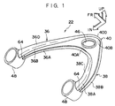
- Fig. 1 is a perspective view as seen from a bottom side of an upper arm relating to a first embodiment.
- Fig. 2 is a plan view of the upper arm illustrated in Fig. 1.
- Fig. 3A is a cross-sectional view taken along line A-A of Fig. 2.
- Fig. 3B is a cross-sectional view taken along line B-B of Fig. 2.
- Fig. 3C is a cross-sectional view taken along line C-C of Fig. 2.
- Fig. 3D is a cross-sectional view taken along line D-D of Fig. 2.
- Fig. 3E is a cross-sectional view taken along line E-E of Fig. 2.
- Fig. 4 is a side view of a distal end portion of the upper arm illustrated in Fig. 1, as viewed in the direction of arrow Q in Fig. 2.
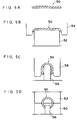
- Figs. 5A through 5D are process views illustrating processes for fabricating the upper arm illustrated in Fig. 1.
- Fig. 6 is an overall perspective view illustrating a front suspension equipped with the upper arm illustrated in Fig. 1.
- Fig. 7 is a perspective view corresponding to Fig. 1 and illustrating an L-type arm relating to another embodiment.
- Fig. 8A is a plan view of a lower arm relating to a second embodiment.
- Fig. 8B is a side view of the lower arm relating to the second embodiment.
- Fig. 8C is a side view of the lower arm relating to the second embodiment.
- Fig. 9 is a cross-sectional view, taken along line 9-9, of the lower arm illustrated in Fig. 8A.
- Fig. 10 is a cross-sectional view, corresponding to Fig. 9, of a lower arm relating to a comparative example.
- Figs. 11A and 11B are explanatory views for explaining effects in a case in which the lower arm illustrated in Fig. 9 is used.
- Fig. 12 is a cross-sectional view, corresponding to Fig. 9, of a lower arm relating to a third embodiment.
- Fig. 13 is an explanatory view for explaining effects in a case in which the lower arm illustrated in Fig. 12 is used.
- Fig. 14 is also an explanatory view for explaining effects in a case in which the lower arm illustrated in Fig. 12 is used.
- Fig. 15 is also an explanatory view for explaining effects in a case in which the lower arm illustrated in Fig. 12 is used.
- Fig. 16 is also an explanatory view for explaining effects in a case in which the lower arm illustrated in Fig. 12 is used.
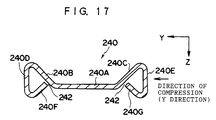
- Fig. 17 is a cross-sectional view, corresponding to Fig. 12, of a lower arm relating to a fourth embodiment.
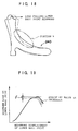
- Fig. 18 is an explanatory view for explaining effects in a case in which the lower arm illustrated in Fig. 17 is used.
- Fig. 19 is a graph for explaining effects in a case in which the lower arm illustrated in Fig. 17 is used.
- Fig. 20 is a cross-sectional view corresponding to Fig. 17 and illustrating an example of providing ribs at the lower arm illustrated in Fig. 17.
- Fig. 21 is a cross-sectional view illustrating another structure which achieves the same effects as those achieved by the lower arm illustrated in Fig. 17.
- Fig. 22 is a perspective view illustrating a structure of a suspension arm relating to a conventional example.
- FIG. 1 A first embodiment of the present invention will be described hereinafter on the basis of Figs. 1 through 6.
- the first embodiment corresponds to the embodiment of the above-described first and second aspects.
- the arrow FR points toward the front of the vehicle
- the arrow UP points toward the top of the vehicle
- the arrow IN points toward the interior of the vehicle.
- Fig. 6 is a perspective view of a double wishbone independent suspension type front suspension 10. First, the overall structure of the front suspension 10 will be summarized by using this figure.
- a subframe 12 is disposed under the front portion of the vehicle.
- the subframe 12 is formed in a substantial "#" or “tic-tac-toe board” shape as viewed from above.
- Front frame rods 14 are mounted between the front end portions of side portions 12A of the subframe 12 so as to intersect each other.
- the front frame rods 14 have a bracing function to increase the rigidity of the subframe 12.
- Unillustrated rear frame rods are suspended between the rear end portions of the side portions 12A of the subframe 12.
- Axle carriers 16 are disposed at the outer sides of the side portions 12A of the subframe 12.
- the axle carrier 16 is formed by a boss portion 16A, a lower end portion 16B which is disposed directly under the boss portions 16A, and an extending portion 16C which extends from the boss portion 16A toward the top of the vehicle.
- a disc rotor 18 for braking which rotates together with the wheel, is supported at the boss portion 16A of the axle carrier 16 so as to be freely rotatable.
- An L-type lower arm 20 is disposed at the lower end portion of the axle carrier 16.
- An A-type upper arm 22 is disposed at the upper end portion of the axle carrier 16 substantially parallel to the lower arm 20.
- the lower arm 20 is formed by a first arm 24 and a second arm 26.
- the first arm 24 is disposed along a substantially transverse direction of the vehicle, and the second arm 26 is mounted by bolts to the first arm 24 so as to be disposed at an angle with respect to the first arm 24.
- the end portion of the lower arm 20 at the vehicle exterior side is joined to the lower end portion of the axle carrier 16 via an unillustrated ball joint.
- the respective distal end portions of the first arm 24 and the second arm 26, which are the end portions of the lower arm 20 at the vehicle interior side, are joined to the side portion 12A of the subframe 12 via lower arm bushes 28.
- a shock absorber 30 is supported at the upper end portion of the first arm 24 of the lower arm 20.
- a stabilizer bar 32 which is substantially U-shaped when viewed from above, is joined via stabilizer links 34 to the respective first arms 24.
- the upper arm 22 is, as will be described later, an integrally formed part which is formed by a first arm portion 36, a second arm portion 38, and a connecting portion 40.
- the first arm portion 36 extends forward at an angle toward the vehicle interior, with respect to a substantially longitudinal direction of the vehicle.
- the second arm portion 38 extends rearward at an angle toward the vehicle interior, with respect to the substantially longitudinal direction of the vehicle.
- the connecting portion 40 connects the first arm portion 36 and the second arm portion 38 at the vehicle outer side, and is connected to the upper end portion of the extending portion 16C of the axle carrier 16 via a ball joint 42.
- the end portion of the first arm portion 36 at the vehicle interior side and the end portion of the second arm portion 38 at the vehicle interior side are each joined to the vehicle body via an upper arm bush 44.
- the upper arm 22 is swingable around an axis P (see Fig. 2) of both of the upper arm bushes 44 (i.e., the upper arm 22 is swingable around a line extending along the substantially longitudinal direction of the vehicle).
- Fig. 1 is a perspective view of the upper arm 22 as seen from the bottom side thereof.
- Fig. 2 is a plan view of the upper arm 22.
- Figs. 3A through 3E are cross-sectional views of respective portions of the upper arm 22.
- the upper arm 22, which is formed from the first arm portion 36, the second arm portion 38, and the connecting portion 40, is manufactured by press forming a single plate.
- the connecting portion 40 of the upper arm 22 has a flat, substantially C-shaped cross-section.
- a cylindrical hole 46 for the mounting of the ball joint 42 is formed at the substantially central portion of the connecting portion 40.
- the inner side end portion 40A and the outer side end portion 40B of the connecting portion 40 are bent in directions of approaching each other. Accordingly, a side portion 40C at the innermost side of the connecting portion 40 and a side portion 40D at the outermost side are non-end portions.
- the outer side end portion 40B at the region of line A-A does not bend inwardly in cross-section (see Fig. 3A). However, as will be explained later, this does not present any problems as this region is not a region at which maximum tensile stress is generated.
- the first arm portion 36 and the second arm portion 38 have substantially C-shaped cross-sections which are almost circles, whereas at the distal end portions including the E-E line regions, the first arm portion 36 and the second arm portion 38 have substantially C-shaped cross-sections which are almost horseshoe-shaped.
- an inner side end portion 36A and an outer side end portion 36B of the first arm portion 36 are bent in directions of approaching each other, as are an inner side end portion 38A and an outer side end portion 38B of the second arm portion 38. Accordingly, an innermost side portion 36C and an outermost side portion 36D of the first arm portion 36 and an innermost side portion 38C and an outermost side portion 38D of the second arm portion 38 are non-end portions.
- cylindrical bush mounting sleeves 48 into which the upper arm bushes 44 are press-fit, are fixed by welding to the respective distal end portions of the first arm portion 36 and the second arm portion 38.
- the upper arm 22 of the present embodiment is a press-formed part having an open cross-sectional configuration in which the bottom side of the arm is open.
- the expanded configuration of the upper arm 22 is blanked out from a plate such as a steel plate or the like, so as to form a base material 50.
- the blanked out base material 50 is placed on the horizontal upper end surface of a lower bending tool 52.
- bent flange portions are formed at the transverse direction end portions of the base material 50.
- These bent flange portions are the previously-described inner side end portion 36A and outer side end portion 36B of the first arm portion 36 (or the inner side end portion 38A and outer side end portion 38B of the second arm portion 38).
- a narrow lower insert die 56 is set at the transverse direction intermediate portion of the base material 50.
- an upper bending tool 58 which is narrower than the aforementioned upper bending tool 54, is pushed against the lower insert die 56.
- the base material 50 is formed with a substantially C-shaped cross section.
- the base material 50 is lowered a predetermined amount with the lower insert die 56 still disposed thereat, and in this state, a lower bending tool 60 and an upper bending tool 62, each having a substantially semicircular column shaped concave portion, are pressure-fit, so that the final substantially C-shaped open cross-section which is almost a circle is formed.
- the above-described working method is also known as curling-working.
- the upper arm 22 swings around the line P which is the axis of the upper arm bushes 44 (i.e., the upper arm 22 swings around a line extending along the longitudinal direction of the vehicle).
- load in the longitudinal direction of the vehicle is input from the wheel to the first arm portion 36 and the second arm portion 38 of the upper arm 22.
- This load in the longitudinal direction of the vehicle works as a force which attempts to bend the first arm portion 36 and the second arm portion 38.
- Experimentation has revealed that a relatively large bending moment is applied in particular to the region of the first arm portion 36 at arrow M and the vicinity thereof (see Fig. 2).
- the maximum tensile stress is generated at the region at arrow M and the vicinity thereof.
- the region at arrow M and the vicinity thereof are the outermost side portion 36D of the upper arm 22 (the first arm portion 36). More specifically, because the outer side end portion 36B is bent toward the inner side of the cross section, the region at arrow M and the vicinity thereof are a non-end portion, and therefore, the rigidity is greater than in the conventional art. Accordingly, even if a longitudinal direction load of the same magnitude is applied to the upper arm 22, the maximum tensile stress generated in the region at arrow M and the vicinity thereof is small. Experimentation has revealed that the maximum tensile stress in the present embodiment becomes half or less than half of the maximum tensile stress of the conventional art.
- the upper arm 22 having an open cross-sectional configuration manufactured from a single plate, but also, sufficient rigidity can be ensured because the inner side end portion 36A and the outer side end portion 36B of the first arm portion 36 are bent in directions of approaching each other, as are the inner side end portion 38A and the outer side end portion 38B of the second arm portion 38 (in particular, because the outer side end portion 36B of the first arm portion 36 is bent toward the inner side of the cross section).
- the upper arm 22 i.e., the plate thickness of the upper arm 22
- the upper arm 22 can be made thin. Accordingly, the upper arm 22 can be made lighter, and therefore, the entire vehicle can also be made lighter. Because the upper arm 22 can be made thin, the yield can be improved, which leads to a decrease in costs. Note that if the upper arm 22 is made as thick as conventional structures, an even more rigid upper arm can be obtained.
- the upper arm 22 is formed to have an open cross-sectional configuration in which the bottom side thereof is open.
- a gap 64 (see Fig. 1) is formed continuously even at the portions of the upper arm 22 which are connected to the bush mounting sleeves 48 (the respective distal end portions of the first arm portion 36 and the second arm portion 38). Therefore, even if rain water or the like enters into the upper arm 22, the water can be reliably drained from the interior of the arm. Therefore, accumulation of rain water or the like at the portions connected to the bush mounting sleeves 48 can be prevented.
- Fig. 7 illustrates an example in which the present invention is applied to an L-type arm 70.
- the L-type arm 70 has a first arm portion 72, which is disposed along the substantially transverse direction of the vehicle, and a second arm portion 74, which is bent in the substantially longitudinal direction of the vehicle.
- the L-type arm 70 has an open cross-sectional configuration whose bottom side is open.
- An inner side end portion 72A and an outer side end portion 72B of the first arm portion 72 are bent in directions of approaching each other, as are an inner side end portion 74A and an outer side end portion 74B of the second arm portion 74. Accordingly, an innermost side portion 72C and an outermost side portion 72D of the first arm portion 72 and an innermost side portion 74C and an outermost side portion 74D of the second arm portion 74 are all non-end portions. Therefore, the same effects as those of the previously described embodiment are achieved. Further, for example, load in the vehicle transverse direction when the vehicle is traveling is input to an unillustrated trailing arm which swings around a line extending along the transverse direction of the vehicle.
- the maximum tensile stress would be generated at a region of the trailing arm which is at the outer surface of the arm and which is in the vicinity of an intermediate portion between the vehicle body connecting point and the axle carrier connecting point.
- the present embodiment is applied, the same effects as described previously can be achieved.
- the first aspect can be applied to various types of suspension arms such as A-type, L-type, and I-type suspension arms which include a trailing arm.
- the second aspect may be applied to various types of suspension arms other than those including a trailing arm.
- the upper arm 22 has an open cross-sectional configuration, and the inner side end portions 36A, 38A, 40A and the outer side end portions 36B, 38B, 40B at all of the regions, i.e., at the first arm portion 36, the second arm portion 38 and the connecting portion 40, are bent toward the inner side of the cross section.
- the present invention is not limited to the same, and it suffices that at least the end portion 36B at the region at which the maximum stress is generated is bent toward the inner side of the cross section (i.e, the region at arrow M and the vicinity thereof at the outermost side portion 36D of the first arm portion 36).
- the suspension arm of the first aspect in a case in which, while the vehicle is traveling, a load is inputted to the suspension arm in a direction intersecting a direction in which the suspension arm swings, at least a region at which a maximum stress is generated is a non-end portion of the plate-shaped member.
- this suspension arm includes the feature that the end portions of the plate-shaped member are bent in directions of approaching each other and a predetermined gap (corresponding to the gap 64) is provided between the opposing end portions, the effect that rain water or the like, which enters in while the vehicle is traveling, can be drained from the gap can be achieved even if suspension arm bushes (corresponding to the upper arm bushes 44), which are the points for connection to the vehicle body, are attached to the distal end portions of the suspension arm.
- suspension arm bushes corresponding to the upper arm bushes 44
- FIG. 8A through 11 A second embodiment of the present invention will be described on the basis of Figs. 8A through 11. Note that the second embodiment corresponds to an embodiment of the previously-described third aspect.
- Figs. 8A through 8C are three views of an L-shaped lower arm 200 relating to the present embodiment.
- the lower arm 200 includes a first arm portion 202, which is disposed along the substantially transverse direction of the vehicle, and a second arm portion 204, which is curved along the substantially longitudinal direction of the vehicle.
- the lower arm 200 has an open cross-sectional configuration in which the bottom side is open.
- the lower arm 200 is fabricated by press working a single plate.
- a bush 206 whose axial direction is the longitudinal direction of the vehicle, is mounted to the inner end portion of the first arm portion 202.
- a bush 208, whose axial direction is the vertical direction of the vehicle, is mounted to the inner end portion of the second arm portion 204.
- a ball joint 210 is mounted to the outer end portion of the second arm portion 204.
- Fig. 9 illustrates the general cross-sectional structure of the second arm portion 204 of the lower arm 200.
- the second arm portion 204 is formed by a main portion 204A, side portions 204B, 204C, and end portions 204D, 204E.
- the main portion 204A is disposed substantially horizontally.
- the side portions 204B, 204C are bent downward from the transverse direction end portions of the main portion 204A and are parallel to one another.
- the end portions 204D, 204E are bent from the lower end portions of the side portions 204B, 204C. Accordingly, at the lower arm 200 as well, the region at which the maximum stress is generated (a vicinity of the position at line 9-9 in Fig. 8) is a non-end portion.
- the feature of the present embodiment is that both of the end portions 204D, 204E are bent toward the inner side of the cross section at acute angles.
- the present embodiment also includes the feature that the end portions 204D, 204E are bent at acute angles toward the inner side of the cross section. Therefore, the section modulus around the Z-axis which runs along the substantially vertical direction of the vehicle can be increased. More specifically, vicinities of the distal ends of the end portions 204D, 204E of the lower arm 200 of the present embodiment illustrated in Fig. 9 are further away from the Z-axis than the distal ends of a lower arm 212 illustrated in Fig. 10, which has the same thickness and cross-sectional area as the lower arm 200 and which has 90 degree end portions in cross section.
- the section modulus around the Z-axis can be increased more in the present embodiment.
- the lower arm 200 has an open cross-sectional configuration, the same rigidity as that of a lower arm having a closed cross-sectional configuration can be ensured. Accordingly, because the portion to which a relatively large bending moment is applied is a non-end portion, the lower arm 200 which is more advantageous in terms of rigidity can be obtained.
- Fig. 11A illustrates an example of a lower arm 214 whose end portions 214D, 214E are bent toward the outer side of the cross-section. In this case, it is easy for ice to accrete on the end portion 214D which is at the front side of the vehicle.
- Fig. 11B with the lower arm 200 of the present embodiment whose end portions 204D, 204E are bent toward the inner side of the cross section, it is difficult for ice to accrete at the end portions 204D, 204E.
- a third embodiment will be described with reference to Figs. 12 through 16.
- the third embodiment corresponds to an embodiment of the previously-described third aspect.
- a lower arm 220 of the present embodiment is formed by a main portion 220A, inclined portions 220B, 220C, side portions 220D, 220E, and end portions 220F, 220G.
- the main portion 220A is disposed substantially horizontally.
- the inclined portions 220B, 220C are bent so as to incline upwardly from the transverse direction end portions of the main portion 220A.
- the side portions 220D, 220E are bent downwardly from the end portions of the inclined portions 220B, 220C so as to extend parallel to one another.
- the end portions 220F, 220G are bent at acute angles toward the inner side of the cross section from the lower end portions of the side portions 220D, 220E.
- the lower arm 220 is formed such that the transverse direction end portions of the main portion 220A are folded into triangles.
- Gaps 222 each of which has a dimension m, are formed between the distal ends of the end portions 220F, 220G of the lower arm 220 and the proximal ends of the inclined portions 220B, 220C. It is desirable that the dimension m is a dimension which can be welded.
- the section modulus around the Z-axis can be increased, and accretion of ice occurring when the vehicle travels on snow-covered roads and damage to the paint layer can be prevented.
- the suspension arm In a case in which vehicle weights of the same type of vehicle are different, generally, the suspension arm is designed to exhibit a strength which can handle the vehicle having the heavier weight. In this case, either there is excess design and an unnecessarily heavy arm for lighter vehicles, or there is a need to provide two types of arms of different thicknesses.
- the same type of suspension arm can be used for vehicles of various weights by appropriately deciding whether welding is to be effected and, if so, which portion(s) should be welded. More specifically, as in the case of the lower arm 220 illustrated in Fig. 13, both of the end portions 220F, 220G may be welded to the proximal ends of the inclined portions 220B, 220C.
- the strength of the suspension arm can be changed.
- the distal end portions of end portions 230B, 230C are bent parallel along a main portion 230A. If either or both of these distal end portions are spot welded, the strength can be changed so as to correspond to the vehicle.
- the strength can be changed in accordance with the vehicle by welding to side portions 232A, 232B either or both of the distal end portions of end portions 232C, 232D which are folded over at the lower arm 232.
- a fourth embodiment will be described on the basis of Figs. 17 through 21.
- the fourth embodiment corresponds to an embodiment of the previously-described fourth aspect.
- a lower arm 240 of the present embodiment is formed by a main portion 240A, inclined portions 240B, 240C, side portions 240D, 240E, and end portions 240F, 240G.
- the main portion 240A is disposed substantially horizontally.
- the inclined portions 240B, 240C are bent so as to be inclined upward from the transverse direction end portions of the main portion 240A.
- the side portions 240D, 240E are bent downward from the end portions of the inclined portions 240B, 240C so as to extend parallel to one another.
- the end portions 240F, 240G are bent at acute angles toward the inner side of the cross section from the lower end portions of the side portions 240D, 240E. In this way, the lower arm 240 is formed such that the transverse direction end portions of the main portion 240A are folded in triangles.
- the present embodiment is similar to the above-described third embodiment with respect to this point.
- the position of the main portion 240A in the heightwise direction is set lower than that of the main portion 220A of the above-described lower arm 220. Accordingly, the lengths of the inclined portions 240B, 240C in the directions in which they extend are longer than the lengths of the inclined portions 220B, 220C of the lower arm 220.
- the distal end portions of the end portions 240F, 240G oppose these portions which have become longer.
- the end portions 240F, 240G are disposed adjacent to the inclined portions 240B, 240C so as to be orthogonal thereto. Gaps 242 are formed between the distal end portions of the end portions 240F, 240G and the inclined portions 240B, 240C.
- the lower arm 240 deforms from the state illustrated by the solid line to the state illustrated by the two-dotted chain line with respect to loads pulling the lower ball joint toward the rear of the vehicle.
- a portion b of the lower arm 240 is compressively deformed.
- the distal end portion of the end portion 240G abuts the inclined portion 240C as the side portion 240E of the lower arm 240 deforms.
- the deforming load is transmitted to the main portion 240A which works as a bracing member in the direction of arrow Y illustrated in Fig. 17, so that the deformation of the end portion 240G is controlled.
- Fig. 19 is a graph with the rearward displacement of the lower ball joint on the horizontal axis, and the rearward load on the lower ball joint on the vertical axis.
- the characteristic is as illustrated by the broken line.
- the characteristic is as illustrated by the solid line.
- the amount of energy absorbed during impact increases by the range illustrated by the hatching. Accordingly, in accordance with the present embodiment, not only does the section modulus around the Z-axis increase, but also, the deformation of the lower arm 240 is controlled by the end portion 240G abutting the inclined portion 240C as the lower arm 240 is deforming, so that the deformation proof stress improves, and the amount of energy absorbed during impact can be increased.
- a lower arm 244 illustrated in Fig. 20 is similar to the above-described lower arm 240 with regard to the point that the lower arm 244 includes a main portion 244A, inclined portions 244B, 244C, side portions 244D, 244E, and end portions 244F, 244G, the following points are different.
- the main portion 244 is disposed at the top portion of the cross section, and ribs 246, 248 which are depressed downwardly are formed in vicinities of the end portions of the main portion 244A.
- a main portion 250A is disposed at the bottom portion of the cross section. Distal end portions of end portions 250D, 250E are disposed adjacent to side portions 250B, 250C which rise from the transverse direction end portions of the main portion 250A.
- the deformation is controlled so that deformation proof stress is improved, and the amount of energy absorbed during impact is increased.
Applications Claiming Priority (6)
| Application Number | Priority Date | Filing Date | Title |
|---|---|---|---|
| JP6408895 | 1995-03-23 | ||
| JP6408895 | 1995-03-23 | ||
| JP64088/95 | 1995-03-23 | ||
| JP7220803A JPH08318722A (ja) | 1995-03-23 | 1995-08-29 | サスペンションアーム |
| JP22080395 | 1995-08-29 | ||
| JP220803/95 | 1995-08-29 |
Publications (2)
| Publication Number | Publication Date |
|---|---|
| EP0733499A1 true EP0733499A1 (de) | 1996-09-25 |
| EP0733499B1 EP0733499B1 (de) | 2001-10-17 |
Family
ID=26405219
Family Applications (1)
| Application Number | Title | Priority Date | Filing Date |
|---|---|---|---|
| EP96104721A Expired - Lifetime EP0733499B1 (de) | 1995-03-23 | 1996-03-25 | Aufhängungslenker |
Country Status (6)
| Country | Link |
|---|---|
| US (1) | US5662348A (de) |
| EP (1) | EP0733499B1 (de) |
| JP (1) | JPH08318722A (de) |
| KR (1) | KR100219925B1 (de) |
| CN (1) | CN1137983A (de) |
| DE (1) | DE69615889T2 (de) |
Cited By (7)
| Publication number | Priority date | Publication date | Assignee | Title |
|---|---|---|---|---|
| EP1223058A3 (de) * | 2001-01-12 | 2003-09-10 | Honda Giken Kogyo Kabushiki Kaisha | Aufhängungslenker |
| WO2004065146A1 (en) * | 2003-01-20 | 2004-08-05 | Multimatic Inc. | Structural i-beam automotive suspension arm |
| EP1346855A3 (de) * | 2002-03-22 | 2005-03-23 | Benteler Automobiltechnik GmbH | Querlenker einer Radaufhängung |
| EP1619055A1 (de) * | 2004-07-21 | 2006-01-25 | Ford Global Technologies, LLC, A subsidary of Ford Motor Company | Einschaliger vorderer Querlenker |
| EP1832447A1 (de) | 2006-03-08 | 2007-09-12 | Benteler Automobiltechnik GmbH | Querlenker |
| KR20160138011A (ko) * | 2014-03-27 | 2016-12-02 | 가부시키가이샤 요로즈 | 차량용 암 부품의 제조 방법 및 차량용 암 부품 |
| EP3290242A4 (de) * | 2015-04-29 | 2018-12-19 | Iljin Co., Ltd. | Hybridarm und verfahren zur herstellung davon |
Families Citing this family (47)
| Publication number | Priority date | Publication date | Assignee | Title |
|---|---|---|---|---|
| JP3027922B2 (ja) * | 1995-04-28 | 2000-04-04 | トヨタ自動車株式会社 | アーム及びアームの鍛造方法 |
| US6109632A (en) * | 1998-08-06 | 2000-08-29 | Wei; Jimmy | Front wheel double suspension triangle frame for four-wheel drive automobile |
| JP2000142051A (ja) * | 1998-11-05 | 2000-05-23 | Tokai Rubber Ind Ltd | サスペンションアーム |
| AU2003271365B2 (en) * | 1999-09-02 | 2005-02-17 | Hendrickson International Corporation | Control rod |
| US6308591B1 (en) * | 1999-09-02 | 2001-10-30 | The Boler Company | Control rod |
| US6241267B1 (en) | 1999-12-07 | 2001-06-05 | R. J. Tower Corporation | Control arm for use in vehicle suspension system |
| US6308970B1 (en) * | 1999-12-21 | 2001-10-30 | Daimlerchrysler Corporation | Apparatus for coupling a ball joint to a motor vehicle suspension |
| DE10110492A1 (de) * | 2001-03-05 | 2002-09-19 | Volkswagen Ag | Lenker für eine Radaufhängung |
| KR20020088174A (ko) * | 2001-05-18 | 2002-11-27 | 현대자동차주식회사 | 차량용 트레일링 아암 및 그 제조방법 |
| KR100482055B1 (ko) * | 2001-12-14 | 2005-04-13 | 현대자동차주식회사 | 자동차 현가장치의 로워암 |
| KR100452203B1 (ko) * | 2002-05-30 | 2004-10-08 | 현대자동차주식회사 | 두께 차이를 갖는 현가장치용 로워암 |
| DE10249768B3 (de) * | 2002-10-24 | 2004-07-29 | ZF Lemförder Metallwaren AG | Verfahren zur Herstellung eines Spurstangengehäuses |
| JP4151553B2 (ja) * | 2003-10-09 | 2008-09-17 | トヨタ自動車株式会社 | サスペンション |
| DE102004009722A1 (de) * | 2004-02-25 | 2005-09-22 | Zf Friedrichshafen Ag | Radführungslenker |
| DE102004039175A1 (de) * | 2004-08-12 | 2006-02-23 | Thyssenkrupp Automotive Ag | Querlenker für eine Radaufhängung |
| DE102005004917B4 (de) * | 2005-02-02 | 2013-02-28 | Benteler Automobiltechnik Gmbh | Lenkerbauteil für Radaufhängungen von Kraftfahrzeugen und Verfahren zu seiner Herstellung |
| DE102005035913A1 (de) * | 2005-07-28 | 2007-02-08 | Zf Friedrichshafen Ag | Kraftfahrzeugfahrwerk |
| KR100706461B1 (ko) | 2005-09-22 | 2007-04-10 | 주식회사 동희산업 | 차량의 서스펜션암 구조 |
| US7798503B2 (en) * | 2006-01-16 | 2010-09-21 | The Pullman Company | Cast apex adjustable V-type torque rod |
| DE102007018569B4 (de) * | 2007-04-18 | 2014-07-17 | Gmf Umformtechnik Gmbh | Fahrwerkslenker für ein Kraftfahrzeug |
| KR20090009547A (ko) * | 2007-07-20 | 2009-01-23 | 현대자동차주식회사 | 차량 현가장치의 토션 빔 |
| KR100921054B1 (ko) * | 2007-10-17 | 2009-10-08 | 현대자동차주식회사 | 이중 판상 부재를 이용한 어퍼 암 |
| CA2611281A1 (en) * | 2007-11-20 | 2009-05-20 | Multimatic Inc. | Structural i-beam automotive suspension arm |
| WO2010055747A1 (ja) * | 2008-11-12 | 2010-05-20 | 住友金属工業株式会社 | アーム素材およびその製造方法 |
| IT1398384B1 (it) * | 2009-02-05 | 2013-02-22 | Sistemi Sospensioni Spa | Braccio oscillante per sospensione di veicolo e procedimento per la sua realizzazione |
| DE102010007946A1 (de) * | 2010-02-12 | 2011-08-18 | Benteler Automobiltechnik GmbH, 33102 | Querlenker mit Lagerzapfen und Verfahren zur Herstellung eines Querlenkers |
| DE102011084164A1 (de) * | 2011-10-07 | 2013-04-11 | Zf Friedrichshafen Ag | Verbindungsbauteil für ein Fahrzeug |
| CN102367044B (zh) * | 2011-10-18 | 2013-10-16 | 奇瑞汽车股份有限公司 | 一种汽车双叉臂悬架上摆臂总成 |
| CN104066602B (zh) * | 2011-12-21 | 2016-08-24 | 本田技研工业株式会社 | 悬架臂安装构造 |
| DE102012100719A1 (de) | 2012-01-30 | 2013-08-01 | Gmf Umformtechnik Gmbh | Einschaliger Federlenker |
| JP5765257B2 (ja) * | 2012-02-01 | 2015-08-19 | トヨタ自動車株式会社 | サスペンションアーム |
| JP5376184B2 (ja) * | 2012-10-09 | 2013-12-25 | トヨタ自動車株式会社 | 車両用i型サスペンションアーム |
| US9610818B2 (en) * | 2012-12-10 | 2017-04-04 | Illinois Tool Works Inc. | Ring link assembly |
| EP2759423B1 (de) * | 2013-01-28 | 2015-04-22 | Gestamp Umformtechnik GmbH | Querlenker aus faserverstärktem Kunststoff für eine Radaufhängung eines Fahrzeuges |
| CN103640447B (zh) * | 2013-12-26 | 2016-06-08 | 安徽江淮汽车股份有限公司 | 一种悬架上摆臂结构 |
| JP6294200B2 (ja) * | 2014-09-26 | 2018-03-14 | 本田技研工業株式会社 | 駆動輪の独立懸架装置 |
| DE102014223478A1 (de) * | 2014-11-18 | 2016-05-19 | Zf Friedrichshafen Ag | Strukturbauteil für ein Kraftfahrzeug |
| GB2528735B (en) * | 2015-01-22 | 2017-01-11 | Ford Global Tech Llc | A control arm of a suspension |
| KR101732066B1 (ko) * | 2015-04-29 | 2017-05-08 | 주식회사 일진 | 치핑에 의한 도장면 손상 방지 구조를 가지는 하이브리드 암 |
| JP2016222000A (ja) * | 2015-05-27 | 2016-12-28 | トヨタ自動車株式会社 | サスペンションアーム |
| WO2017115932A1 (ko) * | 2015-12-30 | 2017-07-06 | 주식회사 일진 | 차량용 하이브리드 현가암 및 그 제조방법 |
| WO2017116183A2 (ko) * | 2015-12-30 | 2017-07-06 | 주식회사 일진 | 하이브리드 현가암 |
| JP6335986B2 (ja) * | 2016-08-25 | 2018-05-30 | 日本発條株式会社 | スタビリンク |
| JP7020492B2 (ja) | 2017-11-27 | 2022-02-16 | 日本製鉄株式会社 | 構造部材 |
| CN109318671B (zh) * | 2018-10-24 | 2019-07-16 | 索密克汽车配件有限公司 | 一种汽车摆臂以及其加工工艺和设计方法 |
| KR102607438B1 (ko) * | 2019-01-25 | 2023-11-29 | 주식회사 일진 | 차량용 현가암 |
| CN114025894B (zh) * | 2019-07-04 | 2023-10-24 | 日本制铁株式会社 | 构造部件的制造方法以及制造装置 |
Citations (4)
| Publication number | Priority date | Publication date | Assignee | Title |
|---|---|---|---|---|
| GB2001918A (en) * | 1977-08-02 | 1979-02-14 | King G | Suspension members |
| GB2063783A (en) * | 1979-11-28 | 1981-06-10 | Bendix Corp | Process for constructing a suspension member |
| EP0546610A1 (de) * | 1991-12-10 | 1993-06-16 | Masco Industries, Inc. | Oberführungslenker für ein Fahrzeugaufhängungssystem |
| EP0546612A1 (de) * | 1991-12-10 | 1993-06-16 | Masco Industries, Inc. | Hohlführungslenker für ein Fahrzeugaufhängungssystem |
Family Cites Families (8)
| Publication number | Priority date | Publication date | Assignee | Title |
|---|---|---|---|---|
| JPS58152701A (ja) * | 1982-03-08 | 1983-09-10 | Nippon Filing Co Ltd | 給電装置付き保管設備 |
| JPH0248208Y2 (de) * | 1986-08-22 | 1990-12-18 | ||
| US4761019A (en) * | 1987-09-04 | 1988-08-02 | Chrysler Motors Corporation | Steering knuckle assembly |
| US5236209A (en) * | 1991-12-10 | 1993-08-17 | Masco Industries, Inc. | Process of manufacturing hollow triangular upper control arm for vehicle |
| DE4330103C2 (de) * | 1992-09-22 | 1998-09-10 | Suzuki Motor Co | Aufhängungsarm für die Radaufhängung eines Kraftfahrzeugs |
| JP3151586B2 (ja) * | 1994-03-08 | 2001-04-03 | 本田技研工業株式会社 | 車両用懸架装置のアッパーアーム |
| US5516130A (en) * | 1994-12-22 | 1996-05-14 | Interstate Forging Industries Inc. | Forged control arm |
| JPH08188022A (ja) * | 1995-01-11 | 1996-07-23 | F Tech:Kk | 車両用サスペンションアーム |
-
1995
- 1995-08-29 JP JP7220803A patent/JPH08318722A/ja active Pending
-
1996
- 1996-02-23 KR KR1019960004243A patent/KR100219925B1/ko not_active IP Right Cessation
- 1996-03-20 US US08/619,888 patent/US5662348A/en not_active Expired - Lifetime
- 1996-03-22 CN CN96103728A patent/CN1137983A/zh active Pending
- 1996-03-25 EP EP96104721A patent/EP0733499B1/de not_active Expired - Lifetime
- 1996-03-25 DE DE69615889T patent/DE69615889T2/de not_active Expired - Lifetime
Patent Citations (4)
| Publication number | Priority date | Publication date | Assignee | Title |
|---|---|---|---|---|
| GB2001918A (en) * | 1977-08-02 | 1979-02-14 | King G | Suspension members |
| GB2063783A (en) * | 1979-11-28 | 1981-06-10 | Bendix Corp | Process for constructing a suspension member |
| EP0546610A1 (de) * | 1991-12-10 | 1993-06-16 | Masco Industries, Inc. | Oberführungslenker für ein Fahrzeugaufhängungssystem |
| EP0546612A1 (de) * | 1991-12-10 | 1993-06-16 | Masco Industries, Inc. | Hohlführungslenker für ein Fahrzeugaufhängungssystem |
Cited By (13)
| Publication number | Priority date | Publication date | Assignee | Title |
|---|---|---|---|---|
| EP1223058A3 (de) * | 2001-01-12 | 2003-09-10 | Honda Giken Kogyo Kabushiki Kaisha | Aufhängungslenker |
| EP1346855A3 (de) * | 2002-03-22 | 2005-03-23 | Benteler Automobiltechnik GmbH | Querlenker einer Radaufhängung |
| AU2004205432B2 (en) * | 2003-01-20 | 2008-07-03 | Multimatic Inc. | Structural I-beam automotive suspension arm |
| WO2004065146A1 (en) * | 2003-01-20 | 2004-08-05 | Multimatic Inc. | Structural i-beam automotive suspension arm |
| US7575244B2 (en) | 2003-01-20 | 2009-08-18 | Multimatic, Inc. | Structural I-beam automotive suspension arm |
| EP1619055A1 (de) * | 2004-07-21 | 2006-01-25 | Ford Global Technologies, LLC, A subsidary of Ford Motor Company | Einschaliger vorderer Querlenker |
| EP1832447A1 (de) | 2006-03-08 | 2007-09-12 | Benteler Automobiltechnik GmbH | Querlenker |
| KR20160138011A (ko) * | 2014-03-27 | 2016-12-02 | 가부시키가이샤 요로즈 | 차량용 암 부품의 제조 방법 및 차량용 암 부품 |
| EP3124295A4 (de) * | 2014-03-27 | 2017-04-19 | Yorozu Corporation | Herstellungsverfahren für fahrzeugarmteil und fahrzeugarmteil |
| RU2668939C2 (ru) * | 2014-03-27 | 2018-10-04 | Йорозу Корпорейшн | Способ изготовления детали автомобиля в виде рычага и деталь автомобиля в виде рычага |
| US10596870B2 (en) | 2014-03-27 | 2020-03-24 | Yorozu Corporation | Vehicular arm component manufacturing method and vehicular arm component |
| EP3290242A4 (de) * | 2015-04-29 | 2018-12-19 | Iljin Co., Ltd. | Hybridarm und verfahren zur herstellung davon |
| US10442262B2 (en) | 2015-04-29 | 2019-10-15 | Iljin Co., Ltd. | Hybrid arm and method of manufacturing same |
Also Published As
| Publication number | Publication date |
|---|---|
| DE69615889D1 (de) | 2001-11-22 |
| KR960033810A (ko) | 1996-10-22 |
| US5662348A (en) | 1997-09-02 |
| EP0733499B1 (de) | 2001-10-17 |
| JPH08318722A (ja) | 1996-12-03 |
| DE69615889T2 (de) | 2002-06-20 |
| CN1137983A (zh) | 1996-12-18 |
| KR100219925B1 (ko) | 1999-09-01 |
Similar Documents
| Publication | Publication Date | Title |
|---|---|---|
| US5662348A (en) | Suspension arm | |
| US7431315B2 (en) | Vehicle suspension system with wheel support knuckle and trailing arm attached to toe link | |
| US6122948A (en) | Method of hydroforming a front axle beam | |
| EP0794075B1 (de) | Verformbarer Aufhängungslenker für Kraftfahrzeuge | |
| US7669866B2 (en) | Suspension trailing arm | |
| EP2183122B1 (de) | Verbundlenker mit sperrmechanismus | |
| EP2310217B1 (de) | Querträger für eine verbundlenker-hinterachse für ein kraftfahrzeug und herstellungsverfahren dafür | |
| US8356826B2 (en) | Suspension system for a vehicle | |
| EP2493711B1 (de) | Verbundlenker einer drehachse | |
| US6152468A (en) | Composite suspension control arm shaft for motor vehicles | |
| US6135498A (en) | MacPherson strut tower for passenger car and method of making same | |
| US20090033142A1 (en) | Powered motor vehicle rear axle of a twist-beam axle type | |
| US6428046B1 (en) | Front cradle for a vehicle | |
| KR20100124318A (ko) | 규격화 차량 차축 | |
| EP2132052A1 (de) | Spannungsvermindernde innenmuffe für verbundlenkerachse und zugehöriges verfahren | |
| EP0823363B1 (de) | Karosserie-Tragstruktur für ein Fahrzeug | |
| KR101027409B1 (ko) | 차량용 현가 시스템 | |
| US10086874B2 (en) | Modular vehicle platform and related methods | |
| US9132471B2 (en) | Stress reducing inner sleeve for twist beam and associated method | |
| US20220332161A1 (en) | Semi-Rigid Axle for a Vehicle | |
| EP0546611A1 (de) | Verstärkter oberer Lenker für ein Fahrzeugaufhängungssystem | |
| JPH11115430A (ja) | サスペンションアーム | |
| EP3954557A1 (de) | Traglenker | |
| EP1086836A1 (de) | Haltebock zur Befestigung einer Achsanordnung am Fahrzeugrahmen | |
| JPH11115429A (ja) | サスペンションアーム構造 |
Legal Events
| Date | Code | Title | Description |
|---|---|---|---|
| PUAI | Public reference made under article 153(3) epc to a published international application that has entered the european phase |
Free format text: ORIGINAL CODE: 0009012 |
|
| 17P | Request for examination filed |
Effective date: 19960424 |
|
| AK | Designated contracting states |
Kind code of ref document: A1 Designated state(s): DE FR GB |
|
| 17Q | First examination report despatched |
Effective date: 19980709 |
|
| GRAG | Despatch of communication of intention to grant |
Free format text: ORIGINAL CODE: EPIDOS AGRA |
|
| GRAG | Despatch of communication of intention to grant |
Free format text: ORIGINAL CODE: EPIDOS AGRA |
|
| GRAH | Despatch of communication of intention to grant a patent |
Free format text: ORIGINAL CODE: EPIDOS IGRA |
|
| GRAH | Despatch of communication of intention to grant a patent |
Free format text: ORIGINAL CODE: EPIDOS IGRA |
|
| GRAA | (expected) grant |
Free format text: ORIGINAL CODE: 0009210 |
|
| AK | Designated contracting states |
Kind code of ref document: B1 Designated state(s): DE FR GB |
|
| REF | Corresponds to: |
Ref document number: 69615889 Country of ref document: DE Date of ref document: 20011122 |
|
| ET | Fr: translation filed | ||
| REG | Reference to a national code |
Ref country code: GB Ref legal event code: IF02 |
|
| PLBE | No opposition filed within time limit |
Free format text: ORIGINAL CODE: 0009261 |
|
| STAA | Information on the status of an ep patent application or granted ep patent |
Free format text: STATUS: NO OPPOSITION FILED WITHIN TIME LIMIT |
|
| 26N | No opposition filed | ||
| REG | Reference to a national code |
Ref country code: GB Ref legal event code: 746 Effective date: 20100429 |
|
| PGFP | Annual fee paid to national office [announced via postgrant information from national office to epo] |
Ref country code: FR Payment date: 20120319 Year of fee payment: 17 |
|
| PGFP | Annual fee paid to national office [announced via postgrant information from national office to epo] |
Ref country code: GB Payment date: 20120321 Year of fee payment: 17 |
|
| PGFP | Annual fee paid to national office [announced via postgrant information from national office to epo] |
Ref country code: DE Payment date: 20120411 Year of fee payment: 17 |
|
| GBPC | Gb: european patent ceased through non-payment of renewal fee |
Effective date: 20130325 |
|
| REG | Reference to a national code |
Ref country code: FR Ref legal event code: ST Effective date: 20131129 |
|
| REG | Reference to a national code |
Ref country code: DE Ref legal event code: R119 Ref document number: 69615889 Country of ref document: DE Effective date: 20131001 |
|
| PG25 | Lapsed in a contracting state [announced via postgrant information from national office to epo] |
Ref country code: GB Free format text: LAPSE BECAUSE OF NON-PAYMENT OF DUE FEES Effective date: 20130325 Ref country code: DE Free format text: LAPSE BECAUSE OF NON-PAYMENT OF DUE FEES Effective date: 20131001 Ref country code: FR Free format text: LAPSE BECAUSE OF NON-PAYMENT OF DUE FEES Effective date: 20130402 |