EP0546612A1 - Hohlführungslenker für ein Fahrzeugaufhängungssystem - Google Patents
Hohlführungslenker für ein Fahrzeugaufhängungssystem Download PDFInfo
- Publication number
- EP0546612A1 EP0546612A1 EP92203702A EP92203702A EP0546612A1 EP 0546612 A1 EP0546612 A1 EP 0546612A1 EP 92203702 A EP92203702 A EP 92203702A EP 92203702 A EP92203702 A EP 92203702A EP 0546612 A1 EP0546612 A1 EP 0546612A1
- Authority
- EP
- European Patent Office
- Prior art keywords
- control arm
- modulus
- seam
- stamping
- along
- Prior art date
- Legal status (The legal status is an assumption and is not a legal conclusion. Google has not performed a legal analysis and makes no representation as to the accuracy of the status listed.)
- Withdrawn
Links
- 239000000725 suspension Substances 0.000 title claims abstract description 17
- 238000003466 welding Methods 0.000 claims description 9
- 238000000034 method Methods 0.000 claims description 3
- 230000008569 process Effects 0.000 claims description 3
- 238000005452 bending Methods 0.000 claims 2
- 238000010276 construction Methods 0.000 abstract description 10
- 239000013585 weight reducing agent Substances 0.000 abstract description 5
- 230000006835 compression Effects 0.000 abstract description 4
- 238000007906 compression Methods 0.000 abstract description 4
- 238000004519 manufacturing process Methods 0.000 abstract description 2
- 239000000463 material Substances 0.000 abstract 1
- 230000002787 reinforcement Effects 0.000 description 3
- 239000007787 solid Substances 0.000 description 3
- 229910052751 metal Inorganic materials 0.000 description 2
- 239000002184 metal Substances 0.000 description 2
- 229910001018 Cast iron Inorganic materials 0.000 description 1
- 229910000831 Steel Inorganic materials 0.000 description 1
- 229910052782 aluminium Inorganic materials 0.000 description 1
- XAGFODPZIPBFFR-UHFFFAOYSA-N aluminium Chemical compound [Al] XAGFODPZIPBFFR-UHFFFAOYSA-N 0.000 description 1
- 238000005242 forging Methods 0.000 description 1
- 230000013011 mating Effects 0.000 description 1
- 238000012986 modification Methods 0.000 description 1
- 230000004048 modification Effects 0.000 description 1
- 230000004044 response Effects 0.000 description 1
- 239000010959 steel Substances 0.000 description 1
Images
Classifications
-
- B—PERFORMING OPERATIONS; TRANSPORTING
- B60—VEHICLES IN GENERAL
- B60G—VEHICLE SUSPENSION ARRANGEMENTS
- B60G7/00—Pivoted suspension arms; Accessories thereof
- B60G7/001—Suspension arms, e.g. constructional features
-
- B—PERFORMING OPERATIONS; TRANSPORTING
- B60—VEHICLES IN GENERAL
- B60G—VEHICLE SUSPENSION ARRANGEMENTS
- B60G2206/00—Indexing codes related to the manufacturing of suspensions: constructional features, the materials used, procedures or tools
- B60G2206/01—Constructional features of suspension elements, e.g. arms, dampers, springs
- B60G2206/012—Hollow or tubular elements
-
- B—PERFORMING OPERATIONS; TRANSPORTING
- B60—VEHICLES IN GENERAL
- B60G—VEHICLE SUSPENSION ARRANGEMENTS
- B60G2206/00—Indexing codes related to the manufacturing of suspensions: constructional features, the materials used, procedures or tools
- B60G2206/01—Constructional features of suspension elements, e.g. arms, dampers, springs
- B60G2206/10—Constructional features of arms
- B60G2206/124—Constructional features of arms the arm having triangular or Y-shape, e.g. wishbone
-
- B—PERFORMING OPERATIONS; TRANSPORTING
- B60—VEHICLES IN GENERAL
- B60G—VEHICLE SUSPENSION ARRANGEMENTS
- B60G2206/00—Indexing codes related to the manufacturing of suspensions: constructional features, the materials used, procedures or tools
- B60G2206/01—Constructional features of suspension elements, e.g. arms, dampers, springs
- B60G2206/80—Manufacturing procedures
- B60G2206/81—Shaping
- B60G2206/8103—Shaping by folding or bending
-
- B—PERFORMING OPERATIONS; TRANSPORTING
- B60—VEHICLES IN GENERAL
- B60G—VEHICLE SUSPENSION ARRANGEMENTS
- B60G2206/00—Indexing codes related to the manufacturing of suspensions: constructional features, the materials used, procedures or tools
- B60G2206/01—Constructional features of suspension elements, e.g. arms, dampers, springs
- B60G2206/80—Manufacturing procedures
- B60G2206/82—Joining
- B60G2206/8201—Joining by welding
Definitions
- This invention relates to an upper control arm for a vehicle suspension system and, in particular, to a control arm having a modulus section of hollow construction with an enlarged rim flange for reinforcement of high load stress areas of the control arm.
- Upper control arms are routinely incorporated into the suspension systems of truck and passenger vehicles.
- the typical control arm is generally U-shaped with a ball joint assembly at the apex of the control arm and pivot bar bushings at the ends of the arm for mounting the control arm to a pivot bar assembly.
- the modulus sections between the bushings and the ball joint have been solid sections of cast iron or cast aluminum. It was believed that the traditional cast metal sections were necessary to maintain the integrity of the control arm under the stresses of the suspension system. More recently, the modulus section has been constructed of a steel forging of wire frame design. Although these control arm constructions were strong enough to withstand the stress loads they also were very heavy. In today's vehicle market every aspect of a vehicle is examined for weight reduction.
- Recent proposals for reducing the weight of the suspension system include a hollow, two-piece control arm.
- the square hollow bar section comprises a pair of U-shaped components nested together and double seam welded.
- the control arm has double side walls with single upper and lower walls.
- the double side walls are not located at the compressive stress areas of the arm where additional strength is required.
- the double seam construction requires precise welding over a curving contour which has not been easy to accommodate. Nevertheless, substantial weight reduction over the solid cross-section of the prior known control arms has been accomplished.
- the present invention overcomes the disadvantages of the prior known control arms for vehicle suspension systems by incorporating a modulus section of hollow construction having a substantially triangular configuration in order to distribute the compressive stress loads associated with the suspension system.
- An enlarged rim flange at the joint apex of the stamped triangular construction provides improved reinforcement at the high compression stress areas of modulus section.
- the present invention has a substantially U-shaped configuration with a ball joint assembly at the apex and pivot bar bushings at the ends of the control arm.
- the control arm of the present invention includes a modulus section having a substantially triangular hollow cross-section which reduces the overall weight of the control arm while maintaining strength in key stress areas of the elbow sections.
- the hollow triangular sections are formed through a stamping process wherein the upper apex of the modulus section incorporates a seam weld to form the triangular cross-section.
- an enlarged rim flange is formed along the welded apex seam. This rim flange along the high compression stress ares of the control arm elbow eliminates stress failures along this area and permits double plate FEA modeling resulting in additional load balancing capabilities.
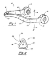
- the control arm 10 is preferably an upper control arm forming a part of a suspension system of a vehicle.
- the control arm 10 has a substantially U-shaped configuration with bushing apertures 12 formed at the ends of the arms 14 and a ball joint receptacle 16 formed at the apex 18 of the control arm 10.
- the ball joint receptacle 16 is adapted to cooperate with a ball joint assembly (not shown) and may include a ball joint housing integrally formed with the control arm 10.
- Typical modern control arms 10 incorporate a separate ball joint housing which is inserted into the apex 18 of the control arm 10.
- the bushing apertures 12 are designed to retain pipe bushings (not shown) for mating engagement with a pivot bar assembly forming a portion of the vehicle suspension system.
- the pivot bar typically extends through both bushing apertures 12 allowing the control arm 10 to pivot about the assembly in response to road conditions affecting the vehicle suspension system.
- the control arm 10 of the present invention is formed of an integral metal stamping to ensure the required structural strength for the suspension system.
- the present invention comprises hollow modulus sections 20 for weight reduction.
- the control arm 10 includes modulus sections 20 along each arm 14 between the apex 18 and the bushing apertures 12. These modulus sections 20 are subject to extreme compression and tension loads and therefore must have sufficient structural strength to withstand such loads.
- the modulus sections 20 of the control arm 10 of the present invention are provided with a hollow, substantially triangular cross-sectional configuration as best shown in Fig. 2. It has been found that this triangular configuration provides improved strength against the loads while also providing a uniform weld line over the contours of the modulus sections 20 facilitating programmable welding of the seam 22 along the modulus sections 20.
- the triangular modulus section 20 of the control arm 10 includes a bottom wall 24 and a pair of side walls 26.
- the triangular modulus section 20 is formed such that one of the side walls 24 includes an extension 28 bent to overlap the other side wall 24 forming the overlap seam 22 along the side wall 24.
- This triangular cross-sectional construction provides a balanced configuration capable of withstanding the stress loads associated with the suspension system.
- the modulus section 20 and the control arm 10 are stamped as an integral body.
- the modulus section 20 includes an elongated section with opposing side edges 28.
- the elongated modulus section is bent along substantially parallel lines such that one of the side edges 28 overlaps the other side edge 28.
- the stamping is bent to form the triangular modulus section such that the seam is formed at precisely the identical cross-sectional location for various control arm configurations thereby providing a uniform weld pattern facilitating robotic welding.
- the weld pattern for the seam 22 will remain constant thereby reducing manufacturing costs.
Applications Claiming Priority (2)
| Application Number | Priority Date | Filing Date | Title |
|---|---|---|---|
| US80560991A | 1991-12-10 | 1991-12-10 | |
| US805609 | 1991-12-10 |
Publications (1)
| Publication Number | Publication Date |
|---|---|
| EP0546612A1 true EP0546612A1 (de) | 1993-06-16 |
Family
ID=25192026
Family Applications (1)
| Application Number | Title | Priority Date | Filing Date |
|---|---|---|---|
| EP92203702A Withdrawn EP0546612A1 (de) | 1991-12-10 | 1992-12-01 | Hohlführungslenker für ein Fahrzeugaufhängungssystem |
Country Status (5)
| Country | Link |
|---|---|
| US (1) | US5310211A (de) |
| EP (1) | EP0546612A1 (de) |
| JP (1) | JPH0676002B2 (de) |
| CA (1) | CA2084907A1 (de) |
| MX (1) | MX9207134A (de) |
Cited By (2)
| Publication number | Priority date | Publication date | Assignee | Title |
|---|---|---|---|---|
| EP0560428A2 (de) * | 1992-03-11 | 1993-09-15 | Masco Industries, Inc. | Hohler dreieckförmiger oberer Führungsarm mit verbesserten Resonanzeigenschaften |
| EP0733499A1 (de) * | 1995-03-23 | 1996-09-25 | Toyota Jidosha Kabushiki Kaisha | Aufhängungslenker |
Families Citing this family (11)
| Publication number | Priority date | Publication date | Assignee | Title |
|---|---|---|---|---|
| US5518265A (en) * | 1990-08-10 | 1996-05-21 | Benteler Industries, Inc. | Stress equalizing transition twist beam axle |
| CA2084940C (en) * | 1991-12-10 | 1998-12-08 | John J. Vrana | Reinforced hollow upper control arm for vehicle suspension system |
| JP3159288B2 (ja) * | 1994-07-20 | 2001-04-23 | 本田技研工業株式会社 | サスペンションアームの製造方法 |
| US5641176A (en) * | 1995-03-31 | 1997-06-24 | Mascotech Tubular Products, Inc. | Process of hydroforming tubular suspension and frame components for vehicles |
| US6019383A (en) * | 1998-01-28 | 2000-02-01 | American Axle & Manufacturing, Inc. | Suspension link assembly |
| US6241267B1 (en) | 1999-12-07 | 2001-06-05 | R. J. Tower Corporation | Control arm for use in vehicle suspension system |
| DE10014581C2 (de) * | 2000-03-27 | 2002-05-02 | Progress Werk Oberkirch Ag | Stabilisierungsstrebe für ein Fahrwerk eines Fahrzeugs sowie Verfahren zur Herstellung derselben |
| ITTO20010253A1 (it) * | 2001-03-16 | 2002-09-16 | Sistemi Sospensioni Spa | Elemento strutturale per una sospensione di un autoveicolo e procedimento per la sua realizzazione. |
| DE102014107953A1 (de) * | 2014-06-05 | 2015-12-17 | Benteler Automobiltechnik Gmbh | Gebauter Radträger |
| DE102015209845A1 (de) * | 2015-05-28 | 2016-12-01 | Zf Friedrichshafen Ag | Querlenker |
| EP3293079B1 (de) * | 2016-09-09 | 2019-06-05 | C.R.F. Società Consortile per Azioni | Zusätzliche querträgerstruktur für tragende teile einer motor-fahrzeugvorderradaufhängung |
Citations (8)
| Publication number | Priority date | Publication date | Assignee | Title |
|---|---|---|---|---|
| US1459519A (en) * | 1923-03-20 | 1923-06-19 | Robert P Simmons | Sheet-metal radius rod |
| US2611625A (en) * | 1946-04-24 | 1952-09-23 | Nash Kelvinator Corp | Independent front wheel suspension coupled as a unit to the vehicle frame |
| FR1120633A (fr) * | 1954-07-13 | 1956-07-10 | Thompson Prod Inc | Ensemble de joint à rotule en métal estampé |
| US3004324A (en) * | 1958-11-25 | 1961-10-17 | Macomber Inc | Method of making laminated tubular section structural members |
| FR2392838A1 (fr) * | 1977-03-21 | 1978-12-29 | Lear Siegler Inc | Demi-essieu tubulaire de vehicule |
| GB2063783A (en) * | 1979-11-28 | 1981-06-10 | Bendix Corp | Process for constructing a suspension member |
| US4468946A (en) * | 1982-06-30 | 1984-09-04 | Kelley Company Inc. | Method of making lambda beams |
| DE3925107A1 (de) * | 1988-07-29 | 1990-02-01 | Suzuki Motor Co | Radaufhaengung fuer ein fahrzeug |
Family Cites Families (20)
| Publication number | Priority date | Publication date | Assignee | Title |
|---|---|---|---|---|
| US1399201A (en) * | 1919-11-17 | 1921-12-06 | Essex Motors | Automobile frame member and frame |
| US1656810A (en) * | 1923-08-11 | 1928-01-17 | Zeppelin Luftschiffbau | Hollow girder for light structures |
| US1882484A (en) * | 1929-04-06 | 1932-10-11 | Miles H Carpenter | Independently sprung wheel construction for the front end of motor vehicles |
| US2127618A (en) * | 1933-12-16 | 1938-08-23 | Midland Steel Prod Co | Method and apparatus for forming automobile side rails |
| US2280016A (en) * | 1940-01-15 | 1942-04-14 | Chrysler Corp | Vehicle frame |
| US2556767A (en) * | 1946-10-23 | 1951-06-12 | Ford Motor Co | Independent wheel suspension |
| US2640737A (en) * | 1949-08-15 | 1953-06-02 | Timken Roller Bearing Co | One-piece forged steel railway journal box |
| US2784983A (en) * | 1953-07-06 | 1957-03-12 | Budd Co | Box sectional sill particularly for automobile chassis frames |
| US2827303A (en) * | 1955-11-01 | 1958-03-18 | Thompson Prod Inc | Vehicle suspension and pivot assembly therefor |
| US3088749A (en) * | 1960-06-03 | 1963-05-07 | Smith Corp A O | Frame construction |
| DE1171278B (de) * | 1962-10-03 | 1964-05-27 | Daimler Benz Ag | Hinterradaufhaengung fuer Kraftfahrzeuge mit Frontantrieb |
| US3209432A (en) * | 1963-12-23 | 1965-10-05 | Ford Motor Co | Method for fabricating a structural member |
| US3314673A (en) * | 1965-03-03 | 1967-04-18 | Gen Motors Corp | Spring shackle and method of manufacture thereof |
| US3411803A (en) * | 1966-06-20 | 1968-11-19 | Jamco Inc | Vehicle idler arm |
| DE1921390A1 (de) * | 1969-04-26 | 1970-11-12 | Wuppermann Gmbh Theodor | Geschweisster Stahlleichttraeger mit kastenfoermigem Hohlquerschnitt |
| US4016950A (en) * | 1975-07-07 | 1977-04-12 | Ford Motor Company | Suspension arm and joint assembly |
| FR2395161A1 (fr) * | 1977-06-20 | 1979-01-19 | Citroen Sa | Perfectionnements apportes aux suspensions de vehicules |
| JPS5867507A (ja) * | 1981-10-15 | 1983-04-22 | Nissan Motor Co Ltd | サスペンシヨンア−ム |
| JPS59206272A (ja) * | 1983-05-07 | 1984-11-22 | 本田技研工業株式会社 | 構造材 |
| US4967473A (en) * | 1988-08-11 | 1990-11-06 | Wessel Kenneth C | Method of forming a bow beam for a truck trailer |
-
1992
- 1992-10-05 JP JP4266304A patent/JPH0676002B2/ja not_active Expired - Lifetime
- 1992-12-01 EP EP92203702A patent/EP0546612A1/de not_active Withdrawn
- 1992-12-09 MX MX9207134A patent/MX9207134A/es unknown
- 1992-12-09 CA CA002084907A patent/CA2084907A1/en not_active Abandoned
-
1993
- 1993-03-16 US US08/032,480 patent/US5310211A/en not_active Expired - Fee Related
Patent Citations (8)
| Publication number | Priority date | Publication date | Assignee | Title |
|---|---|---|---|---|
| US1459519A (en) * | 1923-03-20 | 1923-06-19 | Robert P Simmons | Sheet-metal radius rod |
| US2611625A (en) * | 1946-04-24 | 1952-09-23 | Nash Kelvinator Corp | Independent front wheel suspension coupled as a unit to the vehicle frame |
| FR1120633A (fr) * | 1954-07-13 | 1956-07-10 | Thompson Prod Inc | Ensemble de joint à rotule en métal estampé |
| US3004324A (en) * | 1958-11-25 | 1961-10-17 | Macomber Inc | Method of making laminated tubular section structural members |
| FR2392838A1 (fr) * | 1977-03-21 | 1978-12-29 | Lear Siegler Inc | Demi-essieu tubulaire de vehicule |
| GB2063783A (en) * | 1979-11-28 | 1981-06-10 | Bendix Corp | Process for constructing a suspension member |
| US4468946A (en) * | 1982-06-30 | 1984-09-04 | Kelley Company Inc. | Method of making lambda beams |
| DE3925107A1 (de) * | 1988-07-29 | 1990-02-01 | Suzuki Motor Co | Radaufhaengung fuer ein fahrzeug |
Non-Patent Citations (1)
| Title |
|---|
| REVUE TECHNIQUE AUTOMOBILE vol. 29, no. 332, February 1974, pages 90 - 92 'FORD CONSUL ET GRANADA : TRAIN AVANT' * |
Cited By (4)
| Publication number | Priority date | Publication date | Assignee | Title |
|---|---|---|---|---|
| EP0560428A2 (de) * | 1992-03-11 | 1993-09-15 | Masco Industries, Inc. | Hohler dreieckförmiger oberer Führungsarm mit verbesserten Resonanzeigenschaften |
| EP0560428A3 (de) * | 1992-03-11 | 1994-02-02 | Masco Ind Inc | |
| EP0733499A1 (de) * | 1995-03-23 | 1996-09-25 | Toyota Jidosha Kabushiki Kaisha | Aufhängungslenker |
| US5662348A (en) * | 1995-03-23 | 1997-09-02 | Toyota Jidosha Kabushiki Kaisha | Suspension arm |
Also Published As
| Publication number | Publication date |
|---|---|
| CA2084907A1 (en) | 1993-06-11 |
| JPH05221209A (ja) | 1993-08-31 |
| JPH0676002B2 (ja) | 1994-09-28 |
| US5310211A (en) | 1994-05-10 |
| MX9207134A (es) | 1993-06-01 |
Similar Documents
| Publication | Publication Date | Title |
|---|---|---|
| US5163603A (en) | Process of manufacturing hollow triangular upper control arm | |
| US5375871A (en) | Vehicle suspension system comprising a wide base beam and axle shell | |
| AU719130B2 (en) | Fabricated steer axle | |
| US5310210A (en) | Upper control arm for vehicle suspension system | |
| US6086162A (en) | Motor vehicle rear axle and method | |
| US6152468A (en) | Composite suspension control arm shaft for motor vehicles | |
| US6679523B2 (en) | Sub-frame structure of motor-vehicle | |
| EP0546612A1 (de) | Hohlführungslenker für ein Fahrzeugaufhängungssystem | |
| EP1265762B1 (de) | Achsbock und rahmen aus aluminium für achsaufhängungssysteme | |
| US20060181047A1 (en) | Trailing arm for a vehicle suspension | |
| US5169055A (en) | Process of manufacturing hollow upper control arm for vehicle suspension system | |
| US5236209A (en) | Process of manufacturing hollow triangular upper control arm for vehicle | |
| US6330778B1 (en) | Beam arrangement | |
| US5338056A (en) | Reinforced hollow upper control arm for vehicle suspension system | |
| JPH08169205A (ja) | 前輪駆動車軸アセンブリ及び車両の車軸アセンブリ用の一体の車軸管及びヨーク・アセンブリ | |
| JP3136436B2 (ja) | サスペンションアーム | |
| US20050023791A1 (en) | Stabilizing strut, in particular for a chassis of a vehicle, and method for the production thereof | |
| US5280945A (en) | Upper control arm for vehicle suspension system | |
| JPS6154607B2 (de) | ||
| EP0560428A2 (de) | Hohler dreieckförmiger oberer Führungsarm mit verbesserten Resonanzeigenschaften | |
| US5338057A (en) | Upper control arm for vehicle suspension | |
| EP0822106B1 (de) | Federtragarm für ein Fahrzeugfedersystem | |
| US6641150B1 (en) | Fabricated steer axle assembly | |
| JPH0627499Y2 (ja) | 車両用デッキクロスメンバ支持部構造 | |
| JPS6231282Y2 (de) |
Legal Events
| Date | Code | Title | Description |
|---|---|---|---|
| PUAI | Public reference made under article 153(3) epc to a published international application that has entered the european phase |
Free format text: ORIGINAL CODE: 0009012 |
|
| AK | Designated contracting states |
Kind code of ref document: A1 Designated state(s): AT BE CH DE DK ES FR GB IT LI LU NL PT SE |
|
| 17P | Request for examination filed |
Effective date: 19931002 |
|
| 17Q | First examination report despatched |
Effective date: 19940826 |
|
| STAA | Information on the status of an ep patent application or granted ep patent |
Free format text: STATUS: THE APPLICATION IS DEEMED TO BE WITHDRAWN |
|
| 18D | Application deemed to be withdrawn |
Effective date: 19950307 |