EP0728662A2 - Batteriehalterung für ein Fahrzeug - Google Patents
Batteriehalterung für ein Fahrzeug Download PDFInfo
- Publication number
- EP0728662A2 EP0728662A2 EP96102771A EP96102771A EP0728662A2 EP 0728662 A2 EP0728662 A2 EP 0728662A2 EP 96102771 A EP96102771 A EP 96102771A EP 96102771 A EP96102771 A EP 96102771A EP 0728662 A2 EP0728662 A2 EP 0728662A2
- Authority
- EP
- European Patent Office
- Prior art keywords
- holding device
- inner box
- battery holding
- box
- battery
- Prior art date
- Legal status (The legal status is an assumption and is not a legal conclusion. Google has not performed a legal analysis and makes no representation as to the accuracy of the status listed.)
- Withdrawn
Links
Images


Classifications
-
- B—PERFORMING OPERATIONS; TRANSPORTING
- B62—LAND VEHICLES FOR TRAVELLING OTHERWISE THAN ON RAILS
- B62M—RIDER PROPULSION OF WHEELED VEHICLES OR SLEDGES; POWERED PROPULSION OF SLEDGES OR SINGLE-TRACK CYCLES; TRANSMISSIONS SPECIALLY ADAPTED FOR SUCH VEHICLES
- B62M6/00—Rider propulsion of wheeled vehicles with additional source of power, e.g. combustion engine or electric motor
- B62M6/40—Rider propelled cycles with auxiliary electric motor
- B62M6/55—Rider propelled cycles with auxiliary electric motor power-driven at crank shafts parts
-
- B—PERFORMING OPERATIONS; TRANSPORTING
- B60—VEHICLES IN GENERAL
- B60L—PROPULSION OF ELECTRICALLY-PROPELLED VEHICLES; SUPPLYING ELECTRIC POWER FOR AUXILIARY EQUIPMENT OF ELECTRICALLY-PROPELLED VEHICLES; ELECTRODYNAMIC BRAKE SYSTEMS FOR VEHICLES IN GENERAL; MAGNETIC SUSPENSION OR LEVITATION FOR VEHICLES; MONITORING OPERATING VARIABLES OF ELECTRICALLY-PROPELLED VEHICLES; ELECTRIC SAFETY DEVICES FOR ELECTRICALLY-PROPELLED VEHICLES
- B60L50/00—Electric propulsion with power supplied within the vehicle
- B60L50/50—Electric propulsion with power supplied within the vehicle using propulsion power supplied by batteries or fuel cells
- B60L50/60—Electric propulsion with power supplied within the vehicle using propulsion power supplied by batteries or fuel cells using power supplied by batteries
- B60L50/66—Arrangements of batteries
-
- B—PERFORMING OPERATIONS; TRANSPORTING
- B62—LAND VEHICLES FOR TRAVELLING OTHERWISE THAN ON RAILS
- B62M—RIDER PROPULSION OF WHEELED VEHICLES OR SLEDGES; POWERED PROPULSION OF SLEDGES OR SINGLE-TRACK CYCLES; TRANSMISSIONS SPECIALLY ADAPTED FOR SUCH VEHICLES
- B62M6/00—Rider propulsion of wheeled vehicles with additional source of power, e.g. combustion engine or electric motor
- B62M6/80—Accessories, e.g. power sources; Arrangements thereof
- B62M6/90—Batteries
-
- Y—GENERAL TAGGING OF NEW TECHNOLOGICAL DEVELOPMENTS; GENERAL TAGGING OF CROSS-SECTIONAL TECHNOLOGIES SPANNING OVER SEVERAL SECTIONS OF THE IPC; TECHNICAL SUBJECTS COVERED BY FORMER USPC CROSS-REFERENCE ART COLLECTIONS [XRACs] AND DIGESTS
- Y02—TECHNOLOGIES OR APPLICATIONS FOR MITIGATION OR ADAPTATION AGAINST CLIMATE CHANGE
- Y02T—CLIMATE CHANGE MITIGATION TECHNOLOGIES RELATED TO TRANSPORTATION
- Y02T10/00—Road transport of goods or passengers
- Y02T10/60—Other road transportation technologies with climate change mitigation effect
- Y02T10/70—Energy storage systems for electromobility, e.g. batteries
Definitions
- This invention relates to a battery holding device for a vehicle in particular a power-assisted bicycle, comprising an outer box adapted to be secured to said vehicle and electrically connectable to a power unit of said vehicle, an inner box adapted to accommodate at least one battery, said inner box being insertable into said outer box.
- connection terminals may he exposed outside when the battery case is removed from the vehicle and there is concern that the terminals may be contaminated by the elements resulting in electric connection troubles, or may be damaged by tampering.
- a battery holding device with an outer box secured on the vehicle side, and an inner box holding a battery and capable of being freely inserted into or taken out from the outer box. This makes it possible to arrange a connection mechanism in the outer box and to eliminate the above problems of deterioration in the electric connection function due to exposure to the elements or damages due to tampering.
- Such a battery holding device is known from the European patent application no. 95 118 231.0 filed on November 20, 1995, being a prior art document according to Article 54(3) EPC.
- the battery held in the inner box can be electrically reliably connected to the motor drive circuit arranged on the outer box side and that the inner box can be mechanically and reliably secured without requiring complicated handling.
- this objective is solved for a battery holding device as indicated above by an urging mechanism for urging said inserted inner box against said outer box for maintaining an electrically contact between said outer and inner boxes.
- this objective is further solved for a battery holding device as indicated above in that said inner box comprises a charge terminal being accessible when said inner box is inserted into said outer box for recharging said at least one battery.
- the urging mechanism always assures a reliable electrical connection between the inner and outer boxes, when said inner box is inserted into said outer box.
- the charge terminal provided in said inner box and being accessible even when said inner box is inserted into said outer box allows the recharging of said battery regardless of whether said inner box is inserted or not.
- said outer box comprises a selectively closable charge opening aligned with said charge terminal when said inner box is inserted into said outer box.
- said charge terminal is fixed to the inside of said inner box and faces outside through an opening provided in said inner box.
- said charge terminal is connected to respective poles of said battery by two charge leads whereby it is advantageous when one of said two charge leads is provided with a diode to prevent short circuit as well as an unauthorized draw current.
- said outer box comprises a lid and that said urging mechanism is fixed to said lid.
- said handling of said battery holding device is further improved in that said urging mechanism comprises a slide ring biased by a spring, whereby said slide ring may be guided by a guide rod.
- said inner box comprises a pivotable handle and said handle is placeable between said urging mechanism and said inner box.
- a pivot axis of said handle is offset by a distance of a center line of said inner box, whereby it is possible that said handle comprises two short side portions one end of each is fastened to said pivot axis whereby the other ends are connected by a longer side portion and that the lengths of each short side may correspond to the distance from the outer side wall of said inner box to said center line plus said offset distance.
- the prevention of a complete insertion with an improper orientation may be further enhanced in that said outer box and said inner box comprising means only allowing a complete insertion with a proper orientation.
- a correct insertion of said inner box into said outer box may be further enhanced in that said lid is pivotably linked to a lid pivot axis and that said urging mechanism is positioned between said center line of said inner box and said lid pivot axis, whereby it is in addition possible that said lid comprises a lock cylinder, wherein the length of said lock cylinder may be larger than the length of said urging mechanism so that it is only possible to close said lid when said handle is folded to the side of said urging mechanism to leave enough empty space for said lock cylinder.
- the inner box holding the battery since the inner box holding the battery is held in the outer box secured to the vehicle so that the inner box can be freely put into or taken out from the outer box, the inner box may be removed from the vehicle for charging the battery by easy handling. Furthermore, since the connection mechanism is disposed within the outer box with the lid, the connection mechanism is not exposed outside even when the inner box is taken out so that the electric connection function is prevented from deteriorating due to exposure to the elements and damages due to tampering is avoided.
- the top wall of the inner box is provided with the handle, handling of the inner box into and out of the outer box is easy. Since the handle is made foldable, increase in the size of the outer box due to the accommodation space for the handle is minimized.
- the urging mechanism presses the folded handle which in turn presses the inner box to make the electric connection reliable so that a single urging mechanism mechanically secures both the inner box and the handle, and noise is prevented from being produced.
- FIGs. 1 - 10 are explanatory drawings for describing a battery holding device for a power-assisted bicycle as an embodiment of this invention.
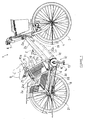
- FIG. 1 is a right side view of the power-assisted bicycle.
- FIG. 2 is a left side view and
- FIG. 3 is a front elevation of the outer box.
- FIG. 4 is a right side view of the inner box.
- FIG. 5 is a right side view of the inner box with its side cover removed.
- FIG. 6 is a left side view of the inner box partially broken away.
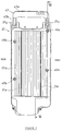
- FIG. 7 is a cross-sectional front elevation of the inner box.
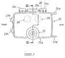
- FIG. 8 is a plan view of the outer box.
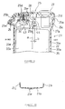
- FIG. 9 is a cross-sectional front elevation of the lid and its vicinity of the outer box.
- FIG. 10 is a cross-sectional plan view of the outer box in two-piece structure. The words "right” and “left” in this embodiment refer to those as seen from the rider.
- a vehicle frame 2 of the bicycle 1 comprises; a front wheel 3 rotatably supported with a front fork 4 which in turn is rotatably supported with a head pipe 2a , a down tube 2b extending from the head pipe 2a obliquely rear downward, a seat tube 2c connected to the lower portion of the down tube 2b through a center lug 5 so as to form a V shape, paired right and left chain stays 2d connected to the lower end of the down tube 2b through a hanger lug 6 , and paired right and left seat stays 2e connected to the upper portion of the seat tube 2c and to the rear end portion of the chain stay 2d , with the seat tube 2c , the chain stays 2d and the seat stays 2e generally forming a triangular form.
- the chain stays 2d and the seat stays 2e are connected through a rear wheel bracket 2f to each other.
- the rear wheel bracket 2f supports a rear wheel 8 for rotation.
- Steering handlebars 7 are attached to the upper end of the front fork 4 .
- a saddle 9 is attached to a seat pillar tube 10 inserted, for extension and contraction, into the upper end of the seat tube 2c .
- the seat pillar tube 10 can be fixed to a required height with a lock handle 11 provided on the upper end of the seat tube 2c .
- the saddle 9 is attached to the end of a bracket 10a secured for rotation to the upper end of the seat pillar tube 10 .
- the saddle 9 may be rotated upward to avoid interference with the battery.
- a power unit 12 is disposed below the center lug 5 .
- the power unit (12) is a device for combining the pedal force inputted from pedals 13 through a crank 14 to a crankshaft 15 with a drive force of an assist drive device 16 and transmitting the combined force to the rear wheel 8 through a chain 58 .
- the assist drive device 16 comprises; an electric motor 17 for outputting the drive force, a battery holding device 18 for holding the battery as a power source for the electric motor 17 , and a controller 19 for controlling the drive force of the electric motor 17 to a value commensurate with the pedal force.
- the electric motor 17 and the controller 19 are disposed under and along the down tube 2b .
- the down tube 2b , the center lug 5 , and the hanger lug 6 are surrounded with an upper cover 20a and a lower cover 20b .
- the battery holding device 18 is disposed behind and along the seat tube 2c in a double case structure in which the battery is held in an inner box 22 which can be freely inserted into or taken out of an outer box 21 .
- Paired right and left flanges 21c are provided in the lower end portion of the front wall 21a of the outer box 21 .
- Paired right and left flanges 21d are provided in the upper end portion of the rear wall 21b of the outer box 21 .
- the flanges 21c and 21d are secured with bolts to a vehicle frame 2 .
- the outer box 21 is made up of right and left pieces of plastic material in a generally rectangular box with an insertion opening 21f on its upper end and with a bottom wall 21g on its lower end, and secured by hook-stopping engagement stop lugs 21e formed on the upper portions of front and rear walls 21a and 21b , and by securing the lower end portion with a bolt 24 .
- the front wall 21a of the outer box 21 is formed with an engagement stop piece 21h extending in tip and down directions for engagement with the seat tube 2c .
- the right and left walls 21i and 21j are formed with a design pattern 21k for improving appearance.
- a charge opening 21m is for inserting a charge plug while the inner box 22 is held in position.
- the front portion of the bottom wall 21g of the outer box 21 is sloped up forward to have a step 21p which is a step higher than the other portion.
- the step portion 21p is for supporting the weight of the inner box 22 .
- the bottom wall 21g is also provided with a male connector 42 constituting part of a connection mechanism 41 for connecting the battery to the drive circuit.
- the male connector 42 is secured to a boss portion formed on the outer surface of the bottom wall 21g with a bolt, with its male terminals 42a projecting toward the inside of the bottom wall 21g , and with the male terminals 42a connected through leads 42b to the electric motor 17 , the controller 19 , and others.
- the upper end of the outer box 21 is provided with a lid 25 for opening and closing the insertion hole 21f .
- the lid 25 is of a dish shape with its periphery having a flange 25a bent downward.
- a boss portion 25b formed on the right side wall of the flange 25a is rotatably supported on the right side of the vehicle with a support pin 26 inserted between boss portions 21n formed at the upper end of the right side wall 21j of the outer box 21 .
- a lock cylinder 27 is secured to the inner left side or toward the end of the lid 25 so as to be engaged with or disengaged from an engagement stop piece 25c formed to project from the inside surface of the flange 25a of the lid 25 by inserting a key switch into the lock cylinder 27 and rotating the engagement claw 27a .
- Each of the urging mechanisms 28 is of a structure in which a slide ring 29 is attached for up and down movement to a guide rod 25d formed to project downward from the inside surface of the lid 25 , and a spring 30 is interposed between a pressing flange 29a of the slide ring 29 and a spring seat 25e of the lid 25 .
- a stopper 31 is for restricting the lowering position of the slide ring 29 and secured with a screw 32 to the lower end surface of the guide rod 25d .
- the inner box 22 is of a structure in which a battery pack 34 is held in a box body 33 .
- the battery pack 34 is of a structure in which a plural number of chargeable unit batteries 36 are connected in series to form a battery group which is disposed in the vehicle width direction in a holding case 35 made up of right and left split pieces of plastic material, and the split pieces are connected together using a pin 34a .
- Discharge leads 37a and charge leads 37b respectively connected to the negative and positive poles of the battery group are routed in lead grooves 35b recess-formed on the outside surface of the holding case 35 and held down with holding claws 35c .
- the charge lead 37b is led up and connected to a charge connection terminal 38 while the discharge lead 37a is led down and connected to a female connector 39 which constitutes part of the connection mechanism 41 .
- the other charge lead 37b is connected to one of the negative and positive poles and is provided with a diode 37c to prevent a short circuit as well as an unauthorized draw current.
- said inner box in addition is provided with a bimetal switch 37d for assuring a correct battery temperature.
- the box body 33 is made up of right and left split pieces, or a bottom case 33a and a lid case 33b , of plastic material.
- the battery pack 34 is received in the bottom case 33a , which is covered with the lid case 33b , and boss portions 33c and 33d are secured with bolts 40a and 40b .
- the boss portions 33c and 33d through which the bolt 40b penetrates also tightens a securing flange 35a formed on the battery pack 34 so that the battery pack 34 is prevented from moving within the box body 33 .
- the bottom case 33a and the lid case 33b of the box body 33 are provided with ribs 33e extending in the up and down directions and coming into contact with the inside surface of the outer box 21 so that the inner box 22 is prevented from moving within the outer box 21 .
- the bottom wall of the box body 33 is formed with a step portion 33f of a height corresponding to the step portion 21p of the outer box 21 so that the step portion 33f is in contact with the step portion 21p in the state of the inner box 22 being held in the outer box 21 and that the weight of the inner box 22 is supported by the step portion 21p and the connection mechanism 41 is protected from being subjected to an excessive load.
- the charge connection terminal 38 is secured with a bolt to the inside surface of the bottom case 33a and faces outside through the opening 33e' of the bottom case 33a so as to be connected to a charge plug of a charger through the charge opening 21m of the outer box 21 .
- the female connector 39 is disposed at a downward projecting portion 33g of the bottom wall of the box body 33 and secured to the bottom case 33a side.
- a female terminal 39a of the female connector 39 faces outside so that the female terminal 39a automatically comes into contact with the male terminal 42a when the inner box 22 is held in the outer box 21 .
- the female and male terminals 39a and 42a are constituted to maintain the contact state even if the inner box 22 vibrates up and down to some extent within the outer box 21 .
- the top wall of the inner box 22 is provided with a handle 43 in a foldable manner.
- the handle 43 is generally of a U shape with its long side portion 43a curved on its both ends to form short side portions 43b .
- the short side portions 43b are supported for swinging with a support pin 44 passed through a boss portion 33g formed on the top wall of the box body 33 .
- the support pin 44 is displaced by a distance b toward the left from the width center line a of the inner box 22 .
- the height of the handle 43 is set so that, when the handle 43 is folded, the end of the long side portion 43a is flush with the right side surface of the inner box 22 (Refer to the dash-and-double-dotted phantom lines in FIG. 7).
- the inner box 22 is pressed by the urging mechanism 28 through the handle 43 .
- the inner box 22 When the charging is over, the inner box 22 may be inserted into the outer box 21 through the insertion opening 21f . Then, the female connector 39 disposed on the bottom surface of the inner box 22 is automatically connected to the male connector 42 disposed on the bottom surface of the outer box 21 . The weight of the inner box 22 is supported by the contact between the step portion 21p of the outer box 21 and the step portion 33f of the inner box 22 so that the male and female connectors 42 and 38 are protected from being subjected to an excessive load.
- the projecting portion 33g located lower than the step portion 33f of the bottom wall of the inner box 22 butts against th step portion 21p of the outer box 21 so that the insertion error is immediately noticed.
- the handle 43 is displaced from the center line a of the inner box 22 and the height of the handle 43 is set so that its end is flush with the side surface of the inner box 22 .
- the handle 43 may also be urged by a spring or the like to return the handle 43 to the normal position.
- the inner box holding a battery is held, to be freely taken out, in the outer box, effects are obtained that the inner box may be removed from the vehicle when charging the battery to facilitate handling for charging. Furthermore, since the connection mechanism is provided within the outer box with the lid, the connection mechanism is not exposed outside even when the inner box is removed so that the electric connection function is prevented from deteriorating due to exposure to the elements and damages due to tampering is avoided.
- the handle since the handle is disposed on the top wall of the inner box, the inner box can be easily inserted into and taken out of the outer box. Furthermore, since the handle is made foldable, the size of the outer box is prevented from increasing due to the space for stowing the handle.
- Still another effect is that, when the lid is closed, the urging mechanism presses the folded handle, and the handle presses the inner box so that both the inner box and the handle are mechanically secured with a single urging mechanism, and noise due to vibration of the inner box or the handle is prevented.
Applications Claiming Priority (2)
| Application Number | Priority Date | Filing Date | Title |
|---|---|---|---|
| JP35573/95 | 1995-02-23 | ||
| JP03557395A JP3491708B2 (ja) | 1995-02-23 | 1995-02-23 | 電動自転車用バッテリ収納装置 |
Publications (2)
| Publication Number | Publication Date |
|---|---|
| EP0728662A2 true EP0728662A2 (de) | 1996-08-28 |
| EP0728662A3 EP0728662A3 (de) | 1998-03-18 |
Family
ID=12445510
Family Applications (1)
| Application Number | Title | Priority Date | Filing Date |
|---|---|---|---|
| EP96102771A Withdrawn EP0728662A3 (de) | 1995-02-23 | 1996-02-23 | Batteriehalterung für ein Fahrzeug |
Country Status (4)
| Country | Link |
|---|---|
| US (1) | US5789898A (de) |
| EP (1) | EP0728662A3 (de) |
| JP (2) | JP3491708B2 (de) |
| CN (1) | CN1104345C (de) |
Cited By (10)
| Publication number | Priority date | Publication date | Assignee | Title |
|---|---|---|---|---|
| US6148944A (en) * | 1997-09-16 | 2000-11-21 | Sanyo Electric Co., Ltd. | Electrically driven bicycle |
| FR2794289A1 (fr) * | 1999-05-25 | 2000-12-01 | Honda Motor Co Ltd | Dispositif d'echange de batteries |
| CN1101764C (zh) * | 1996-10-23 | 2003-02-19 | 本田技研工业株式会社 | 电动辅助自行车上的电池安放构造 |
| EP1188659A3 (de) * | 2000-09-14 | 2005-04-20 | Honda Giken Kogyo Kabushiki Kaisha | Batteriekasten- Montageanordnung für Fahrrad [1999/13] |
| CN103358872A (zh) * | 2012-03-30 | 2013-10-23 | 本田技研工业株式会社 | 跨骑式电动车辆 |
| JP2014206755A (ja) * | 2014-07-15 | 2014-10-30 | カシオ計算機株式会社 | 防水蓋装置、及び電子機器 |
| CN104578274A (zh) * | 2014-12-25 | 2015-04-29 | 贵阳丰久昌信息技术有限公司 | 一种电动车 |
| EP2868565A4 (de) * | 2012-06-29 | 2015-07-15 | Panasonic Ip Man Co Ltd | Batteriemontagevorrichtung und elektrisches fahrrad |
| CN110733362A (zh) * | 2018-07-20 | 2020-01-31 | 美达系统有限公司 | 电动或混合动力机动车的电池充电器 |
| EP3660942A1 (de) | 2018-11-28 | 2020-06-03 | BMZ Batterie-Montage-Zentrum GmbH | Energiespeicher, der an einem transportvehikel wie einem lastenfahrrad, einer sackkarre oder dergleichen anbaubar ist, und akkumulator hierfür |
Families Citing this family (48)
| Publication number | Priority date | Publication date | Assignee | Title |
|---|---|---|---|---|
| JP3622020B2 (ja) * | 1996-07-31 | 2005-02-23 | ヤマハ発動機株式会社 | 電動自転車のバッテリボックス脱着構造 |
| JPH11124071A (ja) * | 1997-10-22 | 1999-05-11 | Suzuki Motor Corp | 電動補助自転車 |
| CN103448849A (zh) * | 1997-11-17 | 2013-12-18 | 吴正德 | 一种车架 |
| JP3929243B2 (ja) * | 1998-10-15 | 2007-06-13 | ヤマハ発動機株式会社 | 電動車両用電源システム |
| WO2000038944A1 (fr) * | 1998-12-28 | 2000-07-06 | Yamaha Hatsudoki Kabushiki Kaisha | Systeme d'alimentation electrique pour un vehicule |
| JP4277968B2 (ja) * | 1999-05-25 | 2009-06-10 | 本田技研工業株式会社 | 電動補助自転車のバッテリ取付構造 |
| JP4492905B2 (ja) * | 2001-03-19 | 2010-06-30 | 本田技研工業株式会社 | 電動補助自転車 |
| JP4274759B2 (ja) * | 2002-08-16 | 2009-06-10 | ヤマハ発動機株式会社 | 電動二輪車 |
| AU2004207820B2 (en) * | 2003-01-28 | 2009-09-17 | Club Car, Inc. | Housing for vehicle power systems |
| US20050224306A1 (en) * | 2004-03-15 | 2005-10-13 | Kosco James M | Latch assembly for vehicle power supply |
| US7267352B2 (en) * | 2005-02-18 | 2007-09-11 | Shimano, Inc. | Apparatus for mounting an electrical component to a bicycle |
| JP2007015641A (ja) * | 2005-07-11 | 2007-01-25 | Yamaha Motor Co Ltd | 電動自転車 |
| JP5041755B2 (ja) * | 2006-07-28 | 2012-10-03 | 三洋電機株式会社 | パック電池 |
| US7614469B2 (en) * | 2007-05-07 | 2009-11-10 | General Electric Company | Battery case and method for securing same |
| US7836990B2 (en) * | 2007-06-26 | 2010-11-23 | Honda Motor Company, Ltd. | Battery boxes having aperture and vehicles including same |
| US7836989B2 (en) * | 2007-06-26 | 2010-11-23 | Honda Motor Company, Ltd. | Battery boxes and vehicles including same |
| TWM331487U (en) * | 2007-11-09 | 2008-05-01 | Ideal Bike Corp | Tube connector combined with electric power for connection of frame tubes |
| US8067848B1 (en) * | 2008-01-14 | 2011-11-29 | Lixon Vilsaint | Bicycle adapter mobile telephone charger |
| CH701675B1 (de) * | 2009-08-20 | 2014-09-15 | Fairly Bike Mfg Co Ltd | Batteriehalterung. |
| KR101182427B1 (ko) * | 2009-12-21 | 2012-09-12 | 에스비리모티브 주식회사 | 배터리 팩 및 이를 구비하는 자동차 |
| JP5502529B2 (ja) * | 2010-03-01 | 2014-05-28 | 三洋電機株式会社 | 電動補助自転車 |
| US8469381B2 (en) * | 2010-08-26 | 2013-06-25 | Cycling Sports Group, Inc. | Bicycle |
| KR101175024B1 (ko) | 2010-12-16 | 2012-08-17 | 삼성에스디아이 주식회사 | 전기 자전거용 전원 공급장치 |
| US8893837B2 (en) * | 2011-06-14 | 2014-11-25 | Samsung Sdi Co., Ltd. | Battery pack storing device and electric vehicle including the same |
| AU2012330172B2 (en) * | 2011-10-26 | 2015-07-16 | Honda Motor Co., Ltd. | Electric vehicle |
| JP5894814B2 (ja) * | 2012-02-20 | 2016-03-30 | 本田技研工業株式会社 | 電動車両用電源装置 |
| JP5919065B2 (ja) * | 2012-03-30 | 2016-05-18 | 本田技研工業株式会社 | 電動車両における円柱型バッテリの搭載構造 |
| EP2898404A4 (de) | 2012-09-21 | 2016-05-25 | Civilized Cycles Inc | Vielseitige elektrofahrradsysteme |
| US10611425B2 (en) | 2013-11-06 | 2020-04-07 | Yamaha Hatsudoki Kabushiki Kaisha | Saddle-type electric vehicle |
| JP6203655B2 (ja) * | 2014-02-12 | 2017-09-27 | ブリヂストンサイクル株式会社 | 電動アシスト自転車のバッテリーボックス |
| CN104097723B (zh) * | 2014-06-23 | 2017-10-03 | 苏州达方电子有限公司 | 适用于电动脚踏车的车架 |
| US9676443B2 (en) * | 2015-03-02 | 2017-06-13 | Ford Global Technologies, Llc | Removable powerpack and seat for a bicycle |
| USD764411S1 (en) | 2015-03-09 | 2016-08-23 | Pacific Storm, Inc. | Bike battery box |
| CN106684270B (zh) * | 2015-11-06 | 2021-07-06 | 光阳工业股份有限公司 | 摩托车电池盒构造 |
| DE102016213903B3 (de) * | 2016-07-28 | 2018-01-11 | Robert Bosch Gmbh | Halteelement zur Verwendung an einem Akkumulator sowie zugehörige Haltevorrichtung |
| CN106549130B (zh) * | 2016-10-14 | 2019-01-25 | 浙江中力机械有限公司 | 插拔组件及具有插拔组件的插拔式电池 |
| USD829131S1 (en) | 2016-12-14 | 2018-09-25 | Civilized Cycles Incorporated | Bicycle with panniers |
| WO2019064606A1 (ja) | 2017-09-29 | 2019-04-04 | 本田技研工業株式会社 | 車両のバッテリ収納装置 |
| CN108001578A (zh) * | 2017-12-29 | 2018-05-08 | 江苏爱玛车业科技有限公司 | 载物座及电动车 |
| TWM562237U (zh) * | 2018-03-01 | 2018-06-21 | Kwang Yang Motor Co | 電動車的電池結構 |
| CN108583769A (zh) * | 2018-04-26 | 2018-09-28 | 海宁市海创通日用品科技有限公司 | 新能源电瓶车接电方法 |
| ES2957311T3 (es) | 2018-05-07 | 2024-01-17 | Trek Bicycle Corp | Conjunto de batería de bicicleta |
| CN108995521B (zh) * | 2018-07-25 | 2020-07-07 | 吴玉挺 | 一种利用咬紧实现电动车电池固定的剪力型电池支撑机构 |
| JP7095103B2 (ja) * | 2018-09-27 | 2022-07-04 | 本田技研工業株式会社 | 鞍乗型車両のバッテリ着脱構造 |
| CN110474003A (zh) * | 2019-08-16 | 2019-11-19 | 四川九洲电器集团有限责任公司 | 一种电池盒 |
| US20210178914A1 (en) * | 2019-12-11 | 2021-06-17 | Lyft, Inc. | Modular bicycle designs |
| USD932380S1 (en) * | 2020-01-24 | 2021-10-05 | Super 73, Inc. | Motorbike power source enclosure |
| TWI787105B (zh) * | 2022-03-24 | 2022-12-11 | 達方電子股份有限公司 | 電動自行車 |
Citations (2)
| Publication number | Priority date | Publication date | Assignee | Title |
|---|---|---|---|---|
| GB2011328A (en) * | 1977-12-28 | 1979-07-11 | Deutsche Automobilgesellsch | Apparatus for reveiving an exchageable energy storage means in a motor vehicle |
| JPH05319104A (ja) * | 1992-05-26 | 1993-12-03 | Yamaha Motor Co Ltd | 電動自転車用バッテリーケースの取付構造 |
Family Cites Families (6)
| Publication number | Priority date | Publication date | Assignee | Title |
|---|---|---|---|---|
| GB1530132A (en) * | 1975-01-21 | 1978-10-25 | Lucas Industries Ltd | Electrically assisted cycle |
| US4077485A (en) * | 1975-12-31 | 1978-03-07 | Bolt Vehicles, Incorporated | Vehicle battery mounting apparatus |
| JPH0334048Y2 (de) * | 1985-03-01 | 1991-07-18 | ||
| US4710693A (en) * | 1987-04-17 | 1987-12-01 | Wigell Arthur H | Front loading continuous charger |
| US5477936A (en) * | 1991-10-19 | 1995-12-26 | Honda Giken Kogyo Kabushiki Kaisha | Electric motor vehicle and battery unit for electric motor vehicle |
| IT229554Y1 (it) * | 1993-01-14 | 1999-01-29 | Perego Pines Gmbh | Perfezionamento all'impiego di accumulatori su veicolo elettrico per bambini |
-
1995
- 1995-02-23 JP JP03557395A patent/JP3491708B2/ja not_active Expired - Fee Related
-
1996
- 1996-02-17 CN CN96103549A patent/CN1104345C/zh not_active Expired - Fee Related
- 1996-02-23 US US08/606,074 patent/US5789898A/en not_active Expired - Fee Related
- 1996-02-23 EP EP96102771A patent/EP0728662A3/de not_active Withdrawn
- 1996-04-30 JP JP10909196A patent/JP3491723B2/ja not_active Expired - Fee Related
Patent Citations (2)
| Publication number | Priority date | Publication date | Assignee | Title |
|---|---|---|---|---|
| GB2011328A (en) * | 1977-12-28 | 1979-07-11 | Deutsche Automobilgesellsch | Apparatus for reveiving an exchageable energy storage means in a motor vehicle |
| JPH05319104A (ja) * | 1992-05-26 | 1993-12-03 | Yamaha Motor Co Ltd | 電動自転車用バッテリーケースの取付構造 |
Non-Patent Citations (1)
| Title |
|---|
| PATENT ABSTRACTS OF JAPAN vol. 018, no. 136 (M-1572), 7 March 1994 & JP 05 319104 A (YAMAHA MOTOR CO LTD), 3 December 1993, * |
Cited By (11)
| Publication number | Priority date | Publication date | Assignee | Title |
|---|---|---|---|---|
| CN1101764C (zh) * | 1996-10-23 | 2003-02-19 | 本田技研工业株式会社 | 电动辅助自行车上的电池安放构造 |
| US6148944A (en) * | 1997-09-16 | 2000-11-21 | Sanyo Electric Co., Ltd. | Electrically driven bicycle |
| FR2794289A1 (fr) * | 1999-05-25 | 2000-12-01 | Honda Motor Co Ltd | Dispositif d'echange de batteries |
| EP1188659A3 (de) * | 2000-09-14 | 2005-04-20 | Honda Giken Kogyo Kabushiki Kaisha | Batteriekasten- Montageanordnung für Fahrrad [1999/13] |
| CN103358872A (zh) * | 2012-03-30 | 2013-10-23 | 本田技研工业株式会社 | 跨骑式电动车辆 |
| CN103358872B (zh) * | 2012-03-30 | 2016-03-09 | 本田技研工业株式会社 | 跨骑式电动车辆 |
| EP2868565A4 (de) * | 2012-06-29 | 2015-07-15 | Panasonic Ip Man Co Ltd | Batteriemontagevorrichtung und elektrisches fahrrad |
| JP2014206755A (ja) * | 2014-07-15 | 2014-10-30 | カシオ計算機株式会社 | 防水蓋装置、及び電子機器 |
| CN104578274A (zh) * | 2014-12-25 | 2015-04-29 | 贵阳丰久昌信息技术有限公司 | 一种电动车 |
| CN110733362A (zh) * | 2018-07-20 | 2020-01-31 | 美达系统有限公司 | 电动或混合动力机动车的电池充电器 |
| EP3660942A1 (de) | 2018-11-28 | 2020-06-03 | BMZ Batterie-Montage-Zentrum GmbH | Energiespeicher, der an einem transportvehikel wie einem lastenfahrrad, einer sackkarre oder dergleichen anbaubar ist, und akkumulator hierfür |
Also Published As
| Publication number | Publication date |
|---|---|
| JPH08230490A (ja) | 1996-09-10 |
| JPH08258770A (ja) | 1996-10-08 |
| JP3491708B2 (ja) | 2004-01-26 |
| US5789898A (en) | 1998-08-04 |
| CN1104345C (zh) | 2003-04-02 |
| JP3491723B2 (ja) | 2004-01-26 |
| CN1142446A (zh) | 1997-02-12 |
| EP0728662A3 (de) | 1998-03-18 |
Similar Documents
| Publication | Publication Date | Title |
|---|---|---|
| EP0728662A2 (de) | Batteriehalterung für ein Fahrzeug | |
| EP0712779B1 (de) | Batteriehalterungsstruktur | |
| EP0686550B1 (de) | Anordnung zum Ein- und Ausbau von Batterien in Fahrrädern mit Hilfsmotor | |
| US5545046A (en) | Charging connector for electric vehicle | |
| JP3386665B2 (ja) | 電動自転車用バッテリーケースの取付構造 | |
| JPH0911759A (ja) | 車両用バッテリ収納装置 | |
| EP0648633A1 (de) | Abdeckung und Behälter zur Aufnahme der Batterie eines Elektrofahrzeuges | |
| US20040031632A1 (en) | Battery mounting arrangement for electrically powered vehicle | |
| EP0686522A2 (de) | Vorrichtung für den Ein- und Ausbau einer Batterie für ein Fahrrad mit Hilfsmotor | |
| EP1188659B1 (de) | Fahrrad mit Hilfsmotor und einem Behälter zur Aufnahme einer Batterie | |
| EP2626231B1 (de) | Stromversorgungsvorrichtung für ein elektrisches Fahrzeug | |
| EP0686551B1 (de) | Verkleidung von Fahrrädern mit Hilfsmotor | |
| JP4113756B2 (ja) | 電源供給ボックス | |
| JP3617678B2 (ja) | 電動自転車 | |
| JP3336529B2 (ja) | 電動スクータ | |
| TWI676569B (zh) | 跨騎型車輛 | |
| EP0686549A1 (de) | Anordnung des Steckers zum Aufladen der Batterien von Fahrrädern mit Hilfsmotor | |
| JP2020142771A (ja) | 電動車両のバッテリ端子構造 | |
| JPH08207877A (ja) | 電動2輪車のバッテリケース取付構造 | |
| JP3436378B2 (ja) | 電動自転車用バッテリーケース | |
| WO2023008041A1 (ja) | 充電コネクタ | |
| EP2796354A1 (de) | Elektrisches sattelfahrzeug | |
| EP2796353B1 (de) | Elektrisches sattelfahrzeug | |
| JP5425001B2 (ja) | 自動車充電装置 | |
| JP3494257B2 (ja) | 電動自転車用バッテリ収納装置 |
Legal Events
| Date | Code | Title | Description |
|---|---|---|---|
| PUAI | Public reference made under article 153(3) epc to a published international application that has entered the european phase |
Free format text: ORIGINAL CODE: 0009012 |
|
| AK | Designated contracting states |
Kind code of ref document: A2 Designated state(s): DE FR IT |
|
| PUAL | Search report despatched |
Free format text: ORIGINAL CODE: 0009013 |
|
| RHK1 | Main classification (correction) |
Ipc: B62M 23/02 |
|
| AK | Designated contracting states |
Kind code of ref document: A3 Designated state(s): DE FR IT |
|
| 17P | Request for examination filed |
Effective date: 19980915 |
|
| 17Q | First examination report despatched |
Effective date: 20010801 |
|
| GRAP | Despatch of communication of intention to grant a patent |
Free format text: ORIGINAL CODE: EPIDOSNIGR1 |
|
| STAA | Information on the status of an ep patent application or granted ep patent |
Free format text: STATUS: THE APPLICATION IS DEEMED TO BE WITHDRAWN |
|
| 18D | Application deemed to be withdrawn |
Effective date: 20040415 |