EP0724229B1 - Bildverarbeitungsvorrichtung und Verfahren - Google Patents
Bildverarbeitungsvorrichtung und Verfahren Download PDFInfo
- Publication number
- EP0724229B1 EP0724229B1 EP95309438A EP95309438A EP0724229B1 EP 0724229 B1 EP0724229 B1 EP 0724229B1 EP 95309438 A EP95309438 A EP 95309438A EP 95309438 A EP95309438 A EP 95309438A EP 0724229 B1 EP0724229 B1 EP 0724229B1
- Authority
- EP
- European Patent Office
- Prior art keywords
- image
- segment
- area
- color
- data
- Prior art date
- Legal status (The legal status is an assumption and is not a legal conclusion. Google has not performed a legal analysis and makes no representation as to the accuracy of the status listed.)
- Expired - Lifetime
Links
Images


Classifications
-
- G—PHYSICS
- G06—COMPUTING; CALCULATING OR COUNTING
- G06T—IMAGE DATA PROCESSING OR GENERATION, IN GENERAL
- G06T3/00—Geometric image transformation in the plane of the image
- G06T3/40—Scaling the whole image or part thereof
-
- G—PHYSICS
- G06—COMPUTING; CALCULATING OR COUNTING
- G06T—IMAGE DATA PROCESSING OR GENERATION, IN GENERAL
- G06T7/00—Image analysis
- G06T7/10—Segmentation; Edge detection
- G06T7/11—Region-based segmentation
-
- G—PHYSICS
- G06—COMPUTING; CALCULATING OR COUNTING
- G06T—IMAGE DATA PROCESSING OR GENERATION, IN GENERAL
- G06T7/00—Image analysis
- G06T7/10—Segmentation; Edge detection
- G06T7/194—Segmentation; Edge detection involving foreground-background segmentation
-
- G—PHYSICS
- G06—COMPUTING; CALCULATING OR COUNTING
- G06V—IMAGE OR VIDEO RECOGNITION OR UNDERSTANDING
- G06V10/00—Arrangements for image or video recognition or understanding
- G06V10/40—Extraction of image or video features
- G06V10/56—Extraction of image or video features relating to colour
-
- G—PHYSICS
- G06—COMPUTING; CALCULATING OR COUNTING
- G06V—IMAGE OR VIDEO RECOGNITION OR UNDERSTANDING
- G06V30/00—Character recognition; Recognising digital ink; Document-oriented image-based pattern recognition
- G06V30/40—Document-oriented image-based pattern recognition
- G06V30/41—Analysis of document content
- G06V30/414—Extracting the geometrical structure, e.g. layout tree; Block segmentation, e.g. bounding boxes for graphics or text
-
- G—PHYSICS
- G06—COMPUTING; CALCULATING OR COUNTING
- G06T—IMAGE DATA PROCESSING OR GENERATION, IN GENERAL
- G06T2207/00—Indexing scheme for image analysis or image enhancement
- G06T2207/10—Image acquisition modality
- G06T2207/10004—Still image; Photographic image
- G06T2207/10008—Still image; Photographic image from scanner, fax or copier
-
- G—PHYSICS
- G06—COMPUTING; CALCULATING OR COUNTING
- G06T—IMAGE DATA PROCESSING OR GENERATION, IN GENERAL
- G06T2207/00—Indexing scheme for image analysis or image enhancement
- G06T2207/30—Subject of image; Context of image processing
- G06T2207/30176—Document
Definitions
- This invention relates to an image processing apparatus and method. More particularly, the invention relates to an image processing method and apparatus for extracting image segments having different characteristics from an input color image and judging each of the characteristics of these image segments.
- Apparatuses for inputting and outputting color images have begun to find wider use in the field of office automation. This has been accompanied by greater opportunities for handling color images obtained by using an input device such as a scanner to read in an original of a color image the greater part of which is occupied by a black-and-white portion or a portion wherein the number of colors is limited. Such a color image shall be referred to as a "document image”.
- a feature of a document image is that, unlike other images, a document image includes a mixture of image segments (such as character image segments and photographic image segments) having different properties.
- EP-A-0 516 576 describes a method wherein text and graphics in a document are discriminated by extracting the contours of black and white objects from a (filtered) input image, determining the shape properties of each object from said extracted contours, evaluating the inclusion relationship between the objects, and classifying each object as either text, graphics or white background on the basis of said determined shape properties and inclusion relationship.
- the original image is combined with (masks of) the classified objects to separately generate text and graphics, whereby different objects represented in the input image by black pixels can be colour-coded. It thus appears that this prior art method can not handle complicated color images wherein the background is not exclusively white.
- Methods of zooming an image include selective processing conversion (SPC), in which each pixel of an original image is eliminated periodically in dependence upon the zoom ratio (this is image reduction) or in which each pixel is repeated in dependence upon the zoom ratio (this is image enlargement) (see Matsumoto, Kobayashi: “Study on the Effect of the Resolution Conversion on Picture Quality", The Journal of the Institute of Image Electronics Engineers of Japan, Vol. 12, No. 5, pp. 354 - 362, 1983), and a method of obtaining the value of a pixel of interest by interpolation from neighboring pixels following a coordinate transformation (an affine transformation, etc.).
- SPC selective processing conversion
- a method proposed by the present applicant is available as a method of zooming a binary image.
- This method relates to an apparatus for extracting, smoothing and zooming outline information of a binary image and involves extracting outline vectors from a binary image, creating outline vectors that have been zoomed smoothly to a desired magnification (arbitrary) in the state of the extracted outline vector expression, and reproducing the binary image from the smoothing zoomed outline vectors, thereby obtaining a high-quality digital image zoomed to the desired magnification (arbitrary).
- An example of an available method of reducing the quantity of image data when the image is stored or communicated is a coding method using a discrete cosine transform (DCT) according to the Joint Photographic Experts Group (JPEG).
- DCT discrete cosine transform
- JPEG Joint Photographic Experts Group
- a color image is converted to a uniform color space, after which the image is split up using color difference.
- the shape of an segment is subjected to chain coding, hue is quantized coarsely segment by segment using stored colors, saturation is subjected to a polynomial approximation and lightness is subjected to adaptive DCT coding, whereby the image data is coded.
- JBIG Joint Bi-Level Image Group
- An example of a method of segmenting a color image is a recursive threshold-value method (see “Structuring of Color Image Information by Area Partition Processing", Journal of Information Processing Society of Japan, Vol. 19, No. 12, pp. 1130 - 1136, Dec. 1987).
- processing for deciding a threshold value for area partitioning from the value of a histogram in RGB, HSI, YIQ color features and then extracting an area is repeated recursively with regard to each extracted area.
- Another reported method is the limited-color expression method.
- This utilizes a color quantizing technique in which a color distribution is partitioned repeatedly until attainment of a number of colors in which a color error cannot be visually recognized by the human eye (see The Institute of Electronics, Information and Communication Engineers, 1990, Spring, All-Japan Convention, D146 7-168).
- Examples of a method of segmenting image segments applied to a document image is one in which areas are judged pixel by pixel using the information possessed by neighboring pixels (see Tetsuya, Ochi: "Bilevel Rendition Method for Documents Including Gray-Scale and Bilevel Image", The Transactions of the Institute of Electronic and Communication Engineers, Vol. J67-B, No. 7, pp.
- the image is divided into a number of blocks and, in a first image scan, thresholds T1 and T2 are established for each block according to local block conditions; in a second image scan, each block is labelled as either bilevel or multilevel, as well as either monochrome or polychrome.
- the SPC zoom method is capable of forming a zoomed image in simple fashion but problems such as jaggies arise in terms of image quality.
- a zoom method using coordinate transformation is effective for natural images, such as images of scenery.
- this method is applied to document images, the edges of character or line drawing portions such as characters and graphs become blurred owing to interpolation processing.
- the method of zooming a binary image proposed by the present applicant is very effective as a method of extracting, smoothing and zooming the outline information of a binary image.
- this method cannot be applied directly to zooming of a color image or grayscale image.
- the method of reducing the quantity of data by coding using a DCT is effective for a natural image.
- image quality deteriorates markedly at character or line-drawing portions such as characters and graphs.
- the method of segmentation and coding a segment also is for application to natural images and lightness is therefore subjected to adaptive DCT coding.
- the lightness information comes to occupy a major part of the total quantity of information. Accordingly, this method is useful with regard to continuous tone portions of a color image.
- coding efficiency is poor with regard to documents, in which black-and-white portions or limited-color portions occupy the major part of the document and the importance of lightness information is low.
- the coding method based upon MR/MMR or JBIG is effective when reducing the amount of data in a binary image.
- this method cannot be applied directly when reducing the amount of data in a color image or grayscale image.
- the method of image segmentation using the recursive threshold-value method or limited-color expression method can be applied to portion segmenting of a natural image.
- the method cannot be applied directly to a document image having image segments whose properties differ from those of a natural image (because the definition of a character segment is different from that of a natural image).
- the image segmentation method for application to a character image is for the purpose of processing a binary image or a grayscale image. It is difficult to apply this method to a color image in which there is much overlapping of image segments.
- the proposed zoom method, data reducing method and image segmentation method are often suitable for natural images but satisfactory results cannot be expected when these methods are applied to a document image.
- the proposed methods for application to document images are suitable for binary images and grayscale images but cannot be applied directly to color images.
- a concern of the present invention is to solve the aforementioned problems and provide an image processing apparatus and method as set out in the appended claims in which excellent processing is applied to a color image in which image segments having different characteristics are mixed.
- an image processing method comprising an input step of inputting a color image, an extraction step of extracting image segments, which have characteristics different from a background image segment of the inputted color image, from the color image, and a discrimination step of discriminating the characteristics of each image segment extracted at the extraction step.
- the invention further discloses an image processing method for extracting each image segment from a color image in which image segments having different components are mixed, comprising a creation step of creating a reduced image from an input color image, a first extraction step of extracting an image segment from the reduced image, and a second extraction step of extracting an image segment from the input color image using data of the image segment extracted at the first extraction step.
- the invention further discloses an image processing apparatus comprising input means for inputting a color image, extraction means for extracting image segments, which have characteristics different from a background image segment of the input color image, from the color image, and discrimination means for discriminating the characteristics of each image segment extracted by the extraction means.
- the invention further discloses an image processing apparatus for extracting each image segment from a color image in which image segments having different components are mixed, comprising creation means for creating a reduced image from an input color image, first extraction means for extracting an image segment from the reduced image, and second extraction means for extracting an image segment from the input color image using data of the image segment extracted by the first extraction means.
- a color document image in which image segments having different components (segmentation components) are mixed undergoes image-segment extraction and discrimination of components.
- An "image-segment” is a linked portion having the same characteristic in an image.
- An image-segmentation component indicates the properties of an image segment, such as whether an image segment is one comprising a character or a line drawing, one comprising a photograph or one which is a color image segment. Examples of image-segment components are described below. Specifically, an image segment of a document image is described as having any of the following image-segment components, for example: a "continuous color tone”, a "limited-color character or line drawing", a “limited-color pseudo-halftone”, a “continuous monochromatic tone” a "limited-value character or line drawing” and a "limited-value pseudo-halftone". Though the details of these image-segment components will be set forth below, it is of course possible to use image-segment components based upon a simpler or more detailed classification.
- An image segment having an image-segment component in a document image is considered to be one delimited by the background.
- image segments can be extracted by partitioning an input image at portions delimited by the background.
- a black-and-white original generally has a "white" background color
- the background color of a color original is not necessarily white.
- a certain background often is overlapped by backgrounds of other colors. Accordingly, in the present invention, extraction of background and the partitioning of image segments based upon the background are repeated recursively with respect to image segments (initially the input image), whereby segmentation of images areas is achieved.
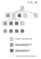
- Fig. 1 is a diagram showing a procedure for segmenting image segments according to the present invention.
- a background 5002 is extracted from an input image 5001, then image segments 5003 and 5004, which can be segmented using the background 5002, are extracted. Since no further extraction of background can be performed with regard to the image segment 5003, segmentation of image segments is concluded for this image segment. With regard to area 5004, however, a background 5005 can be extracted and image segmentation is continued for this image segment. Image-segment components are discriminated with regard to each image segment thus segmented from the input image.
- An image segment indicative of background shall be referred to as a "background image segment”, and an image segment indicative of something other than background shall be referred to as a "general image segment”.
- an image segment currently being processed namely an image segment containing an image segment for which judgment as to whether or not it includes background is incomplete and an image segment containing a plurality of image segments shall be referred to as an "intermediate image segment”, and an image segment (inclusive of a background image segment) for which partitioning processing has been completed shall be referred to as a "final image segment”.
- an input image is also an intermediate image segment.
- the image processing apparatus and method described below can be utilized in pixel-density conversion or zoomed output in a device, such as a color printer, which handles a color document image, in pixel-density conversion at the time of enlargement/reduction and output in a DTP system, and in pixel-density conversion and zoomed output in a color facsimile. Further, the image processing apparatus and method can be utilized in reducing quantity of data at the time of image communication in a color facsimile or in the network equipment of a LAN or the like, and when storing a color image in a storage device such as a magnetic disk device.
- Fig. 2 is a diagram showing a processing procedure for a case in which the present invention is applied to color image zoom processing in an image processing apparatus.
- a digital color image to be processed is inputted at a color image input step 1 and image segments are extracted from the input color image at an image-segment extraction step 2, thereby creating data representing the extracted image segments (this data shall be referred to as "image-segment data").
- image-segment data this data shall be referred to as "image-segment data"
- each extracted image segment is discriminated for image-segment components at an image-segment discrimination step 3 and each extracted image segment is subjected to zoom processing conforming to the discriminated image-segment component at an adaptive zooming step 4, thereby creating a zoomed image of the input image.
- the created zoomed image is displayed, outputted as a hard copy or outputted to a communication line.
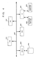
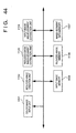
- Fig. 3 is a block diagram showing the construction of an image processing apparatus which executes the processing shown in Fig. 2, and Fig. 4 is a block diagram showing hardware for implementing the arrangement of Fig. 3.
- the hardware shown in Fig. 4 will be described first.
- the hardware includes a CPU 2001, a bus 2007 for interconnecting the CPU 2001 and other components mentioned below, a ROM 2004 in which programs executed by the CPU and data are stored in advance, a RAM 2006 utilized as the working memory of the CPU 2001, a storage device 2002 such as a hard disk or magneto-optical disk for storing programs and image data, a disk input/output unit 2003 for data input/output with respect to the storage device 2002, a color image input unit 2008, a color image output unit 2009, and an input/output port 2005 for input/output of data with respect to the color image input/output units 2008, 2009.
- the CPU 2001 controls each of the aforementioned components via the bus 2007 and provides the color image output unit 2009 with results obtained by applying processing to color image data inputted from the color image input unit 2008 or color image data stored in the storage device 2002, wherein the RAM 2006 is used as a working area.
- a color image input unit 1001 inputs digital color image data to be processed and stores this data in an input image memory 1006. Under the control of the CPU 2001 which operates in accordance with the program stored in the ROM 2004 or storage device 2002, the color image input unit 1001 inputs the color image data using the color image output unit 2009 and stores the color image data in the RAM 2006 or storage device 2002. It should be noted that the color image input unit 1001 may be an input unit for reading in an image by a color image scanner, an input unit which receives color image data from a communication line, an input unit for reading in color image data that has been stored in an image storage device or a combination of these input units.
- An image-segment extraction unit 1002 extracts image segments from the image that has been stored in an input image memory 1006 and stores the extracted image-segment data in an image-segment data memory 1007.
- An image-segment discrimination unit 1003 discriminates image-segment components in each image segment extracted by the image-segment extraction unit 1002 and stores the image-segment components in the image-segment data memory 1007.
- An adaptive zoom unit 1004 subjects each image segment extracted by the image-segment extraction unit 1002 to zoom processing conforming to the image-segment component discriminated by the image-segment discrimination unit 1003, thereby creating an image obtained by zooming the input image, and stores the image data representing the zoomed image in a zoomed-image memory 1008. It should be noted that information indicating the attribute of each image segment is stored in the image-segment data memory 1007.
- the image-segment extraction unit 1002, image-segment discrimination unit 1003 and adaptive zoom unit 1004 can be constructed by the CPU 2001, which operates in accordance with the program stored in the ROM 2004 or storage device 2002, and the RAM 2006 used as the working area or the storage device 2002. It goes without saying that the units 1002, 1003 and 1004 may also be constructed of there own CPUs, RAMs and storage devices and may be implemented by their own hardware.
- a color image output unit 1005 outputs the zoomed image data created by the adaptive zoom unit 1004 and stored in the zoomed-image memory 1008.
- the destination of this output is a display, a printer or copier for making hard copies, a communication line or an image storage device.
- An arrangement can be adopted in which, under the control of the CPU 2001 which operates in accordance with the program stored in the ROM 2004 or storage device 2002, the color image output unit 1005 outputs the zoomed image data, which has been stored in the RAM 2006 or storage device 2002, to the color image output unit 2009.
- the input image memory 1006, the image-segment data memory 1007 and the zoomed-image memory 1008 can also be realized by the RAM 2006 or storage device 2002. It goes without saying that these memories can be realized by their own storage devices.
- image segments are extracted from the color image that has been stored in the input image memory 1006 at the color image input step 1, data representing the extracted image segment is created and the data is stored in the image-segment data memory 1007.
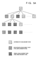
- Fig. 5A is a diagram showing an overview of the image-segment data.
- the image-segment data expresses a group of image segments in an input image by a tree structure in which each image segment is adopted as a node.
- the parent-child relationship of the tree structure represents the image-segment inclusion relationship.
- a node representing an intermediate image segment has child nodes which represent one background image segment and several intermediate image segments or general image segments contained in an intermediate image segment.
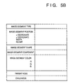
- Fig. 5B is a diagram illustrating items of data representing each node, namely each individual image segment.
- Each item of image-segment data is composed of "image-segment type", “image-segment position”, “image-segment shape”, “image-segment component”, “image-segment color”, “parent node” and “child node”. The details are as follows:
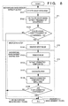
- Fig. 6 is a diagram showing the detailed procedure of the image-segment extraction step 2.
- an image segmentation step 20 through which an intermediate image segment (inclusive of the input image) contained in an image is further segmented into a background image segment and an intermediate image segment, is repeated recursively until completion of the image segmentation step 20 has been determined by an unsegmented image-segment search step 21.
- the result is extraction of image segments.
- the unsegmented image-segment search step 21 searches for image-segment data stored in the image-segment data memory 1007 and searches for intermediate image segments for which segmentation is incomplete, namely intermediate image segments not having any child nodes. In a case where the image-segment data has an intermediate image segment for which segmentation is incomplete, the image segmentation step 20 is performed using this intermediate image segment as an input intermediate image segment. In a case where the image-segment data does not have an intermediate image segment for which segmentation is incomplete, the image-segment extraction step 2 is terminated.
- the image segmentation step 20 inputs an intermediate image segment (inclusive of the input image) and judges whether the inputted-intermediate image segment can be further segmented into a background image segment and several intermediate image segments. If it is judged that further segmentation is impossible, the inputted intermediate image segment is determined to be a final image segment and this information is registered in the image-segment data of this image segment stored in the image-segment data memory 1007. If it is judged that further segmentation is possible, then the inputted intermediate image segment is segmented into a background image segment and several intermediate image segments and this information is registered in the image-segment data of this image segment stored in the image-segment data memory 1007.
- the image segment 5003 shown in Fig. 1 is an input intermediate image segment and it is judged that an intermediate image segment cannot be segmented from the image segment 5003, the image segment 5003 is determined to be a final image segment. Further, if the image segment 5004 shown in Fig. 1 is an input intermediate image segment and it is judged that an intermediate image segment can be segmented from the image segment 5004, the background image segment 5005 and the intermediate image segment 5006 are segmented from the image segment 5004.
- a background image segmentation step 22 determines whether the inputted intermediate image segment has a background image segment. If the background image segment is judged to be present, the background image segment is segmented. According to an intermediate image segmentation step 23, an image segment other than the image segment segmented as the background image segment at the background image segmentation step 22 is segmented into several intermediate image segments using a geometrical relationship. More specifically, connected pixels or connected pixels which are nearly geometrical are adopted as being one intermediate image segment. According to an image-segment registration step 24, image segments segmented at the background image segmentation step 22 and intermediate image segmentation step 23 are registered in the image-segment data memory 1007. The details of the background image segmentation step 22, intermediate image segmentation step 23 and image-segment registration step 24 will be described below.
- Fig. 7 is a diagram showing the detailed procedure of the background image segmentation step 22.
- a background color extraction step 211 analyzes the colors of the inputted intermediate image segment and judges whether the inputted intermediate image segment contains a color indicative of a background image segment. More specifically, the judgment is performed on the basis of whether pixels having a color in a specific range occupy the major part of the inputted intermediate image segment.
- a binarization step 212 creates a binary image indicative of the background image segment using the color indicating the background image segment extracted at the background color extraction step 211.
- a background image-segment shaping step 213 removes noise and small image segments from the binary image representing the background image segment created at the binarization step 212, shapes the background image segment and verifies, by the processing for removing small areas, whether the background image segment will vanish.
- Fig. 8 is a flowchart illustrating a procedure for implementing the background image segmentation step 22 by the processing executed by the CPU 2001.
- Steps S101 from S103 correspond to the background color extraction step 211.
- a color histogram is created in the working memory (RAM 2006 or storage device 2002) at step S101.
- the color histogram is three-dimensional data of RGB representing the frequency of occurrence of the color of each pixel in the intermediate image segment, namely the ratio of the number of pixels having a certain RGB value to the number of pixels of the intermediate image segment.
- quantization may be performed again when the color histogram is created. For example, in a case where an image of eight bits per R, G, B has been inputted, creating a color histogram while re-quantizing to four bits or seven bits results in a more complicated process.
- the memory size for storing the histogram can be reduced. An additional effect is that even if the color of the background image segment is uneven, a background image segment can be segmented in stable fashion.
- the colorimetric system of the image to be processed need not be an RGB colorimetric system.
- a color histogram ix created by transforming the input image to another colorimetric system in advance, e.g., an L*a*b* colorimetric system, an L*u*v* colorimetric system or an HSI colorimetric system.
- the dimensions of the color histogram also use the dimensions of the three components of the converted colorimetric system.
- the L*a*b* colorimetric system the three-dimensional data of L*a*b* is used.
- step S103 it is determined whether the maximum frequency obtained is greater than a threshold value th. If the maximum frequency is less than the threshold value th, then it is decided that the inputted intermediate image segment does not contain a background image segment and the background image segmentation step 22 is terminated. If the maximum frequency is greater than the threshold value th, then it is decided that the inputted intermediate image segment contains a background image segment and the program proceeds to step S104.
- the threshold value th which is decided upon taking the properties of the input image into account, is 0.5 (50%), by way of example.
- Step S104 which corresponds to the binarization step 212, creates, in the working memory, a binary image of the intermediate image segment binarized to the pixel having the color of maximum frequency and the pixels other than this pixel.
- the binary image created is one in which the pixel having the color of maximum frequency is made "1" and the other pixels are made "0"s.
- Steps S105 through S109 correspond to the background image-segment shaping step 213.
- noise in the created binary image is removed at step S105 by applying well-known reduction/enlargement processing, and small areas are removed from the noise-free binary image at steps S106 through S108.
- a label image is created in the working memory and connected components are extracted by well-known labeling processing at step S106.
- the label image is one in which a unique number is assigned to each connected component and the numbers are made the pixel values of the connected components.
- the number of pixels (the area) of each connected component is obtained and stored in the working memory at step S107.
- step S108 connected components for which the numbers of pixels is less than the threshold value (namely connected components of small area) are eliminated. In other words, the values of pixels corresponding to these connected components of the binary image are made "0"s.
- step S109 it is determined at step S109 whether there are any remaining connected components (background image segments). If the answer is "YES", then it is determined that there is a background image segment; otherwise, it is determined that there are no background image segments. In a case where there is a background image segment, a binary image indicative of a background image segment remains in the working memory.
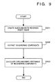
- Fig. 9 is a flowchart illustrating a procedure for implementing the intermediate image segmentation step 23 by processing executed by the CPU 2001.
- Step S201 creates an image segment other than a background image segment obtained by reversing the blacks and whites of the binary image segment indicating the background image segment created at the background image segmentation step 22, namely by changing "1" pixels to "0" pixels and changing "0" pixels to "1" pixels.
- a binary image indicating an intermediate image segment in the inputted intermediate image segment is created. This binary image is stored in a working memory.
- the binary image that has undergone the black-white reversal is segmented into intermediate image segments and neighboring components are extracted.
- “Neighboring components” are a set of closely adjacent (connection is not required) black pixels adopted as one component in a binary image. These neighboring components are adopted as an intermediate image segment.
- neighboring components refers to a column comprising a collection of characters that are not connected but closely adjacent.
- a method of extracting neighboring components is that reported by Ito et al. (see “Parallel Field Segmentation of Free-Format Documents", 1979 Information Processing Society of Japan, 20th All-Japan Convention, 2E-1).
- an image segment other than a background image segment can be segmented into one or a plurality of intermediate image segments from the inputted intermediate image segment and the position (circumscribed rectangle) thereof can be stored in the working memory.
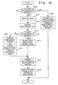
- Fig. 10 is a flowchart illustrating a procedure for implementing the image-segment registration step 24 by processing executed by the CPU 2001.
- the segmented background image segment and the intermediate image segment are registered in the form illustrated in Figs. 5A and 5B. If it has been determined that a background image segment is not present, the inputted intermediate image segment is registered as a general image segment.
- step S200 it is determined at step S200 whether a background image segment is present.- If the background image segment is not present, the program proceeds to step S219, at which the image-segment type of the node indicating the inputted intermediate image segment is changed to "general image segment" and the processing is terminated.
- a background image segment is found at step S200, a new node indicating an image segment is created at step S211, the image-segment type is registered for the new mode at step S212 and the type of image segment to be processed is discriminated at step S213. If the type of image segment is a background image segment, a binary image indicating the background image segment is registered for the shape of the image segment of the new node at step S214. If the type of image segment discriminated at step S213 is an intermediate image segment, position information obtained from the circumscribed rectangle is registered for the image-segment position of the new node at step S215. Next, step S216 registers a black-white reversed binary image, which indicates the intermediate image segment, for the shape of the image segment of the new node. It should be noted that the image-segment position of the background image segment is the same as the image-segment position of the parent node (the input intermediate image segment). Hence, the registration of this position is eliminated.
- the inputted intermediate image segment is registered as the parent node of the new node at step S217 and the new node is registered as a child node of the node indicating this input intermediate image segment at step S218. Processing is then terminated.
- the image-segment discrimination step 3 discriminates the type of each image segment extracted at the image-segment extraction step 2 and stores the result of discrimination in the image-segment data.
- An example will now be described in which it is determined whether each image segment is a "continuous color tone", a "limited-color character or line drawing", a “limited-color pseudo-halftone", a “continuous monochromatic tone”, a "limited-value character or line drawing” or a "limited-value pseudo-halftone".
- Fig. 11 is a diagram illustrating the detailed procedure of the image-segment discrimination step 3.
- a color/monochromatic discrimination step 32 it is determined by a color/monochromatic discrimination step 32 whether an image segment of interest is color or monochromatic (grayscale or black and white), then it is determined whether a color image segment is a continuous color tone or a limited color at a continuous color tone/limited-color discrimination step 33, and it is determined whether a monochromatic image segment is a continuous color tone or a limited value by a continuous monochromatic tone/limited-value discrimination step 34.
- an image segment discriminated as being a limited color or limited value it is determined whether the image segment is the image segment of a character or line drawing or the image segment of a pseudo-halftone by a character or line-drawing/pseudo-halftone discrimination step 35. Under the control of an image-segment discrimination control step 31, the foregoing steps are repeated until there are no longer any undiscriminated image segments. As a result, image-segment components of each image segment are discriminated.
- Fig. 12 is a diagram showing examples of distributions of RGB values in four image-segment components.
- Fig. 12 illustrates examples of RGB value distributions of the following image segments shown clockwise from the upper left: a "continuous color tone” image segment, a “continuous monochromatic tone” image segment, a “limited-color” image segment, and a “limited-value” image segment.
- Fig. 13 is a flowchart illustrating a procedure for implementing the color/monochromatic discrimination step 32 by processing executed by the CPU 2001.
- saturation is calculated from the pixel values (e.g., RGB values) in the image segment, a saturation histogram is created and the histogram is stored in the working memory.
- this is expressed in a colorimetric system which already includes a saturation component (S in case of HSI)
- S in case of HSI a saturation component
- the saturation histogram can be created directly using the saturation component.
- the saturation at which the frequency of the saturation histogram peaks is detected at step S302
- the variance of the saturation histogram is calculated at step S302 and image segment discrimination is performed at step S304 using the saturation and variance obtained.
- This discrimination involves judging that the image segment is a monochromatic image segment if there is a single saturation, which is located in the vicinity of zero (i.e., which is below a predetermined threshold value), at which the frequency peaks and, moreover, the variance is less than a predetermined threshold value.
- the image segment is judged to be a color image segment in all other cases.
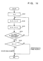
- Fig. 14 is a flowchart illustrating another example of a procedure for implementing the color/monochromatic discrimination step by processing executed by the CPU 2001. Though the precision of discrimination is inferior in comparison with the procedure of Fig. 13, discrimination can be performed in simpler fashion.
- a variable E is reset to zero at step S401, the absolute value (
- the processing of steps S402 and S403 is repeatedly executed for all pixels of the image segment. This is judged at step S404. If the processing of all of these pixels is finished, a value (E/N) which is the result of dividing the variable E by the number N of pixels in the image segment of interest is compared with a predetermined threshold value th at step S405.
- the image segment is judged to be a color image segment if E/N > th holds and to be a monochromatic image segment in all other cases.
- whether the image segment is judged to be a color image segment or a monochromatic image segment depends upon the average value of the sum of the absolute values of R-G and R-B of all pixels of the image segment.
- the continuous color tone/limited-color discrimination step 33 makes use of the fact that, in a case where the image segment is a limited-color image segment, the pixel values of the area concentrate in specific values. Based upon this fact, an image segment wherein there is a single color at which the frequency in the color histogram of the image segment indicates a peak and, moreover, there is little variance in the color histogram, is judged to be a limited-color image segment.
- Fig. 15 is a flowchart illustrating a procedure for implementing the continuous color tone/limited-color discrimination step 33 by processing executed by the CPU 2001.
- a color histogram is created from the pixel values (e.g., the RGB values) of the image segment and the histogram is stored in the working memory.
- the number frequency peaks of the color histogram is detected at step S502. Though the number of colors for which the frequency is greater than a predetermined threshold value is adopted as the number of peaks, neighboring peaks in the histogram are counted as one peak.
- the variance of the color histogram is calculated at step S503, and the image-segment component is discriminated at step S504 from the obtained number of peaks and variance.
- This discrimination involves judging that the image segment is a limited-color image segment if the number of peaks is one and, moreover, the variance is less than a predetermined threshold value.
- the image segment is judged to be an image segment of a continuous color tone in all other cases.
- the continuous monochromatic tone/limited-value discrimination step 34 makes use of the fact that, in a case where the image segment is a limited-value image segment, the pixel values of the area concentrate in specific values. Based upon this fact, an image segment wherein there is a single lightness at which the frequency in the lightness histogram of the image segment indicates a peak and, moreover, there is little variance in the lightness histogram, is judged to be a limited-value image segment.
- Fig. 16 is a flowchart illustrating a procedure for implementing the continuous monochromatic tone/limited-value discrimination step 34 by processing executed by the CPU 2001.
- step S601 lightness is calculated from the pixel values (e.g., RGB values) in the image segment, a lightness histogram is created and the histogram is stored in the working memory. In a case where this is expressed in a colorimetric system which already includes lightness, as in the case of an HSI colorimetric system, the lightness histogram can be created directly.
- the number frequency peaks of the lightness histogram is detected at step S602. Though the number of lightnesses for which the frequency is greater than a predetermined threshold value is adopted as the number of peaks, neighboring peaks in the histogram are counted as one peak.
- the variance of the lightness histogram is calculated at step S603, and the image-segment component is discriminated at step S604 from the obtained number of peaks and variance.
- This discrimination involves judging that the image segment is a limited-value image segment if the number of peaks is one and, moreover, the variance is less than a predetermined threshold value.
- the image segment is judged to be an image segment of a continuous monochromatic tone in all other cases.
- a binary image indicating the shape of an input image segment is crated at the intermediate image segmentation step 3 and the binary image is stored as image-segment data of the form illustrated in Figs. 5A and 5B.
- the image-segment shape (binary image) of an image segment to be discriminated is inputted and it is determined whether this is the image segment of a character or line drawing or the image segment of a pseudo-halftone.
- Fig. 17 is a block diagram showing the construction of an image segmentation unit 3000 for implementing the discrimination processing described above. Though the image segmentation unit in Fig. 17 is implemented by its own hardware, it goes without saying that it can be implemented also by software and the CPU 2001 of the apparatus shown in Fig. 4.
- numeral 3010 denotes a data holding unit for sequentially updating and holding each pixel value in a small area necessary for image-segment discrimination processing.
- the data holding unit 3010 receives digital binary image data 3040 that is inputted in a raster scanning format.
- the data holding unit 3010 holds data of a total of 64 pixels in an area 324 of a maximum of 8 x 8 pixels neighboring a pixel of interest 321.
- the data held is updated to data of the corresponding area in sync with the updating (sequential movement by raster scanning) of the position of the pixel of interest 321.
- Fig. 19 is a block diagram showing the construction of the data holding unit 3010.
- Numeral 3011 denotes a line buffer, which is constituted by a FIFO memories or the like, for holding data equivalent to seven lines immediately preceding the line currently being inputted.
- Numeral 3012 denotes a latch group for holding eight pixels of data per line, for a total of 64 items of data.
- numeral 3020 denotes an image-segment discriminator for discriminating whether the pixel of interest 321 is a pixel in a pseudo-halftone area based upon data of a pixel group which includes the pixel of interest 321 forming the small area 324 outputted by the data holding unit 3010.
- the image-segment discriminator 3020 includes an isolated-pixel discriminator 3021, a periodicity discriminator 3022 and a high-frequency component discriminator 3023. These three discriminators judge whether conditions that differ from one another are satisfied. If any one of the conditions is satisfied, an OR gate 3024 outputs a signal 3050 indicating that the pixel of interest 321 is a pixel in a pseudo-halftone area.
- the OR gate 3024 outputs the signal 3050, which is indicative of the pseudo-halftone area, if the pixel of interest 321 is an isolated point or a pixel contained in an isolated-pixel area, a periodic-pixel area or a high-frequency component area.
- the isolated-pixel discriminator 3021 determines whether the pixel of interest 321 resides in an isolated-pixel area. More specifically, with regard to each of 16 pixels in a 4 ⁇ 4 pixel area 322 shown in Fig. 20, it is determined by detection whether four pixels (Fig. 21), namely the pixels above, below and to the left and right, are all pixels of identical value (all white pixels or all black pixels) and whether the values of these four pixels differ from the value of the center pixel (k, l). If the results of detecting the 16 pixels are obtained and two or more of these pixels satisfy the above-mentioned condition, then it is decided that the pixel of interest 321 in the 4 ⁇ 4 pixel area 322 resides in an isolated-pixel area.
- isolated pixels black pixels or white pixels not connected at the top, bottom, left or right
- the pixel of interest 321 is judged to reside in an isolated-pixel area.
- the periodicity discriminator 3022 determines whether a pixel value is repeated at a predetermined pixel period. More specifically, with the exception of a case in which the 64 pixels in the 8 ⁇ 8 pixel area 324 in Fig. 18 are all white pixels or all black pixels, it is determined whether pixel values of four pixels segmented from each other by four pixels in the main-scan direction and/or by four pixels in the sub-scan direction, e.g., the pixel values of pixels A, B, C, D indicated by the hatching in Fig. 18, are all the same or not. It should be noted that, in the 8 ⁇ 8 pixel area 324, it is possible to define 16 sets of four pixels in the relative positional relationship of the kind indicated by the pixels A, B, C, D.
- each of these 16 sets it is determined whether the pixel values of the four pixels are all equal or not. If they are, say, 14 sets in which the four pixels are all equal, it is determine that the portion is a periodic portion, namely a dither portion, with the exception of a case where all 64 pixels are white pixels or black pixels.
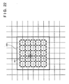
- the high-frequency component discriminator 3023 determines whether a change is density occurs frequently between adjacent pixels. More specifically, in a 6 ⁇ 6 pixel area shown in Fig. 22, the discriminator 3023 determines whether there is a difference between the pixel values of two mutually adjacent pixels in 60 sets thereof obtained by combining 30 combinations (indicated by the horizontal bidirectional angles in Fig. 22) between two mutually adjacent pixels of 36 pixels in the horizontal (main-scan) direction and 30 combinations (indicated by the vertical bidirectional angles in Fig. 22) between two mutually adjacent pixels of 36 pixels in the vertical (sub-scan) direction. Further, if there are, say, 28 or more sets of mutually different combinations, the discriminator 3023 judges that a pixel resides in a high-frequency component area.
- the results of discrimination (the image-segment components of each image segment) at the image-segment discrimination step 3 are stored, as image-segment components of each image segment, in the image-segment data in the image-segment data memory 1007.
- image-segment components of each image segment in the image-segment data in the image-segment data memory 1007.
- the mean color in the image segment e.g., the average pixel value of each of the colors RGB
- the adaptive zooming step 4 subjects each image segment extracted at the image-segment extraction step 2 to zoom processing conforming to the image-segment component discriminated at the image-segment discrimination step 3, thereby creating a zoomed image of the input image.
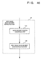
- Fig. 23 is a diagram illustrating the detailed procedure of the adaptive zooming step 4.
- the adaptive zooming step 4 adapts the zooming step, which conforms to the image-segment component, for every image segment and then combines the zoomed images of the respective image segments, thereby creating a zoomed image of the input image. This is performed under the control of a zoom control step 41.
- the image segment of a continuous color tone is zoomed at a continuous color-tone image-segment zooming step 42
- the image segment of a limited-color character or line drawing is zoomed at a limited-color character/line-drawing image-segment zooming step 43
- the image segment of a limited-color pseudo-halftone is zoomed at limited-color pseudo-halftone image-segment zooming step 44
- the image segment of a continuous monochromatic tone is zoomed at a continuous monochromatic-tone image-segment zooming step 45
- the image segment of a limited-value character or line drawing is zoomed at a limited-value character/line-drawing image-segment zooming step 46
- the image segment of a limited-value pseudo-halftone is zoomed by a limited-value pseudo-halftone image-segment zooming step 47
- the resulting zoomed image segments are combined into a single zoomed image.
- the zoom control step 41 adaptively applies the zoom process conforming to an image-segment component to each and every image segment until there are no longer any image segments for which zooming has not been completed.
- Fig. 24 is a diagram illustrating a sequence of image segments which undergo zooming. Zooming is performed while pursuing image-segment nodes, which are described in image-segment data (having the tree structure), from route nodes (the most significant nodes). However, the zooming of each image segment must not be carried out ahead of a background image segment which is one rank below a node superior to the image segment itself. In other words, in a case where an image segment inferior to one intermediate image segment is zoomed, zooming must be performed from the background image segment.
- the continuous color-tone image-segment zooming step 42 zooms an inputted image segment as by a color image zooming method using linear interpolation and writes the data of the zoomed image in the zoomed-image memory 1008. Though the writing of the zoomed-image data in the zoomed-image memory 1008 is the same as in other steps, this performed based upon the position of the zoomed image segment calculated from the image-segment position of the inputted image segment.
- the binary image stored as the image-segment shape data of the inputted image segment is zoomed by a well-known binary-image zooming method suited to a character or line-drawing image, such as the method in Japanese Patent Application No. 3-345062 already filed by the applicant, and the data of this zoomed image is written in the zoomed-image memory 1008.
- the binary image stored as the image-segment shape data of the inputted image segment is zoomed by a binary-image zooming method such as the SPC zooming method and the data of this zoomed image is written in the zoomed-image memory 1008.
- the writing of the zoomed image data is performed by writing the pixel value of the input image in a case where pixel value of the zoomed binary image is "1" and not writing a pixel for which the pixel value is "0".
- a value written need not be a pixel value in the input image but may be an image-segment color of the inputted image segment. If such is the case, noise contained in the input image can be removed.
- an inputted image segment is zoomed as by a color-image zooming method using linear interpolation and the data of the zoomed image is written in the zoomed-image memory 1008.
- the binary image stored as the image-segment shape data of the inputted image segment is zoomed by the well-known binary-image zooming method suited to a character or line-drawing image, such as the method in Japanese Patent Application No. 3-345062 already filed by the applicant, and the data of this zoomed image is written in the zoomed-image memory 1008.
- the binary image stored as the image-segment shape data of the inputted image segment is zoomed by a binary-image zooming method such as the SPC zooming method and the data of this zoomed image is written in the zoomed-image memory 1008.
- the writing of the zoomed image data is performed by writing the pixel value of the input image in a case where pixel value of the binary image, which is obtained by SPC zooming of the binary image stored as the image-segment shape data of the inputted image segment, is "1" and not writing a pixel for which the pixel value is "0".
- a value written need not be a pixel value in the input image but may be an area color of the inputted image segment or the color black (e.g., in a case where the output image consists of eight bits per each of the colors R, G, B, all pixel values of RGB are zero). If such is the case, noise contained in the input image can be removed.
- the zoom ratio employs a value stored in the ROM 2004 in advance or a value designated by the user from a keyboard or DIP switch.
- a document image inputted as a color image and consisting of a mixture of image segments having different components is subjected to image segmentation based upon the features of the color document image, whereby it is possible to segment image segments from the document image in excellent fashion even if the document image is one having a plurality of backgrounds whose colors are other than white.
- a segmented image segment is subjected to zoom processing that conforms to the characteristics of this area, as a result of which a zoomed color image having excellent image quality can be obtained.
- Fig. 25 is a diagram showing a processing procedure for a case in which the present invention is applied to processing for compressing a color image in an image processing apparatus. Steps from the color image input step 1 to the image-segment discrimination step 3 and the color image output step 5 are the same as in the first embodiment and a detailed description thereof is omitted.
- an adaptive compression step 6 creates compressed data indicative of input image data by applying each image segment extracted at the image-segment extraction step 2 to compression processing that conforms to the image-segment component of the image segment discriminated by the image-segment discrimination step 3.
- a compressed-data output step 7 the compressed data created at the adaptive compression step 6 is outputted to a communication line or image storage device, which are not shown.
- the data compressed at the adaptive compression step 6 inputs from a communication line or image storage device at a compressed-data input step 8.
- the data compressed at the adaptive compression step 6 is reproduced as a color image at a color image reproduction step 9. It should be noted that the steps from the color image input step 1 to the compressed-data output step 7 are executed when the color image data is compressed.
- the steps from the compressed-data input step 8 to the color image output step 5 are executed when the compressed data is reproduced.
- Fig. 26 is a block diagram showing the construction of an image processing apparatus which executes the processing shown in Fig. 25, and Fig. 27 is a block diagram showing hardware for implementing the arrangement of Fig. 26.
- this embodiment is further provided with a data input unit 2010 and a data output unit 2011, both of which are connected to the I/O port 2005.
- the color image input unit 1001 inputs digital color image data to be processed and stores this data in the input image memory 1006.
- the image-segment extraction unit 1002 extracts image segments from the image that has been stored in an input image memory 1006 and stores the extracted image-segment data in an image-segment data memory 1007.
- the image-segment discrimination unit 1003 discriminates image-segment components in each image segment extracted by the image-segment extraction unit 1002 and stores the image-segment components in the image-segment data memory 1007.
- An adaptive compression unit 1014 creates compressed data indicative of input image data by applying each image segment extracted by the image-segment extraction unit 1002 to compression processing that conforms to the image-segment component of the image segment discriminated by the image-segment discrimination unit 1003.
- the compressed data is stored in a compressed-data memory 1012.
- a compressed-data output unit 1009 outputs compressed data compressed by the adaptive compression unit 1014 and stored in the compressed-data memory 1012.
- the destination of this output is a communication line or an image storage device.
- An arrangement can be adopted in which, under the control of the CPU 2001 which operates in accordance with a program stored in the ROM 2004 or storage device 2002, the data output unit 2011 outputs the compressed data that has been stored in the RAM 2006 or storage device 2002.
- the compressed-data input unit 1011 inputs the compressed data from the communication line or image storage device and stores the compressed data in the compressed-data memory 1012.
- An arrangement can be adopted in which, under the control of the CPU 2001 which operates in accordance with the program stored in the ROM 2004 or storage device 2002, compressed data sent via the communication line or compressed data stored in the image storage device is inputted by the data input unit 2010.
- a color image reproduction unit 1010 reproduces color image data from the compressed data that has been stored in the compressed-data memory 1012 and stores the color image data in a reproduced-image memory 1013.
- the reproduced color image data stored in the reproduced-image memory 1013 is outputted by the color image output unit 1005.
- the destination of this output is a display, a printer or copier for making hard copies, a communication line or an image storage device.
- the adaptive compression unit 1014 and color image reproduction unit 1010 can be realized by the CPU 2001, which operates in accordance with the program stored in the ROM 2006 or storage device 2002, and the RAM 2006 or memory device 2002 used as a working memory. It goes without saying that these can also be realized by their own CPUs, RAMs and memories or by their own hardware. Further, the compressed-data memory 1012 and the reproduced-image memory 1013 can be realized by the RAM 2006 or memory device 2002. It goes without saying that these memories can be realized by their own storage devices.
- Fig. 29 is a diagram showing the structure of the compressed data.
- the compressed data is composed of a header (referred to as a "compressed-data header” below), in which are registered the image size and the compression method for the type of image-segment component, and the compressed data (referred to as “compressed image-segment data” below) of each image segment.
- the compressed image-segment data contains the image-segment data of the image segment.
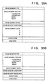
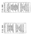
- Figs. 30A and 30B are diagrams showing the form of image-segment data contained in compressed image-segment data.
- Image-segment data whose form is either of two types is held in dependence upon the image-segment component. More specifically, in case of a "limited-color character or line-drawing image segment", a “limited-color pseudo-halftone image segment”, a “limited-value character or line-drawing image segment” or a "limited-value pseudo-halftone image segment", image-segment data of the form shown in Fig. 30A is held.
- Each element shown in Fig. 30A corresponds to a respective ones of the elements shown in Fig. 5B.
- a binary image indicative of the shape of an image segment is registered as "image-segment shape”.
- a binary image compressed by a compression method stored in the compressed-data header is registered as "image-segment shape”.
- image-segment data of the form shown in Fig. 30B is held. It should be noted that elements other than “image-segment shape" and “image-segment image data" correspond to respective ones of the elements shown in Fig. 5B, data compressed by a compression method registered in the compressed-data header is registered as “image-segment image data” and a binary image compressed by a method of compressing a limited-value character or line-drawing image segment is registered as "image-segment shape".
- the adaptive compression step 6 creates compressed data indicative of input image data by applying each image segment extracted at the image-segment extraction step 2 to compression processing that conforms to the image-segment component discriminated by the image-segment discrimination step 3.
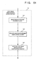
- Fig. 31 is a diagram showing the detailed procedure of the adaptive compression step 6.
- the adaptive compression step 6 adapts the compression step, which conforms to the particular image-segment component, for every image segment, thereby creating compressed data for each image segment, and stores the compressed data in the compressed-data memory 1012.
- the image segment of a continuous color tone is compressed at a continuous color-tone image-segment compression step 62
- the image segment of a limited-color character or line drawing is compressed at a limited-color character/line drawing image-segment compression step 63
- the image segment of a limited-color pseudo-halftone is compressed at a limited-color pseudo-halftone image-segment compression step 64
- the image segment of a continuous monochromatic tone is compressed at a continuous monochromatic-tone image-segment compression step 65
- the image segment of a limited-value character or line drawing is compressed at a limited-value character/line-drawing image-segment compression step 66
- the image segment of a limited-value pseudo-halftone is compressed by a limited-value pseudo-halftone image-segment compression step 67.
- the compression control step 61 adaptively applies the compression process conforming to an image-segment component to each and every image segment until there are no longer any image segments that have not been compressed.
- the continuous color-tone image-segment compression step 62 compresses a continuous color-tone image segment and stores the created compression data in the compressed-data memory 1012. More specifically, an image portion corresponding to the image-segment position of node to be processed is compressed by a coding method suited to a continuous color tone and the compressed data is registered as the "image-segment image data" shown in Fig. 30B. Further, the "image-segment shape" in the image-segment data stored in the image-segment data memory 1007 is compressed by the compression method of a limited-value character or line-drawing image segment, the compressed data is registered in the "image-segment shape" shown in Fig. 30B, and values the same as the image-segment data are registered as the other elements. It should be noted that JPEG coding using DCT, for example, is utilized as the coding method suited to the continuous color tone.
- the limited-color character/line drawing image-segment compression step 63 compresses a limited-color character or line-drawing image segment and stores the created compressed data in the compressed-data memory 1012. More specifically, a binary image stored as the image-segment shape of node to be processed is compressed by coding suited to a limited-color character or line drawing, the compressed data is registered as "image-segment shape" shown in Fig. 30A, and values the same as the image-segment data are registered as the other elements. It should be noted that MR/MMR coding, for example, is utilized as the coding method suited to the limited-color character or line drawing.
- the limited-color pseudo-halftone image-segment compression step 64 compresses a limited-color pseudo-halftone image segment and stores the created compressed data in the compressed-data memory 1012. More specifically, a binary image stored as the image-segment shape of node to be processed is compressed by coding suited to a limited-color pseudo-halftone, the compressed data is registered as "image-segment shape" shown in Fig. 30A, and values the same as the image-segment data are registered as the other elements. It should be noted that JBIG coding, for example, is utilized as the coding method suited to the limited-color pseudo-halftone.
- the continuous monochromatic-tone image-segment compression step 65 compresses a continuous monochromatic-tone image segment and stores the created compressed data in the compressed-data memory 1012. More specifically, an image portion corresponding to the image-segment position of a node to be processed is compressed by coding suited to a continuous monochromatic tone and the compressed data is registered as "image-segment image data" shown in Fig. 30B. Further, "image-segment shape" in the image-segment data stored in the image-segment data memory 1007 is compressed by a compression method for a limited-value character or line-drawing image segment and the compressed data is registered as "image-segment shape" shown in Fig. 30B, and values the same as the image-segment data are registered as the other elements. It should be noted that JPEG coding, for example, is utilized as the coding method suited to the continuous monochromatic tone.
- the limited-value character/line drawing image-segment compression step 66 compresses a limited-value character or line-drawing image segment and stores the created compressed data in the compressed-data memory 1012. More specifically, a binary image stored as the image-segment shape of node to be processed is compressed by coding suited to a limited-value character or line drawing, the compressed data is registered as "image-segment shape" shown in Fig. 30A, and values the same as the image-segment data are registered as the other elements. It should be noted that MR/MMR coding, for example, is utilized as the coding method suited to the limited-value character or line drawing.
- the limited-value pseudo-halftone image-segment compression step 67 compresses a limited-value pseudo-halftone image segment and stores the created compressed data in the compressed-data memory 1012. More specifically, a binary image stored as the image-segment shape of node to be processed is compressed by coding suited to a limited-value pseudo-halftone, the compressed data is registered as "image-segment shape" shown in Fig. 30A, and values the same as the image-segment data are registered as the other elements. It should be noted that JBIG coding, for example, is utilized as the coding method suited to the limited-value pseudo-halftone.
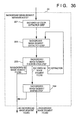
- the color image reproduction step 9 reproduces color image data from compressed data that has been stored in the compressed-data memory 1012.
- Fig. 32 is a diagram showing the detailed procedure of the color image reproduction step 9.
- the color image reproduction step 9 reproduces a color image by applying, for each image segment, a reproduction process conforming to the "image-segment type" of the image-segment data contained in the compressed image-segment data, and stores this color image is stored the reproduced-image memory 1013.
- reproduction is performed at a continuous color-tone image-segment reproduction step 92 in case of a continuous color tone, at a limited-color character/line drawing image-segment reproduction step 93 in case of a limited-color character or line drawing; at a limited-color pseudo-halftone image-segment reproduction step 94 in case of a limited-color pseudo-halftone; at a continuous monochromatic-tone image-segment reproduction step 95 in case of a continuous monochromatic tone; at a limited-value character/line-drawing image-segment reproduction step 96 in case of a limited-value character or line drawing; and at a limited-value pseudo-halftone image-segment reproduction step 97 in case of a limited-value pseudo-halftone.
- the reproduced image segments are combined into a single reproduced image.
- the reproduction control step 91 adaptively applies the reproduction process conforming to the image-segment type to each and every image segment until there is no longer any compressed image-segment data that has not been reproduced.
- the reproduction of image segments is performed in the sequence shown in Fig. 24.
- image-segment reproduction is performed while pursuing image-segment nodes, which are described in image-segment data (having the tree structure), from route nodes (the most significant nodes).
- the reproduction of each image segment must not be carried out ahead of a background image segment which is one rank below a node superior to the image segment itself. In other words, in a case where an image segment inferior to one intermediate image segment is reproduced, reproduction must be performed from the background image segment.
- the continuous color-tone image-segment reproduction step 92 reproduces an image segment from compressed image-segment data of a continuous color tone and stores this image segment in the reproduced-image memory 1013.
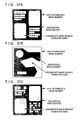
- Fig. 33 is a flowchart illustrating the detailed procedure of the continuous color-tone image-segment reproduction step 92. This flowchart is executed by the CPU 2001, by way of example.
- step S701 data registered as "image-segment shape" of the compressed image-segment data is decoded by a decoding method corresponding to the method of coding of the limited-value character or line-drawing image segment registered in the compressed-data header. As a result, binary image data indicating the image-segment shape is reproduced and stored in the working memory.
- step S702 data registered as "image-segment image data" of the compressed image-segment data is decoded by a decoding method corresponding to the method of coding of the continuous color-tone image segment registered in the compressed-data header. As a result, image-segment image data is reproduced and stored in the working memory.
- pixels of the reproduced image-segment image data which correspond to pixels of value "1" in the reproduced binary-image data are stored in the reproduced-image memory 1013. It should be noted that the writing of reproduced image data in the reproduced-image memory 1013 is the same as in the other steps and is performed based upon position calculated from "image-segment position" of the compressed image-segment data.
- the limited-color character/line drawing image-segment reproduction step 93 reproduces an image segment from compressed image-segment data of a limited-color character or line drawing and stores the image segment in the reproduced-image memory 1013.
- Fig. 34 is a flowchart illustrating the detailed procedure of the limited-color character/line drawing image-segment reproduction step 93. This flowchart is executed by the CPU 2001, by way of example.
- step S801 data registered as "image-segment shape" of the compressed image-segment data is decoded by a decoding method corresponding to the method of coding of the limited-color character or line-drawing image segment registered in the compressed-data header. As a result, binary image data indicating the image-segment shape is reproduced and stored in the working memory.
- step S802 pixels registered as the "image-segment color" of the compressed image-segment data are stored at positions in the reproduced-image memory 1013 which correspond to pixels of value "1" in the reproduced binary-image data.
- the limited-color pseudo-halftone image-segment reproduction step 94 reproduces an image segment from compressed image-segment data of a limited-color pseudo-halftone and stores the image segment in the reproduced-image memory 1013.
- the limited-color pseudo-halftone image-segment reproduction step 94 reproduces image segments through a procedure similar to that of the limited-color character/line drawing image-segment reproduction step 93 illustrated in Fig. 34.
- the continuous monochromatic-tone image-segment reproduction step 95 reproduces an image segment from compressed image-segment data of a continuous monochromatic tone and stores this image segment in the reproduced-image memory 1013.
- the continuous monochromatic-tone image-segment reproduction step 95 reproduces image segments through a procedure similar to that of the continuous color-tone image-segment reproduction step 92 shown in Fig. 33.
- the limited-value character/line drawing image-segment reproduction step 96 reproduces an image segment from compressed image-segment data of a limited-value character or line drawing and stores the image segment in the reproduced-image memory 1013.
- the limited-value pseudo-halftone image-segment reproduction step 97 reproduces an image segment from compressed image-segment data of a limited-value pseudo-halftone and stores the image segment in the reproduced-image memory 1013.
- the limited-value character/line drawing image-segment reproduction step 96 and the limited-value pseudo-halftone image-segment reproduction step 97 reproduce image segments through a procedure similar to that of the limited-color character/line drawing image-segment reproduction step 93 shown in Fig. 34.
- a document image inputted as a color image and consisting of a mixture of image segments having different components is subjected to image segmentation based upon the features of the color document image, whereby it is possible to segment image segments from the document image in excellent fashion even if the document image is one having a plurality of backgrounds whose colors are other than white.
- a segmented image segment is subjected to compression processing that conforms to the characteristics of this area, as a result of which compressed data can be obtained at an excellent compression rate.
- compressed image-segment data contained in this compressed data can be decompressed by a method conforming to the characteristics of the image segment, thereby making it possible to obtain a reproduced color image having an excellent image quality.
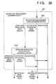
- Fig. 35 is a diagram showing a processing procedure for a case in which the present invention is applied to document image editing processing in an image processing apparatus. Steps from the color image input step 1 to the image-segment discrimination step 3 are the same as those of the first embodiment and need not be described in detail again.
- image-segment data created by the process up to the image-segment discrimination step is converted, for each image segment, to image data having a data format suitable for the editing of a document image in a DTP apparatus or the like.
- an input image can be applied to document-image editing processing per each image segment segmented by the process up to the image-segment discrimination step 3, and this editing can also be performed per each image segment.
- characters or symbols contained in a limited-color character of line-drawing image segment or limited-value character of line-drawing image segment can also be converted to character codes by character recognition in dependence upon a designation made by the user.
- data having a raster-scanning format can also be converted to vector data by raster-vector conversion in dependence upon a designation made by the user.
- a character image is edited in accordance with a designation from the user and a document image representing the results of editing is outputted.
- the foregoing processing can also be implemented in a DTP apparatus or in a special-purpose apparatus illustrated in the first embodiment.
- a document image inputted as a color image and consisting of a mixture of image segments having different components is subjected to image segmentation based upon the features of the color document image, whereby it is possible to segment image segments from the document image in excellent fashion even if the document image is one having a plurality of backgrounds whose colors are other than white.
- a color original image can be structured and inputted into a document-image editing apparatus such as a DTP apparatus.
- a segmented image segment is subjected to editing processing conforming to the characteristics of the image segment so that a color document image having excellent image quality can be obtained.
- a background image segmentation step determines whether an intermediate image segment contains a background image segment and then segments the background image segment.
- this step entails extracting, as the background image segment, an image segment of the same color occupying the major part of the intermediate image segment to be processed.
- Such method is effective in many color document images.
- a color document image containing a continuous tone image segment such as a photographic image having portions in which there is little change in brightness or color
- a background image segment is judged to reside in a continuous tone image segment that must properly be judged as being a single image segment, with the result that the continuous tone image segment is needlessly segmented into a continuous tone image segment and an intermediate image segment.
- a background image segmentation process is described in which, by judging whether an extracted background image segment is appropriate or not, it is possible to prevent the needless segmenting of a continuous tone image segment having a portion in which there is little change in brightness or color.
- Fig. 36 is a diagram showing the detailed procedure of the background image segmentation step 22 according to this embodiment. This corresponds to Fig. 7 of the first embodiment.
- a background color extraction step 221 analyzes the colors of the inputted intermediate image segment and extracts the color of the background image segment. More specifically, in the inputted intermediate image segment, a pixel having the most prevalent color or a color close to this color in comparison with the pixels of other colors has this most prevalent color extracted.
- a background image-segment extraction step 222 uses the extracted color of the background image segment to create a binary image of the background image segment.
- a background image-segment discrimination step 223 judges whether an image segment indicated by the created binary image is appropriate as a background image. If the image segment indicated is judged to be appropriate, processing proceeds to a background image-segment shaping step 224.
- the background image-segment shaping step 224 removes noise and small image segments from the binary image indicating the image segment judged as being an appropriate-background image segment, shapes the background image segment and verifies, by the processing for removing small areas, whether the background image segment will vanish.
- Figs. 37A through 37C are diagrams for describing an overview of processing for judging a background image segment.
- Fig. 37A shows an example in which a background image segment is extracted from an intermediate image segment containing a background image segment
- Fig. 37B shows an example in which a background image segment is extracted from an intermediate image segment of a continuous tone image segment such as a photograph
- Fig. 37C shows an example in which a background image segment is extracted from an intermediate image segment of a color document image having a large amount of noise.
- the background image-segment discrimination step 223 judges that the result of extraction shown in Fig. 37A is indicative of an appropriate background image segment and judges that the results of extraction shown in Figs. 37B and 37C are indicative of inappropriate background image segments.
- the background image-image segment discrimination step 223 determines the existence of a continuous tone portion having a small change in brightness or color and judges that the extracted image segment is inappropriate as a background image.
- the background image-image segment discrimination step 223 determines that a background image segment has not been extracted sufficiently and judges that the extracted image segment is inappropriate as a background image.
- Fig. 38 is a diagram illustrating the detailed procedure of the background image-segment discrimination step 223.
- a background image-segment shape discrimination step 2231 determines whether the shape of an image segment extracted as a background image segment is broad enough in the inputted intermediate image segment.
- a generated intermediate image-segment discrimination step 2232 determines whether a large number of image segments of small area reside in a newly generated intermediate image segment, as described above.
- Figs. 39 through 41 show a flowchart illustrating a procedure for implementing the background image segmentation step of this embodiment by processing executed by the CPU 2001. This corresponds to Fig. 8 of the first embodiment.
- Steps S901 and S902 correspond to the background color extraction step 221.
- a color histogram is created in the working memory at step S901, and a color having the maximum frequency of occurrence (namely a candidate for the background color) is obtained at step S902.
- Step S903 which corresponds to the background image-segment extraction step 222, creates binary image data in the working memory.
- This is binary image data of an intermediate image segment that has been binarized to pixels having a color close to the color of maximum frequency of occurrence and pixels other than these pixels.
- binary image data is created in which pixels having a color close to the color of maximum frequency of occurrence are made "1"s and pixels other than these pixels are made "0"s. Whether or not a pixel of interest has a color near the color of maximum frequency is determined by obtaining the distance D in accordance with the equation shown below.
- D 2 (R0 - R1) 2 + (G0 - G1) 2 + (B0 - B1) 2 where R0, G0, B0 are R, G, B values of maximum frequency of appearance, and R1, G1, B1 are R, G, B values of the pixel of interest.
- the value of the background range uses data stored in the ROM 2004 or the like as the initial value thereof but the value is changed in dependence upon the result of discrimination performed at the background image-segment discrimination step 223.
- step S904 to S908 correspond to the background image-segment shape discrimination step 2231.
- the area (which shall be referred to as the "background outside area") on the outer side of the image segment extracted as the background image segment is measured at step S904, and the area of the inputted intermediate image segment is measured at step S905.
- Fig. 42 is a diagram for describing a method of measuring the background outside area.
- the number of pixels (representative of area) for which flags have not been raised is measured from left and right boundaries of the intermediate image segment to the sides of the image segment extracted as the background image segment, and the flags are raised for the pixels thus measured.
- a similar measurement is performed with regard to the main scan but pixels whose flags have raised by the measurement in the sub-scan direction are not measured.
- the ratio is less than the threshold value, it is judged that the extracted image segment is appropriate as the background image segment and the program proceeds to step S909; otherwise, it is judged that the extracted image segment is inappropriate as the background image segment and the program proceeds to step S907.
- Steps S907 and S908 determine whether extraction of a background image segment is to be performed again. This determination uses a re-extraction flag A, which indicates whether this is the initial discrimination of a background image-segment shape, and the background outside area ratio prevailing immediately prior to re-extraction (this ratio shall be referred to as the "preceding extraction ratio"). It should be noted that these values are stored in the RAM 2006.
- step S903 the program proceeds to step S903 and re-extraction is executed; otherwise, the program proceeds to step S908, where the value of (background outside-area ratio)/(preceding extraction ratio) is compared with a predetermined threshold value. If the threshold value is larger, the program returns to step S903 and re-extraction is executed; otherwise, it is judged that there is no background image segment and processing is terminated. It should be noted that in the case where re-extraction is performed, the background color range is widened. If the discrimination of the background image segment of the inputted intermediate image segment is finished, the re-extraction flag A and the background color range are reset.
- Steps from step S909 to S915 correspond to the generated intermediate image-segment discrimination step 2232.
- the binary image representing background image segment undergoes a black-white reversal at step S909, connected components are extracted from the black-white reversed binary image at step S910, the area of the extracted connected components is measured at step S911, and the number of connected components for which the area is less than a predetermined threshold value (these connected components shall be referred to as "small connected components") is measured.
- the number of small connected components is compared with a predetermined threshold value at step S913. If the number is less than the threshold value, it is judged that the extracted image segment is appropriate as the background image segment and the program proceeds to step S916; otherwise, it is judged that the extracted image segment is inappropriate as the background image segment and the program proceeds to step S914.
- Whether or not extraction of background image segment is to be performed again is determined at steps S914 and S915.
- This determination uses a re-extraction flag B, which indicates whether this is the initial discrimination of a generated intermediate image-segment, and the number of small connected components prevailing immediately prior to re-extraction (this number shall be referred to as the "preceding extraction number"). It should be noted that these values are stored in the RAM 2006.
- step S914 If the re-extraction flag B is discriminated and this is found to be the initial discrimination at step S914, then the program returns to step S903 and re-extraction is executed; otherwise, the program proceeds to step S915, where the value of (number of small connected components)/(preceding extraction number) is compared with a predetermined threshold value. If the threshold value is larger, the program returns to step S903 and re-extraction is executed; otherwise, it is judged that-there is no background image segment and processing is terminated. It should be noted that in the case where re-extraction is performed, the background color range is widened. If the discrimination of the background image segment of the inputted intermediate image segment is finished, the re-extraction flag B and the background color range are reset.
- Steps S916 through S920 correspond to the background image-segment shaping step 224.
- noise is removed from the binary image, which represents the extracted background image segment, by application of well-known reduction/enlargement processing, and small image segments are removed from the noise-free binary image at steps S917 through S919.
- a label image is created in the working memory and connected components are extracted by well-known labeling processing at step S917.
- the label image is one in which a unique number is assigned to each connected component and the numbers are made the pixel values of the connected components.
- the number of pixels (the area) of each connected component is obtained and stored in the working memory at step S918.
- step S919 connected components for which the numbers of pixels are less than the threshold value (namely connected components of small area) are eliminated. In other words, the values of pixels corresponding to these connected components of the binary image are made "0"s.
- step S920 it is determined at step S920 whether there are any remaining connected components (background image segments). If the answer is "YES", then it is determined that there is a background image segment; otherwise, it is determined that there are no background image segments. In a case where there is a background image segment, a binary image indicative of a background image segment remains in the working memory.
- a background image segmentation step is proposed in which it is determined whether the extracted background image segment is appropriate or not, thus making it possible to avoid needless splitting of an image segment in a color document image having a portion in which there is little change in brightness and color, and in a color document image having a large amount of noise.
- a color document image in which image segments having different characteristic are mixed can be subjected to excellent processing (image zooming, reduction of quantity of data and structuring of data, etc.).
- Each of the foregoing embodiments makes it possible segment a color image into image segments in excellent fashion.
- segmentation into image segments requires a great detail of processing time.
- fields which utilize image segmentation methods employ DTP and filing systems are premised upon processing for carrying out dialog with the user and there is a need for high-speed processing that can be executed without hindering the processing for effecting the dialog with the user.
- the techniques of the foregoing embodiments are provided in the form of software and implemented by a computer, there are situations in which too much processing time is needed when the input image is large.
- this embodiment does not directly apply the techniques of the foregoing embodiments to the input image but applies them instead to an image obtained by reducing the input image.
- image segments are extracted at a high speed equivalent to that obtained when direct extraction is performed using the input image, with the extraction of this embodiment being based upon data indicative of image segments extracted from a reduced image.
- the color of background can be assumed in advance (to be white, for example) in the case of a binary image, but the color of background cannot be assumed in the case of a color image to which this embodiment is applied.
- image segments necessary when creating a reduced image are eliminated, as a result of which image segments happen to be omitted.
- this can be avoided by giving priority to elimination of white pixels constituting the background.
- the conventional binarization method can be directly applied to color document image.
- Fig. 43 is a diagram showing a processing procedure in an image processing apparatus according to a fifth embodiment.
- a digital color image to undergo processing is inputted at a color image input step 1
- a reduced image is created from the input color image at a reduced-image image-segment extraction step 13
- an image segment is extracted from the input image based upon image-segment data extracted from the reduced image.
- Fig. 44 is a diagram showing the construction of a color image processing apparatus which executes the processing illustrated in Fig. 43.
- the hardware for implementing the arrangement shown in Fig. 44 has a construction the same as that of Fig. 3 described in the first embodiment and need not be described again.
- the color image input unit 1001 inputs digital color image data to be processed and stores this data in the input image memory 1006.
- a reduced-image creation unit 1102 creates reduced-image data from the color image data stored in the input image memory 1006 by the color image input unit 1001 and stores the created data in the a reduced-image memory 1106.
- a reduced-image image-segment extraction unit 1103 extracts an image segment from the reduced image created by the reduced-image creation unit 1102 and stored in the reduced-image memory 1106 and stores this image-segment data in the image-segment data memory 1007.
- An input-image image-segment extraction unit 1104 extracts an image segment in the input image from the image-segment data of the reduced image extracted by the reduced-image image-segment extraction unit 1103 and stored in the image-segment data memory 1007 and stores this image-segment data in the image-segment data memory 1007.
- the reduced-image creation unit 1102, the reduced-image image-segment extraction unit 1103 and the input-image image-segment extraction unit 1104 can be realized by the CPU 2001, which operates in accordance with the program stored in the ROM 2006 or storage device 2002, and the RAM 2006 or memory device 2002 used as a working memory. It goes without saying that these can also be realized by their own CPUs, RAMs and memories or by their own hardware.
- the input image memory 1006, the reduced-image memory 1106 and the image-segment data memory 1007 can be realized by the RAM 2006 or memory device 2002 in Fig. 4. It goes without saying that these memories can be realized by their own storage devices.
- the color image input step 1 inputs digital color image data to be processed and stores the inputted image data in the input image memory 1006.
- a reduced-image creation step 12 creates reduced-image data of the color image data stored in the input image memory 1006 by the color image input step 1 and stores the created data in the a reduced-image memory 1106.
- the reduced image is obtained by reducing the size of the input image in the horizontal and vertical directions by 1/N (where N is an arbitrary natural number and 1/N shall be referred to as the "reduction ratio").
- the reduction ratio should be within a range which will not influence subsequent processing even through reduction is carried out and is designated suitably depending upon the size and content of the input image.
- the reduced-image creation step 12 can be implemented by a well-known method of Greating an image in which pixels are removed by being thinned out.
- An example of creation of an image reduced by 1/2 in the vertical and horizontal directions by a well-known method of creating an image in which pixels are removed by being thinned out is as follows: The input image is divided into blocks 3101 of two pixels vertically and two pixels horizontally (four a total of four pixels) shown in Fig. 45, and one pixel in each block (say a pixel 3102 in the upper left-hand corner) is made one corresponding pixel 3103 of the reduced image, whereby an image reduced by 1/2 vertically and horizontally can be created.
- an image reduced to 1/N vertically and horizontally can be obtained if the blocks are made three pixels in each of the horizontal and vertical directions (for a total of nine pixels), four pixels in each of the horizontal and vertical directions (for a total of 16 pixels), five pixels in each of the horizontal and vertical directions (for a total of 25 pixels), etc.
- an average value of each of the R, G, B values of all pixels in the block may be adopted as the pixel value of the reduced image.
- a reduced-image image-segment extraction step 13 extracts an image segment from the reduced image created by the reduced-image creation unit 12 and stored in the reduced-image memory 1106 and stores this extracted image-segment data in the image-segment data memory 1007.
- the reduced-image image-segment extraction step 13 can be realized by the image-segment extraction step 2 described in the first embodiment.
- An input-image image-segment extraction step 14 creates image-segment data in an input image from image-segment data of a reduced image extracted by the reduced-image image-segment extraction step 13 and stored in the image-segment data memory 1007.
- Fig. 46 Part of the input-image image-segment creation step 14 is shown in Fig. 46.
- the manner of processing of the input-image image-segment creation step 14 is illustrated in Fig. 47.
- the process illustrated in Fig. 46 is performed with regard to all image segments that have been stored in the image-segment data.
- an image-segment position conversion step 141 calculates an image-segment position (indicated at 4002 in Fig. 47) in the input image from an image-segment position (indicated at 4001 in Fig. 47) in a reduced image of image-segment data.
- the calculated position is stored in the image-segment- data. More specifically, the X, Y coordinates and values of width and height of the image-segment position are multiplied by the reciprocal N of the reduction ratio.
- An input-image image-segment shape extraction step 142 extracts an image-segment shape of the input image in a rectangular image segment of the image-segment position in the input image calculated at the image-segment position converting step 141. More specifically, a rectangular image segment of the image-segment position calculated at the image-segment position conversion step 141 is binarized into a background color and image segments other than the background color, a binary image (indicated at 4003 in Fig. 47) indicating the image-segment shape in the input image is extracted and this is stored in the image-segment shape of the image-segment data.
- the background color uses the value (stored as the image-segment color in the image-segment color of the background image segment) calculated at the background image segmentation step (see Fig. 7) in the reduced-image image-segment extraction step 13.
- the background color need not be re-calculated and simple binarization processed need only be applied to a limited image segment of the input image, thus making it possible to executed processing at high speed.
- the image-segment data extracted at the input-image image-segment extraction step 14 is capable of being utilized in zooming of color images, reduction of the quantity of data and structuring of documents by the methods described in the foregoing embodiments.
- Fig. 48 is a diagram showing an example in which image-segment data extracted by the input-image image-segment extraction step 14 is applied to the color image zoom method (Fig. 2) described in connection with the first embodiment.
- the image-segment discrimination step 3 discriminates image-segment components (continuous color tone components, etc.) of each image segment extracted at the input-image image-segment extraction step 14.
- the adaptive zooming step 4 subjects each image segment extracted by the input-image image-segment extraction step 14 to zoom processing conforming to the image-segment component discriminated at the image-segment discrimination step 3, thereby creating a zoomed image of the input image.
- the color image output step 5 displays, makes a hard copy of or delivers to a communication line the zoomed image created by the adaptive zooming step 4.
- Fig. 49 is a diagram showing an example in which image-segment data extracted by the input-image image-segment extraction step 14 is applied to the color image compression method (Fig. 25) described in connection with the second embodiment.
- the image-segment discrimination step 3 discriminates the type of each image segment extracted at the input-image image-segment extraction step 14 and stores the result of discrimination in the image-segment data.
- the adaptive compression step 6 subjects each image segment extracted by the input-image image-segment extraction step 14 to compression processing conforming to the type of image-segment component discriminated at the image-segment discrimination step 3, thereby compressing the input image data.
- the compressed-data output step 7 outputs the compressed data created at the adaptive compression step 6 by transmitting the compressed data to a communication line or writing the compressed data in an image storage device.
- the data compressed at the adaptive compression step 6 is inputted by being received from a communication line or read in from an image storage device.
- the data compressed at the adaptive compression step 6 is reproduced as color image data at the color image reproduction step 11.
- the image reproduced at the color image reproduction step 11 is displayed or produced as a hard copy at the color image output step 5.
- steps from the color image input step 1 to the compressed-data output step 7 are executed when the color image is compressed.
- the steps from the compressed-data input step 8 to the color image output step 5 are executed when image data is reproduced from the compressed data.
- Fig. 50 is a diagram showing an example in which image-segment data extracted by the input-image image-segment extraction step 14 is applied to the structuring (Fig. 35) of a document image described in connection with the third embodiment.
- the image-segment discrimination step 3 discriminates the type of each image segment extracted at the input-image image-segment extraction step 14 and stores the result of discrimination in the image-segment data.
- image-segment data created by the process up to the image-segment discrimination step is converted, for each image segment, to image data having a data format suitable for the editing of a document image in a DTP apparatus or the like.
- editing and output of a document image are performed by a well-known document image editing method for editing the document image in accordance with a designation from the user.
- the input-image image-segment extraction step 14 in the fifth embodiment binarizes a portion corresponding to the image-segment position of each image segment extracted from a reduced image of the input image and calculates the image-segment shape in the input image.
- This method makes it possible to obtain excellent results by comparatively simple calculations.
- a problem which arises is that the shape of another image segment also happens to be extracted at the overlapping portion.
- the input-image image-segment extraction step 14 of this embodiment solves the above-mentioned problem and makes it possible to extract image-segment shapes correctly even in a case where the input image has overlapping circumscribed rectangles enclosing image segments.
- Fig. 51 is a diagram showing part of the input-image image-segment extraction step 14 of this embodiment.
- the manner of processing of the input-image image-segment creation step of this embodiment is illustrated in Fig. 52.
- the process illustrated in these Figures is performed with regard to all image segments that have been stored in the image-segment data.
- the image-segment position conversion step 141 calculates an image-segment position (indicated at 5102 in Fig. 52) in the input image from an image-segment position (indicated at 5101 in Fig. 52) in a reduced image of image-segment data, as in the fifth embodiment.
- the calculated position is stored in the image-segment data.
- a reduced-image image-segment shape expansion step 143 applies well-known expansion processing to a binary image (indicated at 5103 in Fig. 52) indicative of an image-segment shape in the reduced image extracted by a reduced-image image-segment extraction step 13.
- a binary image indicated at 5104 in Fig. 52 shall be referred to as an "expanded image”.
- Expansion processing is performed a number of times which is the reciprocal of the reduction ratio (namely N times).
- a selective input-image image-segment shape extraction step 144 extracts an image segment in the input image in the same manner as the input-image image-segment shape extraction step 142 of the fifth embodiment. According to step 144, however, reference is made to the expanded image, which has been created at the reduced-image image-segment shape expansion step 143, in such a manner that extraction will not extend to other image segments owing to overlapping of circumscribed rectangles. More specifically, with regard to each pixel of a rectangular image segment at image-segment position 5102 in the input image calculated at the image-segment position conversion step 141, only pixels (the portions at 5105 in Fig.
- the background color uses a value calculated by the background image segmentation step (see Fig. 7) of the reduced-image image-segment extraction step 13. (The value has been stored as an image-segment color in the image-segment data of the background image segment.)
- this embodiment is capable of being implemented without the reduced-image image-segment shape expansion step 143. Though the results of extraction will be inferior if there is no reduced-image image-segment shape expansion step 143, an advantage gained is that the process is simplified.
- the processing is more complicated in comparison with the input-image image-segment extraction step 14 of the fifth embodiment.
- excellent results of image-segment extraction can be obtained even if circumscribed rectangles enclosing image segments overlap.
- the input-image image-segment extraction step 14 of the sixth embodiment extracts the image segments of an -input image by combining image-segment shapes extracted from a reduced image and the results of binarizing the input image.
- This method provides excellent results of extraction even if circumscribed rectangles enclosing image segments overlap.
- the shape of an image segment in the reduced image is omitted owing to elimination of a part of the image segment.
- the shape of an image segment in the input image finally extracted is omitted as well.
- the input-image image-segment extraction step 14 of this embodiment solves the problem wherein part of the shape of an image segment is eliminated.
- Fig. 53 is a diagram showing part of the input-image image-segment extraction step 14 according to this embodiment.
- the manner of the processing of the input-image image-segment extraction step 14 is illustrated in Fig. 54.
- the process shown in Fig. 53 is applied to a collection of image segments (hereinafter referred to as "a group of image segments of the same level") having the same background image segment shown in Fig. 55, and is applied to all image segments that have been stored as the image-segment data.
- the image-segment position conversion step 141 calculates an image-segment position (indicated at 6002 in Fig. 54) in the input image from an image-segment position (indicated at 6001 in Fig. 54) in a reduced image of image-segment data, as in the fifth embodiment.
- the calculated position is stored in the image-segment data.
- the input-image image-segment shape extraction step 142 extracts a rectangular image segment (indicated at 6003 in Fig. 54) corresponding to the image-segment position (i.e., the image-segment position of the background image segment) of the group of image segments of the same level in the input image calculated at the image-segment position conversion step 141.
- image-segment position i.e., the image-segment position of the background image segment
- binarization is effected into a background color and image segments other than the background color, and an image-segment shape (indicated at 6004 in Fig. 54) contained in the group 6003 of image segments of the same level in the input image is created.
- the background color uses a value calculated by the background image segmentation step of the reduced-image image-segment extraction step 13. (The value has been stored as an image-segment color in the image-segment data of the background image segment.)
- An omitted image-segment extraction step 145 compares an image segment extracted from a reduced image and an image segment extracted from an input image, thereby extracting an area (referred to as an "omitted image segment") which is omitted at the time of reduced image creation.
- a number (label) specific to each image segment indicating whether a pixel is a pixel corresponding to any image segment of the group of image segments of the same level is set for each pixel of the binary image 6004 representing the image-segment shape created by the input-image image-segment shape extraction step 142.
- a label indicated at 6005 in Fig.
- An omitted image-segment unification step 146 unifies the omitted image segment extracted at the omitted image-segment extraction step 145 with image segments that have already been extracted. More specifically, a pixel not labeled at the omitted image-segment extraction step 145 is provided with the label of the nearest labeled pixel and is unified with image segments already extracted (indicated at 6007 in Fig. 54). Finally, circumscribed rectangles (indicated at 6008 in Fig. 54) of image segments provided with the same label are obtained, the image-segment positions are changed with respect to the image-segment data of each image segment and the binary image of the pixels having the same label is stored as the image-segment shape.
- image segmentation of a color document image can be performed at high speed, and in a manner equivalent to that in a case where image segmentation is performed directly with respect to an input image, regardless of the shape of the input image.
- a color document image can be zoomed with excellent image quality, and compression and decompression (reproduction) can be carried out with excellent image quality and at an excellent compression ratio.
- a color document image can be structured and the structured data can be edited.
- the present invention can be applied to a system constituted by a plurality of devices (e.g., host computer, interface, reader, printer) or to an apparatus comprising a single device (e.g., copy machine, facsimile).
- devices e.g., host computer, interface, reader, printer
- apparatus comprising a single device (e.g., copy machine, facsimile).
- the object of the present invention can be also achieved by providing a storage medium storing program codes for performing the aforesaid processes to a system or an apparatus, reading the program codes with a computer (e.g., CPU, MPU) of the system or apparatus from the storage medium, then executing the program.
- a computer e.g., CPU, MPU
- the program codes read from the storage medium realize the functions according to the embodiments, and the storage medium storing the program codes constitutes the invention.
- the storage medium such as a floppy disk, a hard disk, an optical disk, a magneto-optical disk, CD-ROM, CD-R, a magnetic tape, a non-volatile type CD-ROM, CD-R, a magnetic tape, a non-volatile type memory card, and ROM can be used for providing the program codes.
- the present invention includes a case where an OS (Operating System) or the like working on the computer performs a part or entire processes in accordance with designations of the program codes and realizes functions according to the above embodiments.
- OS Operating System
- the present invention also includes a case where, after the program codes read from the storage medium are written in a function expansion card which is inserted into the computer or in a memory provided in a function expansion unit which is connected to the computer, CPU or the like contained in the function expansion card or unit performs a part or entire process in accordance with designations of the program codes and realizes functions of the above embodiments.
Claims (47)
- Bildverarbeitungsverfahren, gekennzeichnet durch:einen Eingabeschritt (1) zum Eingeben eines Farbbilds;einen Extraktionsschritt (2) zum Extrahieren eines oder mehrerer Bildbereiche (24) aus dem Eingangsfarbbild durch Separieren eines Hintergrundbildbereichs (22) und eines oder mehrerer endgültiger Bildbereiche oder Zwischenbildbereiche (23) mit einer Eigenschaft, die sich von dem separierten Hintergrundbildbereich unterscheidet; undeinen Unterscheidungsschritt (3) zum Unterscheiden der visuellen Eigenschaften der in dem Extraktionsschritt extrahierten einen oder mehreren Bildbereiche.
- Verfahren nach Anspruch 1, umfassend einen Zoomschritt (4) zum Zoomen des Eingangsfarbbilds dadurch, daß jedes der in dem Extraktionsschritt extrahierten Bildbereiche einer Zoomverarbeitung entsprechend Unterscheidungsergebnissen, die in dem Unterscheidungsschritt erhalten wurden, unterworfen wird.
- Verfahren nach Anspruch 1, umfassend einen Kompressionsschritt (6) zum Komprimieren des Eingangsfarbbilds dadurch, daß jeder der in dem Extraktionsschritt extrahierten Bildbereiche einer Kompressionsverarbeitung entsprechend Unterscheidungsergebnissen, die in dem Unterscheidungsschritt erhalten wurden, unterworfen wird.
- Verfahren nach Anspruch 3, bei dem der Unterscheidungsschritt so ausgelegt ist, daß er den bestimmten komprimierten Bildbereichen entspricht und die komprimierten Daten der Bildbereiche sammelt.
- Verfahren nach Anspruch 4, umfassend einen Reproduktionsschritt (9) zum Reproduzieren des Farbbilds durch Dekomprimieren (92 - 97, S701, S702, S801, S802) der komprimierten Daten für jeden Bildbereich.
- Verfahren nach Anspruch 1, umfassend einen Umwandlungsschritt (10) zum Umwandeln der Daten jedes der in dem Extraktionsschritt (2) extrahierten Bildbereiche in ein Datenformat für die Bildbearbeitung auf der Grundlage von in dem Unterscheidungsschritt (3) erhaltenen Unterscheidungsergebnissen,.
- Verfahren nach Anspruch 6, umfassend einen Bearbeitungsschritt (11) zum Bearbeiten von Daten für die Bildbearbeitung, die in dem Umwandlungsschritt (10) erhalten wurden.
- Verfahren nach Anspruch 1, bei dem der Extraktionsschritt (2) beinhaltet:einen ersten Separationsschritt (22) zum Separieren eines Hintergrundbildbereichs von einem zu verarbeitenden Bereich in dem Eingangsfarbbild; undeinen zweiten Separationsschritt (23) zum Trennen zumindest eines endgültigen Bildbereichs oder eines Zwischenbildbereichs von anderen Bildbereichen als der Hintergrundbildbereich; wobeider Extraktionsschritt Bildbereiche durch rekursives Wiederholen des ersten und des zweiten Separationsschritts in den in dem zweiten Separationsschritt separierten Zwischenbildbereichen extrahiert.
- Verfahren nach Anspruch 8, bei dem der erste Separationsschritt (22) einen Hintergrundabschnitt auf der Grundlage einer Verteilung von Pixelwerten in dem zu verarbeitenden Bereich erfaßt (211), einen Pixel mit Werten in der Nähe der Hintergrundpixelwerte umfassenden Bildbereich separiert (212) und das separierte Bild formt (213), um diesen Bildbereich zu dem Hintergrundbildbereich zu machen.
- Verfahren nach Anspruch 9, bei dem die Hintergrundpixelwerte Werte maximaler Häufigkeit des Auftretens in dem zu verarbeitenden Bereich sind.
- Verfahren nach Anspruch 8, bei dem der erste Separationsschritt (22) einen Hintergrundbereich auf der Grundlage einer Verteilung von Pixelwerten in dem zu verarbeitenden Bereich erfaßt (211, S103), einen Pixel mit Werten in der Nähe der Hintergrundpixelwerte umfassenden Bildbereich separiert (212, S104), ermittelt (S103), ob der separierte Bereich als Hintergrundbereich geeignet ist, und einen Bereich formt (213, S105 - S108), welcher als als Hintergrundbereich geeignet ermittelt wurde, um diesen Bildbereich zu dem Hintergrundbildbereich zu machen.
- Verfahren nach Anspruch 11, bei dem die Hintergrundpixelwerte Werte maximaler Häufigkeit des Auftretens in dem zu verarbeitenden Bereich sind.
- Verfahren nach Anspruch 11, bei dem dann, wenn der erste Separationsschritt (22) ermittelt hat, daß der separierte Bildbereich als Hintergrundbildbereich ungeeignet ist, der erste Separationsschritt einen Wert in der Nähe des Hintergrundpixelwerts ändert und Bildbereiche erneut separiert.
- Verfahren nach Anspruch 8, bei dem der erste Separationsschritt (22) aus Ergebnissen des Vergleichens des Bereichs des zu verarbeitenden Bereichs und des Bereichs des zu separierenden Bereichs, des Bereichs eines Abschnitts innerhalb des zu verarbeitenden Bereichs und außerhalb des separierten Bildbereichs, und einer Anzahl verbundener Komponenten kleiner als ein vorgeschriebener, außerhalb des separierten Bildbereichs vorhandener Bereich ermittelt, ob der separierte Bildbereich als Hintergrundbildbereich geeignet ist.
- Verfahren nach Anspruch 8, bei dem der zweite Separationsschritt (23) Bildbereiche, welche Bildbereiche außerhalb des Hintergrundbilds sind und nahe beieinanderliegen, als einen einzelnen endgültigen Bildbereich oder Zwischenbildbereich separiert.
- Verfahren nach Anspruch 1, bei dem der Unterscheidungsschritt (3) ein Binärbild zurückbehält, welches den Typ, die Position und die Form eines unterschiedenen Bildbereichs als visuelle Eigenschaften des Bildbereichs angibt, sowie eine Einschlußbeziehung zwischen Bildbereichen anzeigende Informationen.
- Verfahren nach Anspruch 1, bei dem der Unterscheidungsschritt (3) beinhaltet:einen ersten Ermittlungsschritt (32) zum Ermitteln auf der Grundlage von Spitzenwerten und einer Varianz eines Sättigungshistogramms des Bildbereichs, ob der Bildbereich ein Bildbereich ist, der Farbkomponenten oder monochromatische Komponenten umfaßt;einen zweiten Ermittlungsschritt (33), welcher in einem Fall, in dem ein Farbkomponentenbildbereich in dem ersten Ermittlungsschritt ermittelt wurde, dazu dient, auf der Grundlage von Spitzenwerten und der Varianz eines Farbhistogramms des Bildbereichs zu ermitteln, ob die Farbkomponente ein kontinuierlicher Farbton oder eine beschränkte Farbe ist;einen dritten Ermittlungsschritt (34), welcher in einem Fall, in dem ein Monochromkomponentenbildbereich in dem ersten Ermittlungsschritt ermittelt wurde, dazu dient, auf der Grundlage von Spitzenwerten und der Varianz eines Helligkeitshistogramms des Bildbereichs zu ermitteln, ob die monochromatische Komponente ein kontinuierlicher monochromatischer Farbton oder ein beschränkter Wert ist; undeinen vierten Ermittlungsschritt (35) zum Ermitteln des Typs des Bilds auf der Grundlage von Ergebnissen von Ermittlungen, die in den ersten bis dritten Ermittlungsschritten durchgeführt wurden.
- Verfahren nach Anspruch 17, bei dem die Arten des Bildbereichs einen kontinuierlichen Farbton, ein farbbeschränktes Zeichen oder eine farbbeschränkte Linienzeichnung, einen farbbeschränkten Pseudo-Halbton, einen kontinuierlichen monochromatischen Farbton, ein wertbeschränktes Zeichen oder eine wertbeschränkte Linienzeichnung, oder einen wertbeschränkten Pseudo-Halbton beinhalten.
- Verfahren nach Anspruch 18, bei dem der Unterscheidungsschritt (3) Mittelwertdaten innerhalb des Bildbereichs in einem Fall zurückbehält, in dem die Art des Bildbereichs als farbbeschränktes Zeichen oder farbbeschränkte Linienzeichnung, farbbeschränkter Pseudo-Halbton, wertbeschränktes Zeichen oder wertbeschränkte Linienzeichnung, oder wertbeschränkter Pseudo-Halbton ermittelt wurde.
- Bildverarbeitungsvorrichtung, gekennzeichnet durch:eine Eingabeeinrichtung (1001) zum Eingeben eines Farbbilds;eine Extraktionseinrichtung (1002) zum Extrahieren eines oder mehrerer Bildbereiche (24) aus dem Eingangsfarbbild durch Separieren eines Hintergrundbildbereichs (22) und eines oder mehrerer endgültiger Bildbereiche oder Zwischenbildbereiche (23) mit einer Eigenschaft, die sich von dem separierten Hintergrundbildbereich unterscheidet; undeine Unterscheidungseinrichtung (1003) zum Unterscheiden der visuellen Eigenschaften der in dem Extraktionsschritt extrahierten einen oder mehreren Bildbereiche.
- Vorrichtung nach Anspruch 20, umfassend eine Zoomeinrichtung (1004) zum Zoomen des Eingangsfarbbilds dadurch, daß jeder der durch die Extraktionseinrichtung extrahierten Bildbereiche einer Zoomverarbeitung entsprechend Unterscheidungsergebnissen, die durch die Unterscheidungseinrichtung erhalten wurden, unterworfen wird.
- Vorrichtung nach Anspruch 20, ferner umfassend eine Kompressionseinrichtung (1014) zum Komprimieren des Eingangsfarbbilds dadurch, daß jeder der durch die Extraktionseinrichtung extrahierten Bildbereiche einer Kompressionsverarbeitung entsprechend Unterscheidungsergebnissen, die durch die Unterscheidungseinrichtung erhalten wurden, unterworfen wird.
- Vorrichtung nach Anspruch 22, bei der die Unterscheidungseinrichtung so ausgelegt ist, daß sie den bestimmten komprimierten Bildbereichen entspricht und die komprimierten Daten der Bildbereiche sammelt.
- Vorrichtung nach Anspruch 22, umfassend eine Reproduktionseinrichtung (1010) zum Reproduzieren des Farbbilds durch Dekomprimieren der komprimierten Daten für jeden Bildbereich.
- Verfahren nach Anspruch 20, umfassend eine Umwandlungseinrichtung zum Umwandeln der Daten jedes der durch die Extraktionseinrichtung extrahierten Bildbereiche in ein Datenformat für die Bildbearbeitung auf der Grundlage von durch die Unterscheidungseinrichtung erhaltenen Unterscheidungsergebnissen.
- Vorrichtung nach Anspruch 25, ferner umfassend eine Bearbeitungseinrichtung zum Bearbeiten von Daten für die Bildbearbeitung, die durch die Umwandlungseinrichtung erhalten wurden.
- Bildverarbeitungsverfahren zum Extrahieren eines Bildbereichs aus einem Bild, in welchem Bildbereiche mit unterschiedlichen Komponenten vermischt sind, gekennzeichnet durch:einen Reduktionsschritt (12) zum Erzeugen eines reduzierten Bilds aus einem Eingangsbild;einen ersten Extraktionsschritt (13, 2) zum Extrahieren eines oder mehrerer Bildbereiche (24) aus dem reduzierten Bild durch Separieren eines Hintergrundbildbereichs (22) und eines oder mehrerer endgültiger Bildbereiche oder Zwischenbildbereiche (23) mit einer Eigenschaft, die sich von dem separierten Hintergrundbildbereich unterscheidet; undeinen zweiten Extraktionsschritt (14) zum Extrahieren eines Bildbereichs aus dem Eingangsbild unter Verwendung von Extraktionsergebnissen des ersten Extraktionsschritts.
- Verfahren nach Anspruch 27, bei dem der erste Extraktionsschritt (13, 2) beinhaltet:einen ersten Separationsschritt (22) zum Ermitteln, ob ein zu verarbeitender Bildbereich in dem reduzierten Bild einen Bildbereich hat, der Hintergrund sein wird, und Separieren dieses Hintergrundbildbereichs; undeinen zweiten Separationsschritt (23) zum Separieren zumindest eines endgültigen Bildbereichs oder Zwischenbildbereichs aus anderen Bildbereichen als dem Hintergrundbildbereich; wobeider erste Extraktionsschritt Bildbereiche durch rekursives Wiederholen des ersten und des zweiten Separationsschritts in den in dem zweiten Separationsschritt separierten Zwischenbildbereichen extrahiert.
- Verfahren nach Anspruch 27, bei dem der zweite Extraktionsschritt (14) beinhaltet:einen Bildbereichpositionssumwandlungsschritt (141) zum Berechnen von Positionsinformationen (4002) eines Bildbereichs in dem Eingangsfarbbild aus Positionsinformationen (4001) des in dem ersten Extraktionsschritt extrahierten Bildbereichs und einem Reduktionsverhältnis (1/N) des reduzierten Bilds; undeinen Bildbereichformextraktionsschritt (142) zum Extrahieren einer Bildbereichform des Eingangsfarbbilds auf der Grundlage eines rechteckigen Bildbereichs an der in dem Bildbereichpositionsumwandlungsschritt berechneten Bildbereichposition.
- Verfahren nach Anspruch 27, bei dem der zweite Extraktionsschritt (14) beinhaltet:einen Bildbereichpositionssumwandlungsschritt (141) zum Berechnen von Positionsinformationen (4002) eines Bildbereichs in dem Eingangsfarbbild aus Positionsinformationen der in dem ersten Extraktionsschritt extrahierten Bildbereiche und einem Reduktionsverhältnis des reduzierten Bilds; undeinen Bildbereichformextraktionsschritt (142) zum Extrahieren einer Bildbereichform in dem Eingangsfarbbild aus Pixeln des Eingangsfarbbilds, die dem in dem ersten Extraktionsschritt extrahierten Bildbereich entsprechen.
- Verfahren nach Anspruch 27, bei dem der zweite Extraktionsschritt (14) beinhaltet:einen Bildbereichpositionssumwandlungsschritt (141) zum Berechnen von Positionsinformationen (5102) eines Bildbereichs in dem Eingangsfarbbild aus Positionsinformationen (5101) der in dem ersten Extraktionsschritt extrahierten Bildbereiche und einem Reduktionsverhältnis des reduzierten Bilds;einen Bildbereichformexpansionsschritt (143) zum Anwenden einer Expansionsverarbeitung auf die in dem ersten Extraktionsschritt extrahierten Bildbereichformen; undeinen Bildbereichformextraktionsschritt (142) zum Extrahieren einer Bildbereichform in dem Eingangsfarbbild aus Pixeln des Eingangsfarbbilds, die jedem in dem Bildbereichexpansionsschritt expandierten Bildbereich entsprechen.
- Verfahren nach Anspruch 27, bei dem der zweite Extraktionsschritt (14) beinhaltet:einen Bildbereichpositionssumwandlungsschritt (141) zum Berechnen von Positionsinformationen (6002) eines Bildbereichs in dem Eingangsfarbbild aus Positionsinformationen (6001) der in dem ersten Extraktionsschritt extrahierten Bildbereiche und einem Reduktionsverhältnis des reduzierten Bilds;einen Bildbereichformextraktionsschritt (142) zum Extrahieren einer Bildbereichform (6004) des Eingangsfarbbilds in einem rechteckigen Bildbereich an der in dem Bildbereichpositionsumwandlungsschritt berechneten Bildbereichposition;einen Weglaßbildbereichextraktionsschritt (145) zum Extrahieren eines Bildbereichs, welcher zur Zeit der Erzeugung des reduzierten Bilds durch Verarbeitung in dem Reduktionsschritt (12) weggelassen wurde, durch Vergleichen des aus dem reduzierten Bild extrahierten Bildbereichs und des aus dem Eingangsfarbbild extrahierten Bildbereichs; undeinen Vereinigungsschritt (146) zum Vereinigen der in dem Bildbereichformextraktionsschritt extrahierten Bildform und des in dem Weglaßbildbereichextraktionsschritt extrahierten weggelassenen Bilds.
- Verfahren nach Anspruch 32, bei demder Weglaßbildbereichextraktionsschritt (145) Kennzeichen (6005), welche jeweilige von in dem ersten Extraktionsschritt extrahierte Bildbereiche anzeigen, entsprechend der in dem Bildbereichformextraktionsschritt extrahierten Bildbereichform jeweiligen von Pixeln zuweist, und Pixel, welchen die Kennzeichen nicht zugewiesen werden konnten, als den weggelassenen Bildbereich extrahiert; undder Vereinigungsschritt (146) den weggelassenen Bildbereich durch Zuweisen des Kennzeichens des nächstliegenden Pixels, dem ein Kennzeichen zugewiesen wurde, zu jedem Pixel, welches dem weggelassenen Bildbereich entspricht, vereinigt.
- Verfahren nach Anspruch 29, bei dem der zweite Extraktionsschritt (14) und der Bildbereichformextraktionsschritt (142) das Eingangsfarbbild unter Verwendung des in dem ersten Extraktionsschritt (13, 2) berechneten Werts der Hintergrundfarbe in Hintergrund und andere Abschnitte als Hintergrund binarisieren und einen Bildbereich in dem Eingangsfarbbild aus dem binären Bild extrahieren.
- Verfahren nach Anspruch 27, bei dem der Reduktionsschritt (12) einen Pixel aus jedem N X N Pixel (worin N eine natürliche Zahl ist) umfassenden Block, der durch Partitionieren des Eingangsfarbbilds erhalten wurde, auswählt, diesen Block durch den einen Pixel repräsentiert, und dadurch ein reduziertes Bild mit einem Reduktionsverhältnis von 1/N erzeugt.
- Verfahren nach Anspruch 27, bei dem der Reduktionsschritt (12) einen Mittelwert von Pixeln jedes durch Partitionieren des Eingangsfarbbilds erhaltenen, N X N Pixel (worin N eine natürliche Zahl ist) umfassenden Blocks ermittelt, diesen Block durch den Mittelwert repräsentiert, und dadurch ein reduziertes Bild mit einem Reduktionsverhältnis von 1/N erzeugt.
- Verfahren nach Anspruch 27, umfassend:einen Unterscheidungsschritt (3) zum Unterscheiden einer Komponente des in dem zweiten Extraktionsschritt (14) extrahierten Bildbereichs; undeinen Zoomschritt (4) zum Zoomen des Eingangsfarbbilds durch Zoomen der Daten jedes in dem zweiten Extraktionsschritt extrahierten Bereichs unter Verwendung eines Zoomverfahrens entsprechend Unterscheidungsergebnissen, die in dem Unterscheidungsschritt erhalten wurden.
- Verfahren nach Anspruch 27, ferner umfassend:einen Unterscheidungsschritt (3) zum Unterscheiden einer Komponente des in dem zweiten Extraktionsschritt (14) extrahierten Bildbereichs; undeinen Kompressionsschritt (6) zum Komprimieren des Eingangsfarbbilds durch Komprimieren der Daten jedes in dem zweiten Extraktionsschritt extrahierten Bereichs unter Verwendung eines Kompressionsverfahrens entsprechend Unterscheidungsergebnissen, die in dem Unterscheidungsschritt erhalten wurden.
- Verfahren nach Anspruch 38, ferner umfassend einen Reproduktionsschritt (9) zum Reproduzieren des Farbbilds durch Dekomprimieren der komprimierten Daten, welche in dem Kompressionsschritt erhalten wurden, für jeden Bildbereich.
- Verfahren nach Anspruch 27, ferner umfassend:einen Unterscheidungsschritt (3) zum Unterscheiden einer Komponente des in dem zweiten Extraktionsschritt (14) extrahierten Bildbereichs; undeinen Umwandlungsschritt (10) zum Umwandeln der Daten des in dem zweiten Extraktionsschritt extrahierten Bildbereichs in ein Datenformat für die Bildbearbeitung auf der Grundlage der in dem Unterscheidungsschritt ermittelten Unterscheidung.
- Verfahren nach Anspruch 40, ferner umfassend einen Bearbeitungsschritt (11) zum Bearbeiten von Daten für die Bildbearbeitung, die in dem Umwandlungsschritt erhalten wurden.
- Bildverarbeitungsvorrichtung zum Extrahieren eines Bildbereichs aus einem Bild, in welchem Bildbereiche mit unterschiedlichen Komponenten vermischt sind, gekennzeichnet durch:eine Reduktionseinrichtung (1102) zum Erzeugen eines reduzierten Bilds aus einem Eingangsbild;eine erste Extraktionseinrichtung (1103) zum Extrahieren eines oder mehrerer Bildbereiche (24) aus dem reduzierten Bild durch Separieren eines Hintergrundbildbereichs (22) und eines oder mehrerer endgültiger Bildbereiche oder Zwischenbildbereiche (23) mit einer Eigenschaft, die sich von dem separierten Hintergrundbildbereich unterscheidet; undeine zweite Extraktionseinrichtung (1104) zum Extrahieren eines Bildbereichs aus dem Eingansbild unter Verwendung eines Extraktionsergebnisses der ersten Extraktionseinrichtung.
- Vorrichtung nach Anspruch 42, umfassend:eine Unterscheidungseinrichtung zum Unterscheiden einer Komponente des durch die zweite Extraktionseinrichtung extrahierten Bildbereichs; undeine Zoomeinrichtung zum Zoomen des Eingangsfarbbilds durch Zoomen der Daten jedes durch die zweite Extraktionseinrichtung extrahierten Bereichs unter Verwendung eines Zoomverfahrens entsprechend Unterscheidungsergebnissen, die durch die Unterscheidungseinrichtung erhalten wurden.
- Vorrichtung nach Anspruch 42, umfassend:eine Unterscheidungseinrichtung zum Unterscheiden einer Komponente des durch die zweite Extraktionseinrichtung extrahierten Bildbereichs; undeine Kompressionseinrichtung zum Komprimieren des Eingangsfarbbilds durch Komprimieren der Daten jedes durch die zweite Extraktionseinrichtung extrahierten Bereichs unter Verwendung eines Kompressionsverfahrens entsprechend Unterscheidungsergebnissen, die durch die Unterscheidungseinrichtung erhalten wurden.
- Vorrichtung nach Anspruch 44, umfassend eine Reproduktionseinrichtung zum Reproduzieren des Farbbilds durch Dekomprimieren der komprimierten Daten, welche durch die Kompressionseinrichtung erhalten wurden, für jeden Bildbereich.
- Vorrichtung nach Anspruch 42, umfassend:eine Unterscheidungseinrichtung zum Unterscheiden einer Komponente des durch die zweite Extraktionseinrichtung extrahierten Bildbereichs; undeine Umwandlungseinrichtung zum Unwandeln der Daten des durch die zweite Extraktionseinrichtung extrahierten Bildbereichs in ein Datenformat für die Bildbearbeitung auf der Grundlage von Unterscheidungsergebnissen, die durch die Unterscheidungseinrichtung erhalten wurden.
- Vorrichtung nach Anspruch 46, ferner umfassend eine Bearbeitungseinrichtung zum Bearbeiten von Daten für die Bildbearbeitung, die durch die Umwandlungseinrichtung erhalten wurden.
Applications Claiming Priority (6)
| Application Number | Priority Date | Filing Date | Title |
|---|---|---|---|
| JP329111/94 | 1994-12-28 | ||
| JP32911194 | 1994-12-28 | ||
| JP32911194A JP3647071B2 (ja) | 1994-12-28 | 1994-12-28 | 画像処理装置およびその方法 |
| JP14169295A JP3624013B2 (ja) | 1995-06-08 | 1995-06-08 | 画像処理方法及び装置 |
| JP14169295 | 1995-06-08 | ||
| JP141692/95 | 1995-06-08 |
Publications (3)
| Publication Number | Publication Date |
|---|---|
| EP0724229A2 EP0724229A2 (de) | 1996-07-31 |
| EP0724229A3 EP0724229A3 (de) | 1997-03-05 |
| EP0724229B1 true EP0724229B1 (de) | 2001-10-10 |
Family
ID=26473883
Family Applications (1)
| Application Number | Title | Priority Date | Filing Date |
|---|---|---|---|
| EP95309438A Expired - Lifetime EP0724229B1 (de) | 1994-12-28 | 1995-12-27 | Bildverarbeitungsvorrichtung und Verfahren |
Country Status (3)
| Country | Link |
|---|---|
| US (2) | US5848185A (de) |
| EP (1) | EP0724229B1 (de) |
| DE (1) | DE69523135T2 (de) |
Families Citing this family (128)
| Publication number | Priority date | Publication date | Assignee | Title |
|---|---|---|---|---|
| DE69122668T2 (de) * | 1990-06-20 | 1997-03-13 | Canon Kk | Verfahren und Vorrichtung zur Bildverarbeitung |
| JPH1042286A (ja) * | 1996-07-19 | 1998-02-13 | Canon Inc | 画像処理装置、方法及びコンピュータ可読メモリ装置 |
| FR2752940A1 (fr) * | 1996-08-30 | 1998-03-06 | Cemagref | Procede et dispositif de determination d'une proportion entre des fruits et des corps etrangers et procede et machine de recolte de fruits |
| US6327383B2 (en) * | 1997-01-14 | 2001-12-04 | Seiko Epson Corporation | Multi-color image encoding apparatus and method, multi-color image decoding apparatus and method |
| US6738154B1 (en) * | 1997-01-21 | 2004-05-18 | Xerox Corporation | Locating the position and orientation of multiple objects with a smart platen |
| US5987221A (en) * | 1997-01-24 | 1999-11-16 | Hewlett-Packard Company | Encoded orphan pixels for discriminating halftone data from text and line art data |
| US6148102A (en) * | 1997-05-29 | 2000-11-14 | Adobe Systems Incorporated | Recognizing text in a multicolor image |
| JPH10336466A (ja) * | 1997-05-29 | 1998-12-18 | Toshiba Corp | 画像形成装置および画像処理装置 |
| US5900953A (en) * | 1997-06-17 | 1999-05-04 | At&T Corp | Method and apparatus for extracting a foreground image and a background image from a color document image |
| JP3304858B2 (ja) * | 1997-11-28 | 2002-07-22 | 富士ゼロックス株式会社 | 画像送信装置および画像送信方法 |
| US6760489B1 (en) * | 1998-04-06 | 2004-07-06 | Seiko Epson Corporation | Apparatus and method for image data interpolation and medium on which image data interpolation program is recorded |
| US6532302B2 (en) * | 1998-04-08 | 2003-03-11 | Canon Kabushiki Kaisha | Multiple size reductions for image segmentation |
| JPH11306364A (ja) * | 1998-04-16 | 1999-11-05 | Canon Inc | 画像処理装置と画像データの処理方法 |
| US6731792B1 (en) * | 1998-08-24 | 2004-05-04 | Minolta Co., Ltd. | Method and apparatus for accurately dividing a color image into proper regions, and storage media storing a program for executing such a method |
| US6360006B1 (en) | 1998-09-29 | 2002-03-19 | Canon Kabushiki Kaisha | Color block selection |
| US6295371B1 (en) * | 1998-10-22 | 2001-09-25 | Xerox Corporation | Method and apparatus for image processing employing image segmentation using tokenization |
| US6771827B1 (en) * | 1998-12-23 | 2004-08-03 | Xerox Corporation | System and method for directed acuity segmentation resolution compression and decompression |
| US6704434B1 (en) | 1999-01-27 | 2004-03-09 | Suzuki Motor Corporation | Vehicle driving information storage apparatus and vehicle driving information storage method |
| JP2000295406A (ja) * | 1999-04-09 | 2000-10-20 | Canon Inc | 画像処理方法、装置及び記憶媒体 |
| US6496198B1 (en) * | 1999-05-04 | 2002-12-17 | Canon Kabushiki Kaisha | Color editing system |
| US7003176B1 (en) * | 1999-05-06 | 2006-02-21 | Ricoh Company, Ltd. | Method, computer readable medium and apparatus for converting color image resolution |
| JP2000350021A (ja) * | 1999-06-04 | 2000-12-15 | Ricoh Co Ltd | デジタル画像処理装置 |
| US6516091B1 (en) * | 1999-09-09 | 2003-02-04 | Xerox Corporation | Block level analysis of segmentation tags |
| WO2001058129A2 (en) * | 2000-02-03 | 2001-08-09 | Alst Technical Excellence Center | Image resolution improvement using a color mosaic sensor |
| JP4586241B2 (ja) * | 2000-06-14 | 2010-11-24 | コニカミノルタビジネステクノロジーズ株式会社 | 画像処理装置 |
| US7133565B2 (en) * | 2000-08-25 | 2006-11-07 | Canon Kabushiki Kaisha | Image processing apparatus and method |
| US7027665B1 (en) * | 2000-09-29 | 2006-04-11 | Microsoft Corporation | Method and apparatus for reducing image acquisition time in a digital imaging device |
| JP4366011B2 (ja) * | 2000-12-21 | 2009-11-18 | キヤノン株式会社 | 文書処理装置及び方法 |
| SG113399A1 (en) * | 2000-12-27 | 2005-08-29 | Semiconductor Energy Lab | Laser annealing method and semiconductor device fabricating method |
| JP2002369010A (ja) * | 2001-06-05 | 2002-12-20 | Nec Corp | 画像符号化装置及び画像復号装置 |
| JP3970102B2 (ja) * | 2001-06-28 | 2007-09-05 | キヤノン株式会社 | 画像処理装置、画像処理方法、及びプログラム |
| TW552645B (en) | 2001-08-03 | 2003-09-11 | Semiconductor Energy Lab | Laser irradiating device, laser irradiating method and manufacturing method of semiconductor device |
| US6847006B2 (en) * | 2001-08-10 | 2005-01-25 | Semiconductor Energy Laboratory Co., Ltd. | Laser annealing apparatus and semiconductor device manufacturing method |
| JP4209606B2 (ja) * | 2001-08-17 | 2009-01-14 | 株式会社半導体エネルギー研究所 | 半導体装置の作製方法 |
| TWI282126B (en) * | 2001-08-30 | 2007-06-01 | Semiconductor Energy Lab | Method for manufacturing semiconductor device |
| US7020329B2 (en) * | 2001-08-31 | 2006-03-28 | Massachusetts Institute Of Technology | Color image segmentation in an object recognition system |
| US7317205B2 (en) * | 2001-09-10 | 2008-01-08 | Semiconductor Energy Laboratory Co., Ltd. | Light emitting device and method of manufacturing a semiconductor device |
| US7112517B2 (en) * | 2001-09-10 | 2006-09-26 | Semiconductor Energy Laboratory Co., Ltd. | Laser treatment device, laser treatment method, and semiconductor device fabrication method |
| JP4397571B2 (ja) | 2001-09-25 | 2010-01-13 | 株式会社半導体エネルギー研究所 | レーザ照射方法およびレーザ照射装置、並びに半導体装置の作製方法 |
| US7039232B2 (en) * | 2001-12-20 | 2006-05-02 | Xerox Corporation | Block level analysis of segmentation tags |
| JP3898075B2 (ja) * | 2002-03-18 | 2007-03-28 | 株式会社リコー | 画像処理装置、画像処理方法及び記録媒体 |
| US20030210803A1 (en) * | 2002-03-29 | 2003-11-13 | Canon Kabushiki Kaisha | Image processing apparatus and method |
| US7185388B2 (en) * | 2002-08-06 | 2007-03-06 | Harper Brush Works, Inc. | Power wave floor squeegee and handle connector |
| US6993185B2 (en) | 2002-08-30 | 2006-01-31 | Matsushita Electric Industrial Co., Ltd. | Method of texture-based color document segmentation |
| US20040066538A1 (en) * | 2002-10-04 | 2004-04-08 | Rozzi William A. | Conversion of halftone bitmaps to continuous tone representations |
| JP4538214B2 (ja) * | 2002-11-22 | 2010-09-08 | オセ−テクノロジーズ・ベー・ヴエー | グラフによる画像分割 |
| JP2004180285A (ja) | 2002-11-27 | 2004-06-24 | Oce Technol Bv | ピクセル画像の画像処理 |
| EP1432236B1 (de) * | 2002-11-27 | 2005-11-09 | Océ-Technologies B.V. | Bildverarbeitungsverfahren von gerastertern Bildern |
| US20040130546A1 (en) * | 2003-01-06 | 2004-07-08 | Porikli Fatih M. | Region growing with adaptive thresholds and distance function parameters |
| JP2004282677A (ja) * | 2003-01-21 | 2004-10-07 | Canon Inc | 画像処理方法 |
| US7450785B2 (en) * | 2003-01-22 | 2008-11-11 | Hewlett-Packard Development Company, L.P. | Method and device for sorting similar images |
| DE602004006190T8 (de) * | 2003-03-31 | 2008-04-10 | Honda Motor Co., Ltd. | Vorrichtung, Verfahren und Programm zur Gestenerkennung |
| JP2004334703A (ja) * | 2003-05-09 | 2004-11-25 | Canon Inc | 印刷制御方法及び装置 |
| JP2005073015A (ja) * | 2003-08-26 | 2005-03-17 | Canon Inc | 画像処理装置及び画像処理方法及びコンピュータプログラム |
| US7835572B2 (en) * | 2003-09-30 | 2010-11-16 | Sharp Laboratories Of America, Inc. | Red eye reduction technique |
| US20050097046A1 (en) | 2003-10-30 | 2005-05-05 | Singfield Joy S. | Wireless electronic check deposit scanning and cashing machine with web-based online account cash management computer application system |
| US7933446B2 (en) * | 2004-01-28 | 2011-04-26 | Transpacific Optics Llc | Method and apparatus for automatically detecting image and character data |
| JP4441300B2 (ja) * | 2004-03-25 | 2010-03-31 | 株式会社リコー | 画像処理装置、画像処理方法、画像処理プログラムおよびこのプログラムを記憶した記録媒体 |
| WO2006061897A1 (ja) * | 2004-12-08 | 2006-06-15 | Software Cradle Co.,Ltd. | 出力装置およびプログラム |
| US7324708B2 (en) * | 2004-12-23 | 2008-01-29 | Primax Electronics Ltd. | Interpolation method for digital pictures |
| US20060165287A1 (en) * | 2005-01-27 | 2006-07-27 | Destiny Technology Corporation | Photo and text discriminating method |
| US7630544B1 (en) * | 2005-04-06 | 2009-12-08 | Seiko Epson Corporation | System and method for locating a character set in a digital image |
| JP4533273B2 (ja) * | 2005-08-09 | 2010-09-01 | キヤノン株式会社 | 画像処理装置及び画像処理方法、プログラム |
| JP4215038B2 (ja) * | 2005-09-16 | 2009-01-28 | セイコーエプソン株式会社 | 画像処理装置、画像処理方法、およびプログラム |
| JP4555212B2 (ja) * | 2005-11-10 | 2010-09-29 | 株式会社沖データ | 透かし情報埋め込み装置,透かし情報埋め込み方法,およびコンピュータプログラム |
| EP1977391A2 (de) * | 2006-01-03 | 2008-10-08 | ATI Technologies Inc. | Bildanalysator und schaltung und verfahren zur adaptiven bildskalierung |
| EP2296104A1 (de) * | 2006-01-10 | 2011-03-16 | Panasonic Corporation | Dynamische Kamera-Farbkorrekturvorrichtung und Videosuchgerät damit |
| US7792359B2 (en) | 2006-03-02 | 2010-09-07 | Sharp Laboratories Of America, Inc. | Methods and systems for detecting regions in digital images |
| US7889932B2 (en) | 2006-03-02 | 2011-02-15 | Sharp Laboratories Of America, Inc. | Methods and systems for detecting regions in digital images |
| US8630498B2 (en) | 2006-03-02 | 2014-01-14 | Sharp Laboratories Of America, Inc. | Methods and systems for detecting pictorial regions in digital images |
| US7778492B2 (en) | 2006-04-04 | 2010-08-17 | Oldford Group Limited | System and method for scaling digital images |
| US7864365B2 (en) * | 2006-06-15 | 2011-01-04 | Sharp Laboratories Of America, Inc. | Methods and systems for segmenting a digital image into regions |
| US8437054B2 (en) * | 2006-06-15 | 2013-05-07 | Sharp Laboratories Of America, Inc. | Methods and systems for identifying regions of substantially uniform color in a digital image |
| US7953277B2 (en) | 2006-09-05 | 2011-05-31 | Williams Robert C | Background separated images for print and on-line use |
| US7876959B2 (en) * | 2006-09-06 | 2011-01-25 | Sharp Laboratories Of America, Inc. | Methods and systems for identifying text in digital images |
| US8041135B2 (en) * | 2006-10-20 | 2011-10-18 | Canon Kabushiki Kaisha | Image encoding apparatus and control method thereof |
| US7873200B1 (en) | 2006-10-31 | 2011-01-18 | United Services Automobile Association (Usaa) | Systems and methods for remote deposit of checks |
| US8708227B1 (en) | 2006-10-31 | 2014-04-29 | United Services Automobile Association (Usaa) | Systems and methods for remote deposit of checks |
| US20080181534A1 (en) * | 2006-12-18 | 2008-07-31 | Masanori Toyoda | Image processing method, image processing apparatus, image reading apparatus, image forming apparatus and recording medium |
| US10380559B1 (en) | 2007-03-15 | 2019-08-13 | United Services Automobile Association (Usaa) | Systems and methods for check representment prevention |
| JP5512931B2 (ja) * | 2007-03-26 | 2014-06-04 | 株式会社半導体エネルギー研究所 | 半導体装置の作製方法 |
| KR100855020B1 (ko) * | 2007-06-18 | 2008-08-28 | 성균관대학교산학협력단 | 체인 코드 생성 장치 및 방법 |
| US20090041344A1 (en) * | 2007-08-08 | 2009-02-12 | Richard John Campbell | Methods and Systems for Determining a Background Color in a Digital Image |
| WO2009024966A2 (en) * | 2007-08-21 | 2009-02-26 | Closevu Ltd. | Method for adapting media for viewing on small display screens |
| US9058512B1 (en) | 2007-09-28 | 2015-06-16 | United Services Automobile Association (Usaa) | Systems and methods for digital signature detection |
| US9892454B1 (en) | 2007-10-23 | 2018-02-13 | United Services Automobile Association (Usaa) | Systems and methods for obtaining an image of a check to be deposited |
| US9159101B1 (en) | 2007-10-23 | 2015-10-13 | United Services Automobile Association (Usaa) | Image processing |
| KR101339785B1 (ko) * | 2007-10-29 | 2013-12-11 | 삼성전자주식회사 | 분할 영상 처리 장치 및 방법 그리고 제어 인자 계산 장치 |
| JP4739309B2 (ja) * | 2007-11-09 | 2011-08-03 | 株式会社リコー | 情報処理装置、及び情報処理方法 |
| US20090196504A1 (en) * | 2008-02-04 | 2009-08-06 | Craig Sullender | Modified propagated last labeling system and method for connected components |
| JP4948442B2 (ja) * | 2008-02-06 | 2012-06-06 | 株式会社Pfu | 画像処理装置、画像処理方法および画像処理プログラム |
| US10380562B1 (en) | 2008-02-07 | 2019-08-13 | United Services Automobile Association (Usaa) | Systems and methods for mobile deposit of negotiable instruments |
| JP2009193429A (ja) * | 2008-02-15 | 2009-08-27 | Mitsubishi Electric Corp | 画像読取装置 |
| JP5132530B2 (ja) * | 2008-02-19 | 2013-01-30 | キヤノン株式会社 | 画像符号化装置及び画像処理装置及びそれらの制御方法 |
| US20090214108A1 (en) * | 2008-02-26 | 2009-08-27 | Jonathan Yen | System and method for isolating near achromatic pixels of a digital image |
| JP4732488B2 (ja) * | 2008-06-24 | 2011-07-27 | シャープ株式会社 | 画像処理装置、画像形成装置、画像読取装置、画像処理方法、画像処理プログラムおよびコンピュータ読み取り可能な記録媒体 |
| US10504185B1 (en) | 2008-09-08 | 2019-12-10 | United Services Automobile Association (Usaa) | Systems and methods for live video financial deposit |
| US8452689B1 (en) * | 2009-02-18 | 2013-05-28 | United Services Automobile Association (Usaa) | Systems and methods of check detection |
| US10956728B1 (en) | 2009-03-04 | 2021-03-23 | United Services Automobile Association (Usaa) | Systems and methods of check processing with background removal |
| JP4772888B2 (ja) * | 2009-03-27 | 2011-09-14 | シャープ株式会社 | 画像処理装置、画像形成装置、画像処理方法、プログラムおよびその記録媒体 |
| US9779392B1 (en) | 2009-08-19 | 2017-10-03 | United Services Automobile Association (Usaa) | Apparatuses, methods and systems for a publishing and subscribing platform of depositing negotiable instruments |
| US8699779B1 (en) | 2009-08-28 | 2014-04-15 | United Services Automobile Association (Usaa) | Systems and methods for alignment of check during mobile deposit |
| US8391647B1 (en) | 2010-02-17 | 2013-03-05 | Hewlett-Packard Development Company, L.P. | Pixel replacement |
| US8768067B2 (en) * | 2010-04-15 | 2014-07-01 | Microsoft Corporation | Accelerating bitmap remoting by identifying and extracting patterns from source bitmaps through parallel processing techniques |
| US9129340B1 (en) | 2010-06-08 | 2015-09-08 | United Services Automobile Association (Usaa) | Apparatuses, methods and systems for remote deposit capture with enhanced image detection |
| JP2012205181A (ja) | 2011-03-28 | 2012-10-22 | Fuji Xerox Co Ltd | 画像処理装置およびプログラム |
| US10380565B1 (en) | 2012-01-05 | 2019-08-13 | United Services Automobile Association (Usaa) | System and method for storefront bank deposits |
| US9208554B2 (en) * | 2012-01-16 | 2015-12-08 | Intelliview Technologies Inc. | Apparatus for detecting humans on conveyor belts using one or more imaging devices |
| US10552810B1 (en) | 2012-12-19 | 2020-02-04 | United Services Automobile Association (Usaa) | System and method for remote deposit of financial instruments |
| US9008425B2 (en) * | 2013-01-29 | 2015-04-14 | Xerox Corporation | Detection of numbered captions |
| US11138578B1 (en) | 2013-09-09 | 2021-10-05 | United Services Automobile Association (Usaa) | Systems and methods for remote deposit of currency |
| US9286514B1 (en) | 2013-10-17 | 2016-03-15 | United Services Automobile Association (Usaa) | Character count determination for a digital image |
| AU2013248213A1 (en) | 2013-10-24 | 2015-05-14 | Canon Kabushiki Kaisha | Method, apparatus and system for generating an attribute map for processing an image |
| US9342754B2 (en) * | 2014-04-08 | 2016-05-17 | Nokia Technologies Oy | Image segmentation using blur and color |
| JP6322099B2 (ja) | 2014-09-12 | 2018-05-09 | キヤノン株式会社 | 画像処理装置、及び、画像処理方法 |
| JP6386841B2 (ja) | 2014-09-12 | 2018-09-05 | キヤノン株式会社 | 画像処理装置、プログラム、画像処理システム、及び、画像処理方法 |
| JP6397284B2 (ja) | 2014-09-16 | 2018-09-26 | キヤノン株式会社 | 画像処理装置、画像処理方法及びプログラム |
| KR102274320B1 (ko) * | 2014-10-16 | 2021-07-07 | 삼성전자주식회사 | 영상 처리 방법 및 장치 |
| JP5793260B1 (ja) * | 2014-11-21 | 2015-10-14 | 楽天株式会社 | 情報処理装置、情報処理方法及び情報処理プログラム |
| US10402790B1 (en) | 2015-05-28 | 2019-09-03 | United Services Automobile Association (Usaa) | Composing a focused document image from multiple image captures or portions of multiple image captures |
| US20180373680A1 (en) * | 2017-06-26 | 2018-12-27 | Interactive Media, LLC | Document stamping system and method |
| US10067669B1 (en) * | 2017-07-13 | 2018-09-04 | King Fahd University Of Petroleum And Minerals | Online character recognition |
| CN107609556B (zh) * | 2017-10-09 | 2020-08-07 | 济南大学 | 一种输电线路环境中高空作业机械的检测方法 |
| US11030752B1 (en) | 2018-04-27 | 2021-06-08 | United Services Automobile Association (Usaa) | System, computing device, and method for document detection |
| KR102522423B1 (ko) * | 2018-07-30 | 2023-04-19 | 삼성디스플레이 주식회사 | 디스플레이 장치 및 그의 영상 처리 방법 |
| JP7446756B2 (ja) * | 2019-10-02 | 2024-03-11 | キヤノン株式会社 | 画像処理装置、画像処理方法、及びプログラム |
| JP7433912B2 (ja) | 2020-01-06 | 2024-02-20 | キヤノン株式会社 | 情報処理装置、情報処理装置の制御方法、プログラム、および記憶媒体 |
| US11900755B1 (en) | 2020-11-30 | 2024-02-13 | United Services Automobile Association (Usaa) | System, computing device, and method for document detection and deposit processing |
Family Cites Families (17)
| Publication number | Priority date | Publication date | Assignee | Title |
|---|---|---|---|---|
| US5060280A (en) * | 1986-09-30 | 1991-10-22 | Canon Kabushiki Kaisha | Masking control for image processing systems |
| US5267333A (en) * | 1989-02-28 | 1993-11-30 | Sharp Kabushiki Kaisha | Image compressing apparatus and image coding synthesizing method |
| JP3101304B2 (ja) * | 1990-08-02 | 2000-10-23 | キヤノン株式会社 | 画像処理装置 |
| JP3092711B2 (ja) | 1990-09-11 | 2000-09-25 | キヤノン株式会社 | 出力制御装置及び方法 |
| JPH04157872A (ja) | 1990-10-20 | 1992-05-29 | Ricoh Co Ltd | 画像処理装置 |
| JP3108133B2 (ja) | 1991-02-06 | 2000-11-13 | 株式会社リコー | カラー文書画像の適応符号化方式 |
| IL98293A (en) * | 1991-05-28 | 1994-04-12 | Scitex Corp Ltd | A method for distinguishing between text and graphics |
| JPH05145735A (ja) * | 1991-10-16 | 1993-06-11 | Fuji Xerox Co Ltd | はめ込み合成機能を備えた画像処理装置 |
| JPH05274472A (ja) * | 1992-03-27 | 1993-10-22 | Matsushita Electric Ind Co Ltd | 画像認識装置 |
| JP3253356B2 (ja) * | 1992-07-06 | 2002-02-04 | 株式会社リコー | 文書画像の領域識別方法 |
| US5872864A (en) * | 1992-09-25 | 1999-02-16 | Olympus Optical Co., Ltd. | Image processing apparatus for performing adaptive data processing in accordance with kind of image |
| JP3373008B2 (ja) * | 1993-10-20 | 2003-02-04 | オリンパス光学工業株式会社 | 画像像域分離装置 |
| JPH07131641A (ja) | 1993-11-08 | 1995-05-19 | Canon Inc | 画像処理装置 |
| JPH07152895A (ja) | 1993-11-29 | 1995-06-16 | Canon Inc | 画像処理方法及び装置 |
| JPH07220091A (ja) | 1994-02-04 | 1995-08-18 | Canon Inc | 画像処理装置及び方法 |
| JP3335009B2 (ja) | 1994-09-08 | 2002-10-15 | キヤノン株式会社 | 画像処理方法及び画像処理装置 |
| US5796862A (en) * | 1996-08-16 | 1998-08-18 | Eastman Kodak Company | Apparatus and method for identification of tissue regions in digital mammographic images |
-
1995
- 1995-12-27 US US08/579,358 patent/US5848185A/en not_active Expired - Lifetime
- 1995-12-27 EP EP95309438A patent/EP0724229B1/de not_active Expired - Lifetime
- 1995-12-27 DE DE69523135T patent/DE69523135T2/de not_active Expired - Lifetime
-
1998
- 1998-09-30 US US09/162,727 patent/US6556711B2/en not_active Expired - Fee Related
Also Published As
| Publication number | Publication date |
|---|---|
| DE69523135D1 (de) | 2001-11-15 |
| US20020064307A1 (en) | 2002-05-30 |
| US6556711B2 (en) | 2003-04-29 |
| US5848185A (en) | 1998-12-08 |
| EP0724229A3 (de) | 1997-03-05 |
| EP0724229A2 (de) | 1996-07-31 |
| DE69523135T2 (de) | 2002-05-02 |
Similar Documents
| Publication | Publication Date | Title |
|---|---|---|
| EP0724229B1 (de) | Bildverarbeitungsvorrichtung und Verfahren | |
| US8417029B2 (en) | Image processing apparatus and method, including fill-up processing | |
| US6865290B2 (en) | Method and apparatus for recognizing document image by use of color information | |
| US6272255B2 (en) | Method and apparatus for pre-processing mixed raster content planes to improve the quality of a decompressed image and increase document compression ratios | |
| JP5008572B2 (ja) | 画像処理方法、画像処理装置およびコンピュータ可読媒体 | |
| US6334001B2 (en) | Iterative smoothing technique for pre-processing mixed raster content planes to improve the quality of a decompressed image and increase document compression ratios | |
| US5226175A (en) | Technique for representing sampled images | |
| US5995665A (en) | Image processing apparatus and method | |
| US7242802B2 (en) | Segmentation method and system for Multiple Raster Content (MRC) representation of documents | |
| US7227988B2 (en) | Prioritized PDL segmentation producing two bit selector | |
| US7356183B2 (en) | Segmentation method and system for multiple raster content (MRC) representation of documents | |
| US7308136B2 (en) | Weak edge repositioning in a MRC segmentor | |
| US20040052427A1 (en) | Foreground erosion method and system for Multiple Raster Content (MRC) representation of documents | |
| US7456982B2 (en) | Segmentation method and system for multiple raster content (MRC) representation of documents | |
| EP1006714A2 (de) | Verfahren zur Bearbeitung von gemischten Bildrasterinhaltsebenen | |
| JP3647071B2 (ja) | 画像処理装置およびその方法 | |
| JPH09204525A (ja) | 画像像域分離装置及びその方法 | |
| JP3062224B2 (ja) | 画像符号化方法 | |
| JP5118171B2 (ja) | ドキュメントのマルチラスタコンテンツ(mrc)表現についてのセグメント化方法及びシステム | |
| JP2000261663A (ja) | 画像用領域分離装置および方法 | |
| JPH04236574A (ja) | 画像符号化方式 | |
| EP0483279B1 (de) | System zur darstellung abgetasteter bilder | |
| JP2004242075A (ja) | 画像処理装置および方法 | |
| KR100484170B1 (ko) | 디지털 화질 개선방법 및 장치 | |
| Papamarkou et al. | On gray-level conversion of color documents |
Legal Events
| Date | Code | Title | Description |
|---|---|---|---|
| PUAI | Public reference made under article 153(3) epc to a published international application that has entered the european phase |
Free format text: ORIGINAL CODE: 0009012 |
|
| AK | Designated contracting states |
Kind code of ref document: A2 Designated state(s): DE FR GB |
|
| PUAL | Search report despatched |
Free format text: ORIGINAL CODE: 0009013 |
|
| AK | Designated contracting states |
Kind code of ref document: A3 Designated state(s): DE FR GB |
|
| 17P | Request for examination filed |
Effective date: 19970716 |
|
| GRAG | Despatch of communication of intention to grant |
Free format text: ORIGINAL CODE: EPIDOS AGRA |
|
| 17Q | First examination report despatched |
Effective date: 20000920 |
|
| GRAG | Despatch of communication of intention to grant |
Free format text: ORIGINAL CODE: EPIDOS AGRA |
|
| GRAH | Despatch of communication of intention to grant a patent |
Free format text: ORIGINAL CODE: EPIDOS IGRA |
|
| GRAH | Despatch of communication of intention to grant a patent |
Free format text: ORIGINAL CODE: EPIDOS IGRA |
|
| GRAA | (expected) grant |
Free format text: ORIGINAL CODE: 0009210 |
|
| AK | Designated contracting states |
Kind code of ref document: B1 Designated state(s): DE FR GB |
|
| REF | Corresponds to: |
Ref document number: 69523135 Country of ref document: DE Date of ref document: 20011115 |
|
| ET | Fr: translation filed | ||
| REG | Reference to a national code |
Ref country code: GB Ref legal event code: IF02 |
|
| PLBE | No opposition filed within time limit |
Free format text: ORIGINAL CODE: 0009261 |
|
| STAA | Information on the status of an ep patent application or granted ep patent |
Free format text: STATUS: NO OPPOSITION FILED WITHIN TIME LIMIT |
|
| 26N | No opposition filed | ||
| PGFP | Annual fee paid to national office [announced via postgrant information from national office to epo] |
Ref country code: FR Payment date: 20081222 Year of fee payment: 14 |
|
| REG | Reference to a national code |
Ref country code: FR Ref legal event code: ST Effective date: 20100831 |
|
| PG25 | Lapsed in a contracting state [announced via postgrant information from national office to epo] |
Ref country code: FR Free format text: LAPSE BECAUSE OF NON-PAYMENT OF DUE FEES Effective date: 20091231 |
|
| PGFP | Annual fee paid to national office [announced via postgrant information from national office to epo] |
Ref country code: DE Payment date: 20131231 Year of fee payment: 19 Ref country code: GB Payment date: 20131217 Year of fee payment: 19 |
|
| REG | Reference to a national code |
Ref country code: DE Ref legal event code: R119 Ref document number: 69523135 Country of ref document: DE |
|
| GBPC | Gb: european patent ceased through non-payment of renewal fee |
Effective date: 20141227 |
|
| PG25 | Lapsed in a contracting state [announced via postgrant information from national office to epo] |
Ref country code: GB Free format text: LAPSE BECAUSE OF NON-PAYMENT OF DUE FEES Effective date: 20141227 Ref country code: DE Free format text: LAPSE BECAUSE OF NON-PAYMENT OF DUE FEES Effective date: 20150701 |