EP0723744A2 - Schuhwerk - Google Patents
Schuhwerk Download PDFInfo
- Publication number
- EP0723744A2 EP0723744A2 EP95117412A EP95117412A EP0723744A2 EP 0723744 A2 EP0723744 A2 EP 0723744A2 EP 95117412 A EP95117412 A EP 95117412A EP 95117412 A EP95117412 A EP 95117412A EP 0723744 A2 EP0723744 A2 EP 0723744A2
- Authority
- EP
- European Patent Office
- Prior art keywords
- insole
- shoe
- shoe bottom
- footwear according
- lock
- Prior art date
- Legal status (The legal status is an assumption and is not a legal conclusion. Google has not performed a legal analysis and makes no representation as to the accuracy of the status listed.)
- Granted
Links
- 230000003014 reinforcing effect Effects 0.000 claims abstract description 14
- 238000007789 sealing Methods 0.000 claims description 6
- 229920000049 Carbon (fiber) Polymers 0.000 claims description 3
- 239000004917 carbon fiber Substances 0.000 claims description 3
- 238000005096 rolling process Methods 0.000 claims description 3
- 210000001226 toe joint Anatomy 0.000 claims description 3
- 229920000271 Kevlar® Polymers 0.000 claims description 2
- 239000011521 glass Substances 0.000 claims description 2
- 239000004761 kevlar Substances 0.000 claims description 2
- 230000002093 peripheral effect Effects 0.000 claims description 2
- 229920001187 thermosetting polymer Polymers 0.000 claims description 2
- 239000000463 material Substances 0.000 claims 1
- 229920001169 thermoplastic Polymers 0.000 claims 1
- 239000004416 thermosoftening plastic Substances 0.000 claims 1
- 230000009194 climbing Effects 0.000 abstract 1
- 241000909536 Gobiesocidae Species 0.000 description 9
- 230000002787 reinforcement Effects 0.000 description 6
- 238000010276 construction Methods 0.000 description 4
- 241001503987 Clematis vitalba Species 0.000 description 2
- 239000003365 glass fiber Substances 0.000 description 1
- 239000010985 leather Substances 0.000 description 1
- 239000004033 plastic Substances 0.000 description 1
- 239000012815 thermoplastic material Substances 0.000 description 1
Images
Classifications
-
- A—HUMAN NECESSITIES
- A43—FOOTWEAR
- A43B—CHARACTERISTIC FEATURES OF FOOTWEAR; PARTS OF FOOTWEAR
- A43B3/00—Footwear characterised by the shape or the use
- A43B3/24—Collapsible or convertible
- A43B3/242—Collapsible or convertible characterised by the upper
-
- A—HUMAN NECESSITIES
- A43—FOOTWEAR
- A43B—CHARACTERISTIC FEATURES OF FOOTWEAR; PARTS OF FOOTWEAR
- A43B3/00—Footwear characterised by the shape or the use
- A43B3/24—Collapsible or convertible
-
- A—HUMAN NECESSITIES
- A43—FOOTWEAR
- A43B—CHARACTERISTIC FEATURES OF FOOTWEAR; PARTS OF FOOTWEAR
- A43B3/00—Footwear characterised by the shape or the use
- A43B3/24—Collapsible or convertible
- A43B3/244—Collapsible or convertible characterised by the attachment between upper and sole
-
- A—HUMAN NECESSITIES
- A43—FOOTWEAR
- A43B—CHARACTERISTIC FEATURES OF FOOTWEAR; PARTS OF FOOTWEAR
- A43B5/00—Footwear for sporting purposes
- A43B5/002—Mountain boots or shoes
Definitions
- the invention relates to footwear for athletes such as mountaineers, cyclists, etc. according to the preamble of claim 1.
- mountaineers wear sturdy, durable and as light as possible, flexible footwear, as is known, for example, as a trekking shoe. Thanks to the flexibility of the shaft and outsole, this footwear can also be used to cover longer distances without fatigue. However, if crampons are required when walking on glaciers etc., the mountaineer must change his flexible footwear for those with rigid soles, since only these ensure the crampons are held securely. The crampons are attached to the shoe with brackets or loops.
- Cyclists in particular racing drivers, but also sporty touring drivers, mountain bikers, etc., need shoes with a stiff sole as possible in order to be able to optimally transmit the power to the pedals. If the cyclist has to dismount, he can practically not walk and walk with such shoes. The cyclist is therefore also forced to carry a second pair of shoes. This is annoying.
- the present invention has for its object to provide footwear, particularly for athletes such as mountaineers, cyclists, etc., which makes it unnecessary to carry two pairs of shoes.
- the present invention is based on a flexible shoe construction in the manner of a sports or trekking shoe, in the shoe bottom of which, however, all the devices are already installed which make it possible to stiffen the flexible shoe bottom in a few simple steps, so to speak in an instant, and vice versa.
- This is achieved by the rigid inner sole, equipped with connecting elements which correspond to connecting elements attached to the shoe bottom and which allow a rigid but detachable connection of the inner sole to the shoe bottom.
- the shoe according to the invention has a considerably expanded range of use and saves the athlete from having to take a second pair of shoes with a high weight and a large space requirement.
- the shoe bottom consists of an outsole and a mounting or insole.
- a shell sole can also be attached under the assembly or insole, the shell edge of which protects the leather from moisture and damage, which is very advantageous for shoes for mountaineers.
- the insole and / or reinforcing elements consist of a thermosetting or thermoplastic material, in particular reinforced with glass or carbon fibers. This makes the insole and shoe bottom particularly light.
- the shell sole can have corresponding recesses in the toe and heel area.
- the shell sole has a high all-round shell edge, which protects the shoe upper against moisture and damage.
- the edge of the shell in the area of the basic toe joints should have a rolling aid, for example a V-shaped recess or a corresponding reduction in thickness.
- the reinforcement elements have a raised area and a widened edge at the front and rear. This serves to securely and permanently anchor the crampon bracket.
- aligned elongated holes are incorporated in the shoe bottom and in the reinforcing elements.
- the insole has hooks on the underside in the heel and toe areas that correspond to the elongated holes.
- the hooks can be hooked or snapped under the reinforcement elements.
- the locking between the insole and the bottom of the shoe can be done in different ways, e.g. B. by snapping, pushing, screwing or turning.
- a central opening is made in the joint area of the shoe bottom.
- the insole has one in the joint area with the Central opening aligned bolt on and in the central opening a lock element is used, which cooperates with the bolt and releasably locks the insole in the shoe.
- the central opening in the area of the outsole is preferably designed as a lock opening and is circular.
- a retaining and sealing groove is formed in its wall.
- the lock element is also circular and has an external retaining plate with a rotating slot, a sealing cylinder with a projection which corresponds to the retaining groove in the lock opening, and a closure which corresponds to the bolt in the insole. The lock element can thus be operated comfortably from the sole side of the shoe.
- the locking between the insole and the bottom of the shoe is carried out using the elasticity of the bottom of the shoe.
- a trough-shaped depression is worked into the joint area of the shoe bottom, while the insole on its underside has an elevation corresponding to the depression.
- the insole is removed and the remaining cavity is filled with a compensating insert. This makes it easier to roll off the shoe sole and the shoe can be used like a normal hiking or trekking shoe.
- An outsole 30 is mounted under the shell sole 40.
- Insole 20, outsole 30 and shell sole 40 form a flexible, adapted to the application shoe bottom, z. B. for a trekking shoe.
- rigid reinforcement elements 50, 55 are mounted in the toe and heel area.
- the front and rear reinforcement elements 50, 55 each have an elevation 52, 57 encircling the area and an enlarged edge 53, 58. These enable crampons to be attached.
- the shell sole 40 has cutouts 42, 47 so that the reinforcing elements 50, 55 can be accommodated.
- insole 20, shell sole 40 and reinforcing elements 50, 55 each have four aligned elongated holes 21, 26; 41, 46; 51, 56, two each in the toe area and in the heel area.
- Suitable depressions 31, 36 can be provided in the outsole 30.
- the insole 20 and the shell sole 40 also have a central opening 24, 44 in the joint area, and the outsole 30 has a circular lock opening 34 that is flush therewith.
- a rotatable lock element 70 is inserted into the lock opening from the underside of the outsole 30.
- This consists of a holding disc 71 with a rotary slot 72 on the underside and a locking cylinder 73 on the top.
- This cylinder 73 fits into the lock opening 34 of the outsole 30. It has on its outside a projection 75 which corresponds to a holding and sealing groove 35 machined into the lock opening 34. Thanks to this construction, the lock element 70 sits permanently in the lock opening 34.
- a shoe assembled from the components described so far is sufficiently flexible. A long, fatigue-free, safe walk and climb is possible with the help of an elastic insert inserted into the shoe and a conventional footbed (both not shown) on top of it.
- the climber removes the insert and footbed so that the elongated holes 21, 26 and the central opening 24 in the shoe bottom 20, 40, 50, 55, 30 are accessible. Then he pushes a light but rigid inner sole 60 brought into the backpack into the shoe.
- the insole 60 carries on its underside L-shaped hooks 61, 66, which are aligned with the elongated holes 21, 26 in the shoe bottom 20, 30, 40 and which get caught under the rigid reinforcement elements 50, 55, which is thanks to the partially broken-open representation of the insole 60 becomes understandable.
- mushroom-shaped hooks can also be used if the elongated holes have a corresponding shape.
- the insole 60 carries on its underside a central, T-shaped latch 64 which corresponds to the lock element 70.
- the lock element 70 is rotated so that the slot 74 located on the inside in the area of the sealing cylinder 75 is flush with the bolt 64.
- the lock element 70 has been rotated 90 degrees, the insole 60 is firmly and immovably anchored in the shoe.
- the climber can put on the shoe and mount the crampons, the brackets of which are attached to the reinforcing elements 50, 55.
- the insole 60 and the reinforcing elements 50, 55 consist of a rigid plastic which can additionally be reinforced with glass, Kevlar or carbon fibers.
- a loop 68 on the heel of the insole 60 facilitates removal of the same.
Landscapes
- Health & Medical Sciences (AREA)
- General Health & Medical Sciences (AREA)
- Physical Education & Sports Medicine (AREA)
- Footwear And Its Accessory, Manufacturing Method And Apparatuses (AREA)
Abstract
Description
- Die Erfindung betrifft Schuhwerk für Sportler wie Bergsteiger, Radfahrer usw. gemäß dem Oberbegriff des Anspruchs 1.
- Bergsteiger tragen, soweit möglich, festes, dauerhaftes und möglichst leichtes, flexibles Schuhwerk, wie es beispielsweise als Trekkingschuh bekannt ist. Mit diesem Schuhwerk können dank der Flexibilität von Schaft und Laufsohle auch größere Strecken ohne Ermüdung absolviert werden. Werden beim Begehen von Gletschern usw. jedoch Steigeisen benötigt, muß der Bergsteiger sein flexibles Schuhwerk gegen solches mit biegesteifen Sohlen wechseln, da nur diese den sicheren Halt der Steigeisen gewährleisten. Die Steigeisen werden mit Bügeln oder Schlaufen am Schuh befestigt.
- Auch Radfahrer, insbesondere Rennfahrer, aber auch sportliche Tourenfahrer, Mountainbiker usw., benötigen Schuhe mit einer möglichst steifen Sohle, um die Kraft optimal auf die Pedale übertragen zu können. Muß der Radfahrer absteigen, kann er mit solchen Schuhen praktisch nicht laufen und gehen. Auch der Radfahrer ist daher gezwungen, ein zweites Paar Schuhe mitzuführen. Dies ist lästig.
- Der vorliegenden Erfindung liegt die Aufgabe zugrunde, Schuhwerk, insbesondere für Sportler wie Bergsteiger, Radfahrer usw. anzugeben, welches das Mitführen von zwei Paar Schuhen entbehrlich macht.
- Diese Aufgabe wird gelöst durch ein Schuhwerk mit den Merkmalen des Anspruchs 1.
- Die vorliegende Erfindung geht aus von einer flexiblen Schuhkonstruktion nach Art eines Sport- oder Trekkingschuhs, in dessen Schuhboden jedoch bereits alle die Vorrichtungen eingebaut sind, die es ermöglichen, den flexiblen Schuhboden mit wenigen Handgriffen, sozusagen im Handumdrehen, zu versteifen und umgekehrt. Dies wird erreicht durch die biegesteife Innensohle, ausgerüstet mit Verbindungselementen, die mit am Schuhboden angebrachten Verbindungselementen korrespondieren und die eine biegesteife, jedoch lösbare Verbindung der Innensohle mit dem Schuhboden ermöglichen.
- Dank der Erfindung muß also nur noch ein Paar Innensohlen mitgenommen werden, die nur noch wenige 100 Gramm wiegen, während ein Paar Stiefel mehrere Kilogramm wiegt. Er erfindungsgemäße Schuh hat einen erheblich erweiterten Einsatzbereich und erspart dem Sportler die Mitnahme eines zweiten Schuhpaares mit hohem Gewicht und hohem Platzbedarf.
- Gemäß einer vorteilhaften Ausgestaltung der Erfindung besteht der Schuhboden aus einer Laufsohle und einer Montage- bzw. Brandsohle. Gegebenenfalls kann unter der Montage- bzw. Brandsohle auch noch eine Schalensohle angebracht werden, deren Schalenrand das Schaftleder vor Feuchtigkeit und Beschädigungen schützt, was bei Schuhen für Bergsteiger sehr von Vorteil ist.
- Gemäß einer vorteilhaften Ausgestaltung der Erfindung bestehen Innensohle und/oder Verstärkungselemente aus einem duro- bzw. thermoplastischen Kunststoff, insbesondere verstärkt mit Glas- oder Karbonfasern. Dadurch werden Innensohle und Schuhboden besonders leicht.
- Um die Verstärkungselemente platzsparend unterbringen zu können, kann die Schalensohle im Spitzen- und Fersenbereich entsprechende Aussparungen besitzen.
- Vorteilhafterweise besitzt die Schalensohle einen hohen umlaufenden Schalenrand, der den Schuhschaft gegen Feuchtigkeit und Beschädigungen schützt. Dabei sollte der Schalenrand im Bereich der Zehengrundgelenke eine Abrollhilfe, beispielsweise eine V-förmige Aussparung oder eine entsprechende Dickenreduzierung, besitzen.
- Vorteilhafterweise besitzen die Verstärkungselemente vorne bzw. hinten eine bereichsweise Erhöhung und einen verbreiterten Rand. Dies dient der sicheren und dauerhaften Verankerung der Steigeisenbügel.
- Gemäß einer bevorzugten Ausgestaltung der Erfindung sind in den Schuhboden und in die Verstärkungselemente fluchtende Langlöcher eingearbeitet. Die Innensohle besitzt an ihrer Unterseite im Fersen- und Spitzenbereich mit den Langlöchern korrespondierende Haken. Die Haken lassen sich unter den Verstärkungselementen einhaken oder einrasten. Im Gelenkbereich von Schuhboden und Innensohle befindet sich eine lösbare Verriegelung. Dank dieser Konstruktion läßt sich die Innensohle durch einfaches nach vorne Schieben mit dem Schuhboden biegesteif verhaken und verriegeln. Nach Lösen der Verriegelung kann die Innensohle genauso leicht wieder herausgenommen werden.
- Die Verriegelung zwischen Innensohle und Schuhboden kann auf unterschiedliche Arten erfolgen, z. B. durch Einrasten, Einschieben, Einschrauben oder Drehen.
- Gemäß einer ersten Variante ist in den Gelenkbereich des Schuhbodens eine Zentralöffnung eingearbeitet. Die Innensohle weist im Gelenkbereich einen mit der Zentralöffnung fluchtenden Riegel auf und in die Zentralöffnung ist ein Schloßelement eingesetzt, das mit dem Riegel zusammenwirkt und die Innensohle im Schuh lösbar verriegelt.
- Vorzugsweise ist die Zentralöffnung im Bereich der Laufsohle als Schloßöffnung ausgebildet und kreisrund. In ihrer Wand ist eine Halte- und Dichtnut eingeformt. Auch das Schloßelement ist kreisrund und besitzt eine außenliegende Halteplatte mit Drehschlitz, einen Dichtzylinder mit einem Vorsprung, der mit der Haltenut der Schloßöffnung korrespondiert, und einen mit dem Riegel in der Innensohle korrespondierenden Verschluß. Das Schloßelement läßt sich somit bequem von der Sohlenseite des Schuhs aus betätigen.
- Gemäß einer alternativen Variante erfolgt die Verriegelung zwischen Innensohle und Schuhboden unter Einsatz der Elastizität des Schuhbodens. Hierzu ist in den Gelenkbereich des Schuhbodens eine muldenförmige Vertiefung eingearbeitet, während die Innensohle an ihrer Unterseite eine mit der Vertiefung korrespondierende Erhöhung besitzt. Diese Variante hat den Vorteil, daß der Schuhboden völlig geschlossen bleibt.
- Wird die hohe Stabilität des Schuhbodens nicht benötigt, so wird die Innensohle herausgenommen und der verbleibende Hohlraum durch eine ausgleichende Einlage aufgefüllt. Dadurch wird das Abrollen der Schuhsohle erleichtert und der Schuh kann wie ein normaler Wander- oder Trekkingschuh eingesetzt werden.
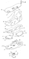
- Anhand der Zeichnung soll die Erfindung in Form eines als Sprengbild dargestellten Ausführungsbeispiels erläutert werden.
- Man erkennt einen üblichen Stiefelschaft 10, gezwickt oder gestrobelt auf eine Brandsohle 20. Unterhalb von Schaft 10 und Brandsohle 20 erkennt man eine Schalensohle 40 mit einem hohen umlaufenden Schalenrand 48, der im Bereich der Zehengrundgelenke einen V-förmigen Einschnitt 49 als Abrollhilfe besitzt. Der Schalenrand 48 wird mit dem Schaft 10 verklebt und soll diesen gegen Feuchtigkeit und Beschädigungen schützen.
- Unter der Schalensohle 40 ist eine Laufsohle 30 montiert.
- Brandsohle 20, Laufsohle 30 und Schalensohle 40 bilden einen flexiblen, dem Anwendungsfall angepaßten Schuhboden, z. B. für einen Trekkingschuh.
- Zwischen Schalensohle 40 und Laufsohle 30 sind im Spitzen- und Fersenbereich biegesteife Verstärkungselemente 50, 55 montiert. Vorne bzw. hinten besitzen die Verstärkungselemente 50, 55 je eine bereichsweise umlaufende Erhöhung 52, 57, und je einen erweiterten Rand 53, 58. Diese ermöglichen die Befestigung von Steigeisen.
- Die Schalensohle 40 weist Aussparungen 42, 47 auf, so daß die Verstärkungselemente 50, 55 Platz finden.
- Wie die Zeichnung erkennen läßt, besitzen Brandsohle 20, Schalensohle 40 und Verstärkungselemente 50, 55 jeweils vier miteinander fluchtende Langlöcher 21, 26; 41, 46; 51, 56, jeweils zwei im Spitzenbereich und im Fersenbereich. In der Laufsohle 30 können passende Vertiefungen 31, 36 vorgesehen sein.
- Brandsohle 20 und Schalensohle 40 besitzen darüber hinaus im Gelenkbereich eine Zentralöffnung 24, 44, die Laufsohle 30 eine mit diesen fluchtende kreisrunde Schloßöffnung 34.
- In die Schloßöffnung ist von der Unterseite der Laufsohle 30 her ein drehbares Schloßelement 70 eingesetzt. Dieses besteht aus einer Haltescheibe 71 mit Drehschlitz 72 auf der Unterseite und einem Riegelzylinder 73 auf der Oberseite. Dieser Zylinder 73 paßt in die Schloßöffnung 34 der Laufsohle 30. Er trägt auf seiner Außenseite einen Vorsprung 75, der mit einer in die Schloßöffnung 34 eingearbeiteten Halte- und Dichtnut 35 korrespondiert. Dank dieser Konstruktion sitzt das Schloßelement 70 dauerhaft in der Schloßöffnung 34.
- Ein aus den bisher beschriebenen Komponenten zusammengebauter Schuh ist ausreichend flexibel. Mit Hilfe einer in den Schuh eingelegten, elastischen Einlage und darauf eines herkömmlichen Fußbetts (beide nicht dargestellt) ist ein langes, ermüdungsfreies, sicheres Gehen und Steigen möglich.
- Sollen unter dem Schuh Steigeisen (nicht dargestellt) montiert werden, nimmt der Bergsteiger Einlage und Fußbett heraus, so daß die Langlöcher 21, 26 und die Zentralöffnung 24 im Schuhboden 20, 40, 50, 55, 30 zugänglich sind. Anschließend schiebt er eine im Rucksack mitgebrachte leichte, jedoch biegesteife Innensohle 60 in den Schuh. Die Innensohle 60 trägt an ihrer Unterseite L-förmige Haken 61, 66, die mit den Langlöchern 21, 26 im Schuhboden 20, 30, 40 fluchten und die sich unter den biegesteifen Verstärkungselementen 50, 55 verhaken, was dank der teilweise aufgebrochenen Darstellung der Innensohle 60 verständlich wird.
- Statt L-förmiger können auch pilzförmige Haken eingesetzt werden, wenn die Langlöcher eine entsprechende Form erhalten.
- Des weiteren trägt die Innensohle 60 auf ihrer Unterseite einen zentralen, T-förmigen Riegel 64, der mit dem Schloßelement 70 korrespondiert. Zum Einsetzen der Innensohle 60 wird das Schloßelement 70 so gedreht, daß sich das auf der Innenseite im Bereich des Dichtzylinders 75 befindende Langloch 74 mit dem Riegel 64 fluchtet. Nach einer 90 Grad-Drehung des Schloßelements 70 ist die Innensohle 60 fest und unverrückbar im Schuh verankert. Nach dem Wiedereinlegen des Fußbetts kann der Bergsteiger den Schuh anziehen und die Steigeisen montieren, deren Bügel an den Verstärkungselementen 50, 55 eingehängt werden.
- Die Innensohle 60 sowie die Verstärkungselemente 50, 55 bestehen aus einem biegesteifen Kunststoff, der zusätzlich mit Glas-, Kevlar- oder Karbonfasern verstärkt sein kann.
- Eine Schlaufe 68 an der Ferse der Innensohle 60 erleichtert das Wieder-Herausnehmen derselben.
- Dank der beschriebenen Konstruktion muß der Bergsteiger für den Fall, daß er Steigeisen benutzen muß, nur noch ein Paar Innensohlen 60 mitführen, deren Gewicht nur wenige 100 Gramm beträgt, während ein Paar herkömmlicher steigeisenfester Stiefel mehrere Kilogramm wiegt und auch erheblich mehr Platz benötigt.
Claims (11)
- Schuhwerk für Sportler wie Bergsteiger, Radfahrer usw., umfassend- einen Schaft (10),- einen elastischen Schuhboden (20, 30, 40) und- ein herausnehmbares Fußbett,gekennzeichnet durch die Merkmale:- es ist eine herausnehmbare, biegesteife Innensohle (60) vorgesehen,- in den Schuhboden (20, 30, 40) sind im Zehenbereich und im Fersen- bzw. Gelenkbereich steife Verstärkungselemente (50, 55) eingearbeitet,- an der Innensohle (60) einerseits und am Schuhboden (20, 30, 40) andererseits sind miteinander korrespondierende Verbindungselemente (31, 34, 36; 41, 44, 46; 51, 56; 61, 64, 66; 70) angebracht, die eine biegesteife, jedoch lösbare Verbindung der Innensohle (60) mit dem Schuhboden (20, 30, 40) ermöglichen.
- Schuhwerk nach Anspruch 1, gekennzeichnet durch die Merkmale:- der Schuhboden besteht aus-- einer Laufsohle (30),-- einer Montage- bzw. Brandsohle (20)-- und gegebenenfalls einer Schalensohle (40) unter der Montage- bzw. Brandsohle (20).
- Schuhwerk nach Anspruch 1 oder 2, gekennzeichnet durch das Merkmal:- die Innensohle (60) und/oder die Verstärkungselemente (50, 55) bestehen aus einem thermo- oder duroplastischen Kunststoff.
- Schuhwerk nach Anspruch 3, gekennzeichnet durch das Merkmal:- die Innensohle (60) und/oder die Verstärkungselemente (50, 55) sind mit Glas-, Kevlar- oder Karbonfasern verstärkt.
- Schuhwerk nach einem der Ansprüche 1 bis 4, gekennzeichnet durch das Merkmal:- die Verstärkungselemente (50, 55) besitzen jeweils vorne bzw. hinten eine bereichsweise Erhöhung (52, 57) und einen verbreiterten Rand (53, 58).
- Schuhwerk nach einem der Ansprüche 1 bis 5, gekennzeichnet durch die Merkmale:- in den Schuhboden (20, 30, 40) und in die Verstärkungselemente (50, 55) sind fluchtende Langlöcher (21, 26; 41, 46; 51, 56) eingearbeitet,- die Innensohle (60) besitzt an ihrer Unterseite im Fersen- und Spitzenbereich mit den Langlöchern (21, 26; 41, 46; 51, 56) fluchtende Haken (61, 66),- die Haken (61, 66) lassen sich unter den Verstärkungselementen (50, 55) einhaken,- im Gelenkbereich von Schuhboden (20, 30, 40) und Innensohle (60) befindet sich eine lösbare Verriegelung (70).
- Schuhwerk nach einem der Ansprüche 1 bis 6, gekennzeichnet durch die Merkmale:- in den Gelenkbereich des Schuhbodens (20, 30, 40) ist eine Zentralöffnung (24, 34, 44) eingearbeitet,- die Innensohle (60) weist im Gelenkbereich einen mit der Zentralöffnung (24, 34, 44) fluchtenden Riegel (64) auf,- in die Zentralöffnung (24, 34, 44) ist ein Schloßelement (70) eingesetzt,-- das mit dem Riegel (64) zusammenwirkt und die Innensohle (60) im Schuh lösbar verriegelt.
- Schuhwerk nach Anspruch 7, gekennzeichnet durch die Merkmale:- die Zentralöffnung (24, 34, 44) ist im Bereich der Laufsohle (30) als Schloßöffnung ausgebildet,-- die Schloßöffnung (34) in der Laufsohle (30) ist kreisrund,-- in ihre Wand ist eine Halte- und Dichtnut (35) eingeformt,- das Schloßelement (70) ist kreisrund,-- besitzt eine außenliegende Halteplatte (71) mit Drehschlitz (72),-- einen Dichtzylinder (73) mit einem Vorsprung (75), korrespondierend mit der Schloßöffnung (34) und-- einen mit dem Riegel (64) in der Innensohle (60) korrespondierenden Verschluß (74).
- Schuhwerk nach einem der Ansprüche 1 bis 6, gekennzeichnet durch die Merkmale:- in den Gelenkbereich des Schuhbodens (20, 30, 40) ist im Schuhinneren eine muldenförmige Vertiefung eingearbeitet,- die Innensohle (60) besitzt an ihrer Unterseite eine mit der Vertiefung korrespondierende Erhöhung.
- Schuhwerk nach einem der Ansprüche 1 bis 9, gekennzeichnet durch das Merkmal:- es ist eine herausnehmbare weiche Einlage von der Größe der Innensohle (60) vorgesehen.
- Schuhwerk nach einem der Ansprüche 2 bis 10, gekennzeichnet durch das Merkmal:- die Schalensohle (40) besitzt einen hohen, umlaufenden Schalenrand (48),- und gegebenenfalls im Bereich der Zehengrundgelenke eine Abrollhilfe (49) in Form eines V-förmigen Einschnitts oder einer Materialverdünnung.
Applications Claiming Priority (2)
| Application Number | Priority Date | Filing Date | Title |
|---|---|---|---|
| DE9417779U DE9417779U1 (de) | 1994-11-05 | 1994-11-05 | Schuhwerk |
| DE9417779U | 1994-11-05 |
Publications (3)
| Publication Number | Publication Date |
|---|---|
| EP0723744A2 true EP0723744A2 (de) | 1996-07-31 |
| EP0723744A3 EP0723744A3 (de) | 1997-06-11 |
| EP0723744B1 EP0723744B1 (de) | 2002-04-10 |
Family
ID=6915761
Family Applications (1)
| Application Number | Title | Priority Date | Filing Date |
|---|---|---|---|
| EP95117412A Expired - Lifetime EP0723744B1 (de) | 1994-11-05 | 1995-11-06 | Schuhwerk |
Country Status (3)
| Country | Link |
|---|---|
| EP (1) | EP0723744B1 (de) |
| AT (1) | ATE215787T1 (de) |
| DE (2) | DE9417779U1 (de) |
Cited By (5)
| Publication number | Priority date | Publication date | Assignee | Title |
|---|---|---|---|---|
| EP0841016A1 (de) * | 1996-11-08 | 1998-05-13 | Salomon S.A. | Verfahren zum Zusammenbau eines Schuhes auf einem Rahmen eines Sportgegenstandes |
| US5887361A (en) * | 1996-11-08 | 1999-03-30 | Salomon S.A. | Sports boot with a mobile collar |
| NL1022921C2 (nl) * | 2003-03-13 | 2004-09-14 | Chen-Yi Yang | Schoenstructuur voorzien van verwisselbare bovenstukken. |
| EP3217828A1 (de) * | 2014-11-13 | 2017-09-20 | Kelteknohow Limited | Bekleidungsartikel |
| CN111163659A (zh) * | 2017-09-20 | 2020-05-15 | 创意鞋履解决方案有限公司 | 模块化鞋系统 |
Families Citing this family (2)
| Publication number | Priority date | Publication date | Assignee | Title |
|---|---|---|---|---|
| DE102021210625A1 (de) | 2021-09-23 | 2023-03-23 | Adidas Ag | Zwischensohle, Schuh, Steigeisenelement und Baugruppe davon |
| IT202200003930U1 (it) * | 2022-09-29 | 2022-12-29 | Palma Massimo Di | Calzature in kit assemblabile e modalità di montaggio |
Family Cites Families (5)
| Publication number | Priority date | Publication date | Assignee | Title |
|---|---|---|---|---|
| FR1014516A (fr) * | 1947-06-23 | 1952-08-18 | Ertekforgalmi Bank R T | Soulier avec partie supérieure remplaçable |
| LU29186A1 (de) * | 1947-11-21 | 1948-10-20 | ||
| BE564142A (de) * | 1957-01-21 | |||
| DE3043425A1 (de) * | 1980-11-18 | 1982-07-15 | Dornseif Sport GmbH, 5608 Radevormwald | Schuh mit an dessen sohle angebrachtem sportgeraet wie schlittschuh, rollschuh o.dgl. |
| IT8642002A0 (it) * | 1986-03-04 | 1986-03-04 | Sarraino Pietro | Calzatura componibile |
-
1994
- 1994-11-05 DE DE9417779U patent/DE9417779U1/de not_active Expired - Lifetime
-
1995
- 1995-11-06 EP EP95117412A patent/EP0723744B1/de not_active Expired - Lifetime
- 1995-11-06 DE DE59510155T patent/DE59510155D1/de not_active Expired - Lifetime
- 1995-11-06 AT AT95117412T patent/ATE215787T1/de not_active IP Right Cessation
Cited By (7)
| Publication number | Priority date | Publication date | Assignee | Title |
|---|---|---|---|---|
| EP0841016A1 (de) * | 1996-11-08 | 1998-05-13 | Salomon S.A. | Verfahren zum Zusammenbau eines Schuhes auf einem Rahmen eines Sportgegenstandes |
| FR2755586A1 (fr) * | 1996-11-08 | 1998-05-15 | Salomon Sa | Procede d'assemblage d'une chaussure a un chassis d'article de sport |
| US5887361A (en) * | 1996-11-08 | 1999-03-30 | Salomon S.A. | Sports boot with a mobile collar |
| US6113123A (en) * | 1996-11-08 | 2000-09-05 | Salomon S.A. | Method for assembling boot components to a chassis of a sports article and the boot/chassis thus assembled |
| NL1022921C2 (nl) * | 2003-03-13 | 2004-09-14 | Chen-Yi Yang | Schoenstructuur voorzien van verwisselbare bovenstukken. |
| EP3217828A1 (de) * | 2014-11-13 | 2017-09-20 | Kelteknohow Limited | Bekleidungsartikel |
| CN111163659A (zh) * | 2017-09-20 | 2020-05-15 | 创意鞋履解决方案有限公司 | 模块化鞋系统 |
Also Published As
| Publication number | Publication date |
|---|---|
| EP0723744A3 (de) | 1997-06-11 |
| DE59510155D1 (de) | 2002-05-16 |
| DE9417779U1 (de) | 1995-01-19 |
| EP0723744B1 (de) | 2002-04-10 |
| ATE215787T1 (de) | 2002-04-15 |
Similar Documents
| Publication | Publication Date | Title |
|---|---|---|
| AT412142B (de) | Snowboardschuh | |
| DE69224050T2 (de) | Mehrschichtige Sportschuhsohle | |
| DE60224264T2 (de) | Kletterschuh mit konkaver sohle | |
| DE60314063T2 (de) | Sportschuh insbesondere für Moto-Cross | |
| DE102008020890A1 (de) | Schuh oder Versteifungselement für Rucksäcke | |
| EP0373336A1 (de) | Einlage für einen Schuh | |
| DE4023659C2 (de) | Langlaufskischuh | |
| DE3043425A1 (de) | Schuh mit an dessen sohle angebrachtem sportgeraet wie schlittschuh, rollschuh o.dgl. | |
| EP0373330A1 (de) | Einlage für einen Schuh | |
| EP0723744B1 (de) | Schuhwerk | |
| DE4329186A1 (de) | Sportschuh mit auswechselbarer Laufsohle | |
| EP0565913B1 (de) | Kletterschuh | |
| DE69106483T2 (de) | Sportschuh, insbesondere für Gehen und Skilanglauf, mit abnehmbarer Schaftmanschette. | |
| DE19847353C2 (de) | Schuh für Gleitsport, insbesondere alpiner Skischuh | |
| EP2505094A2 (de) | Sportschuh, insbesondere alpiner Schischuh | |
| DE19847354B4 (de) | Schuh für Inline-Rollschuh | |
| EP0695513B1 (de) | Mehrzweckschuh | |
| DE8022785U1 (de) | Sportschuh für den Radsport | |
| DE102009022910B3 (de) | Neue Sohle für Schuhe und Sandalen | |
| DE102017000372B4 (de) | Skischuh mit Laufsohle | |
| DE29517869U1 (de) | Schuhsohlenaufbau | |
| DE602004004420T2 (de) | Sportschuh mit hohem Schaft | |
| DE10249033A1 (de) | Überschuh | |
| DE10147660B4 (de) | Schuhwerk für ein Rollsportgerät | |
| DE1888123U (de) | Sportschuh, insbesondere Fußballschuh |
Legal Events
| Date | Code | Title | Description |
|---|---|---|---|
| PUAI | Public reference made under article 153(3) epc to a published international application that has entered the european phase |
Free format text: ORIGINAL CODE: 0009012 |
|
| AK | Designated contracting states |
Kind code of ref document: A2 Designated state(s): AT CH DE FR GB IT LI |
|
| PUAL | Search report despatched |
Free format text: ORIGINAL CODE: 0009013 |
|
| AK | Designated contracting states |
Kind code of ref document: A3 Designated state(s): AT CH DE FR GB IT LI |
|
| RAP1 | Party data changed (applicant data changed or rights of an application transferred) |
Owner name: LOWA SPORTSCHUHE GMBH |
|
| RIN1 | Information on inventor provided before grant (corrected) |
Inventor name: TAVERNAR, GINO |
|
| 17P | Request for examination filed |
Effective date: 19971127 |
|
| 17Q | First examination report despatched |
Effective date: 19990909 |
|
| GRAG | Despatch of communication of intention to grant |
Free format text: ORIGINAL CODE: EPIDOS AGRA |
|
| GRAG | Despatch of communication of intention to grant |
Free format text: ORIGINAL CODE: EPIDOS AGRA |
|
| GRAH | Despatch of communication of intention to grant a patent |
Free format text: ORIGINAL CODE: EPIDOS IGRA |
|
| REG | Reference to a national code |
Ref country code: GB Ref legal event code: IF02 |
|
| GRAH | Despatch of communication of intention to grant a patent |
Free format text: ORIGINAL CODE: EPIDOS IGRA |
|
| GRAA | (expected) grant |
Free format text: ORIGINAL CODE: 0009210 |
|
| AK | Designated contracting states |
Kind code of ref document: B1 Designated state(s): AT CH DE FR GB IT LI |
|
| PG25 | Lapsed in a contracting state [announced via postgrant information from national office to epo] |
Ref country code: IT Free format text: LAPSE BECAUSE OF FAILURE TO SUBMIT A TRANSLATION OF THE DESCRIPTION OR TO PAY THE FEE WITHIN THE PRESCRIBED TIME-LIMIT;WARNING: LAPSES OF ITALIAN PATENTS WITH EFFECTIVE DATE BEFORE 2007 MAY HAVE OCCURRED AT ANY TIME BEFORE 2007. THE CORRECT EFFECTIVE DATE MAY BE DIFFERENT FROM THE ONE RECORDED. Effective date: 20020410 Ref country code: GB Free format text: LAPSE BECAUSE OF FAILURE TO SUBMIT A TRANSLATION OF THE DESCRIPTION OR TO PAY THE FEE WITHIN THE PRESCRIBED TIME-LIMIT Effective date: 20020410 Ref country code: FR Free format text: LAPSE BECAUSE OF FAILURE TO SUBMIT A TRANSLATION OF THE DESCRIPTION OR TO PAY THE FEE WITHIN THE PRESCRIBED TIME-LIMIT Effective date: 20020410 |
|
| REF | Corresponds to: |
Ref document number: 215787 Country of ref document: AT Date of ref document: 20020415 Kind code of ref document: T |
|
| REG | Reference to a national code |
Ref country code: CH Ref legal event code: EP |
|
| REF | Corresponds to: |
Ref document number: 59510155 Country of ref document: DE Date of ref document: 20020516 |
|
| GBV | Gb: ep patent (uk) treated as always having been void in accordance with gb section 77(7)/1977 [no translation filed] |
Effective date: 20020410 |
|
| PG25 | Lapsed in a contracting state [announced via postgrant information from national office to epo] |
Ref country code: AT Free format text: LAPSE BECAUSE OF NON-PAYMENT OF DUE FEES Effective date: 20021106 |
|
| PG25 | Lapsed in a contracting state [announced via postgrant information from national office to epo] |
Ref country code: LI Free format text: LAPSE BECAUSE OF NON-PAYMENT OF DUE FEES Effective date: 20021130 Ref country code: CH Free format text: LAPSE BECAUSE OF NON-PAYMENT OF DUE FEES Effective date: 20021130 |
|
| EN | Fr: translation not filed | ||
| PLBE | No opposition filed within time limit |
Free format text: ORIGINAL CODE: 0009261 |
|
| STAA | Information on the status of an ep patent application or granted ep patent |
Free format text: STATUS: NO OPPOSITION FILED WITHIN TIME LIMIT |
|
| 26N | No opposition filed |
Effective date: 20030113 |
|
| REG | Reference to a national code |
Ref country code: CH Ref legal event code: PL |
|
| PGFP | Annual fee paid to national office [announced via postgrant information from national office to epo] |
Ref country code: DE Payment date: 20140915 Year of fee payment: 20 |
|
| REG | Reference to a national code |
Ref country code: DE Ref legal event code: R071 Ref document number: 59510155 Country of ref document: DE |