EP0719995A2 - Réfrigérateur - Google Patents
Réfrigérateur Download PDFInfo
- Publication number
- EP0719995A2 EP0719995A2 EP95120665A EP95120665A EP0719995A2 EP 0719995 A2 EP0719995 A2 EP 0719995A2 EP 95120665 A EP95120665 A EP 95120665A EP 95120665 A EP95120665 A EP 95120665A EP 0719995 A2 EP0719995 A2 EP 0719995A2
- Authority
- EP
- European Patent Office
- Prior art keywords
- refrigerant
- refrigerator
- air
- detection means
- circulation path
- Prior art date
- Legal status (The legal status is an assumption and is not a legal conclusion. Google has not performed a legal analysis and makes no representation as to the accuracy of the status listed.)
- Granted
Links
Images


Classifications
-
- C—CHEMISTRY; METALLURGY
- C04—CEMENTS; CONCRETE; ARTIFICIAL STONE; CERAMICS; REFRACTORIES
- C04B—LIME, MAGNESIA; SLAG; CEMENTS; COMPOSITIONS THEREOF, e.g. MORTARS, CONCRETE OR LIKE BUILDING MATERIALS; ARTIFICIAL STONE; CERAMICS; REFRACTORIES; TREATMENT OF NATURAL STONE
- C04B41/00—After-treatment of mortars, concrete, artificial stone or ceramics; Treatment of natural stone
- C04B41/45—Coating or impregnating, e.g. injection in masonry, partial coating of green or fired ceramics, organic coating compositions for adhering together two concrete elements
- C04B41/52—Multiple coating or impregnating multiple coating or impregnating with the same composition or with compositions only differing in the concentration of the constituents, is classified as single coating or impregnation
-
- F—MECHANICAL ENGINEERING; LIGHTING; HEATING; WEAPONS; BLASTING
- F25—REFRIGERATION OR COOLING; COMBINED HEATING AND REFRIGERATION SYSTEMS; HEAT PUMP SYSTEMS; MANUFACTURE OR STORAGE OF ICE; LIQUEFACTION SOLIDIFICATION OF GASES
- F25B—REFRIGERATION MACHINES, PLANTS OR SYSTEMS; COMBINED HEATING AND REFRIGERATION SYSTEMS; HEAT PUMP SYSTEMS
- F25B49/00—Arrangement or mounting of control or safety devices
- F25B49/005—Arrangement or mounting of control or safety devices of safety devices
-
- F—MECHANICAL ENGINEERING; LIGHTING; HEATING; WEAPONS; BLASTING
- F25—REFRIGERATION OR COOLING; COMBINED HEATING AND REFRIGERATION SYSTEMS; HEAT PUMP SYSTEMS; MANUFACTURE OR STORAGE OF ICE; LIQUEFACTION SOLIDIFICATION OF GASES
- F25D—REFRIGERATORS; COLD ROOMS; ICE-BOXES; COOLING OR FREEZING APPARATUS NOT OTHERWISE PROVIDED FOR
- F25D17/00—Arrangements for circulating cooling fluids; Arrangements for circulating gas, e.g. air, within refrigerated spaces
- F25D17/04—Arrangements for circulating cooling fluids; Arrangements for circulating gas, e.g. air, within refrigerated spaces for circulating air, e.g. by convection
- F25D17/06—Arrangements for circulating cooling fluids; Arrangements for circulating gas, e.g. air, within refrigerated spaces for circulating air, e.g. by convection by forced circulation
- F25D17/062—Arrangements for circulating cooling fluids; Arrangements for circulating gas, e.g. air, within refrigerated spaces for circulating air, e.g. by convection by forced circulation in household refrigerators
-
- F—MECHANICAL ENGINEERING; LIGHTING; HEATING; WEAPONS; BLASTING
- F25—REFRIGERATION OR COOLING; COMBINED HEATING AND REFRIGERATION SYSTEMS; HEAT PUMP SYSTEMS; MANUFACTURE OR STORAGE OF ICE; LIQUEFACTION SOLIDIFICATION OF GASES
- F25B—REFRIGERATION MACHINES, PLANTS OR SYSTEMS; COMBINED HEATING AND REFRIGERATION SYSTEMS; HEAT PUMP SYSTEMS
- F25B2400/00—General features or devices for refrigeration machines, plants or systems, combined heating and refrigeration systems or heat-pump systems, i.e. not limited to a particular subgroup of F25B
- F25B2400/12—Inflammable refrigerants
-
- F—MECHANICAL ENGINEERING; LIGHTING; HEATING; WEAPONS; BLASTING
- F25—REFRIGERATION OR COOLING; COMBINED HEATING AND REFRIGERATION SYSTEMS; HEAT PUMP SYSTEMS; MANUFACTURE OR STORAGE OF ICE; LIQUEFACTION SOLIDIFICATION OF GASES
- F25B—REFRIGERATION MACHINES, PLANTS OR SYSTEMS; COMBINED HEATING AND REFRIGERATION SYSTEMS; HEAT PUMP SYSTEMS
- F25B2500/00—Problems to be solved
- F25B2500/22—Preventing, detecting or repairing leaks of refrigeration fluids
- F25B2500/222—Detecting refrigerant leaks
-
- F—MECHANICAL ENGINEERING; LIGHTING; HEATING; WEAPONS; BLASTING
- F25—REFRIGERATION OR COOLING; COMBINED HEATING AND REFRIGERATION SYSTEMS; HEAT PUMP SYSTEMS; MANUFACTURE OR STORAGE OF ICE; LIQUEFACTION SOLIDIFICATION OF GASES
- F25D—REFRIGERATORS; COLD ROOMS; ICE-BOXES; COOLING OR FREEZING APPARATUS NOT OTHERWISE PROVIDED FOR
- F25D2400/00—General features of, or devices for refrigerators, cold rooms, ice-boxes, or for cooling or freezing apparatus not covered by any other subclass
- F25D2400/04—Refrigerators with a horizontal mullion
-
- F—MECHANICAL ENGINEERING; LIGHTING; HEATING; WEAPONS; BLASTING
- F25—REFRIGERATION OR COOLING; COMBINED HEATING AND REFRIGERATION SYSTEMS; HEAT PUMP SYSTEMS; MANUFACTURE OR STORAGE OF ICE; LIQUEFACTION SOLIDIFICATION OF GASES
- F25D—REFRIGERATORS; COLD ROOMS; ICE-BOXES; COOLING OR FREEZING APPARATUS NOT OTHERWISE PROVIDED FOR
- F25D2700/00—Means for sensing or measuring; Sensors therefor
- F25D2700/02—Sensors detecting door opening
Definitions
- the present invention relates to a refrigerator employing a refrigerant that is not harmful to global environment.
- CFC chlorofluorocarbon
- hydrofluorocarbon (HFC)-based refrigerants do not damage the ozone layer. They, however, promote a greenhouse effect, and therefore, European countries, in particular, plan to prohibit the use of the HFC-based refrigerants. Namely, artificially produced CFC- and HFC-based refrigerants will be prohibited from use and natural refrigerants such as hydrocarbon refrigerants will be accepted.
- HFC hydrofluorocarbon
- hydrocarbon refrigerants are unharmful to environment, they are flammable. If they leak, they may explode. It is difficult to secure the safety of use of the hydrocarbon refrigerants.
- An object of the present invention is to provide a refrigerator employing a flammable refrigerant that is unharmful to environment, capable of securing the safety of use of the flammable refrigerant.
- Another object of the present invention is to provide a refrigerator employing a flammable refrigerant, capable of quickly stopping the operation thereof if the refrigerant leaks.
- Still another object of the present invention is to provide a refrigerator employing a flammable refrigerant, capable of quickly diffusing the refrigerant to avoid explosion if the refrigerant leaks.
- an aspect of the present invention provides a refrigerator having a compressor 17 for compressing a flammable refrigerant, a cooling fan 15, a condenser 11 for condensing and air-cooling the compressed refrigerant, an evaporator 25 for vaporizing the condensed refrigerant to chill air, a circulation path for circulating the chilled air inside the refrigerator, an inside fan 27 for circulating the chilled air through the circulation path, leak detectors S3 and S4 for detecting a leak of the refrigerant, and a controller 34 for stopping the compressor 17 if the detectors detect a leak of the refrigerant.
- the controller 34 may stop the inside fan 27 when the detectors S3 and S4 detect a leak of the refrigerant.
- the compressor 17 and cooling fan 15 may be driven and controlled independently of each other.
- the refrigerator may have shutoff unit s39 for stopping the chilled air from entering the circulation path if the detectors S3 and S4 detect a leak of the refrigerant.
- the shutoff units 39 may be shutters disposed at the entrance and exit of the circulation path.
- Still another aspect of the present invention provides a refrigerator having a compressor 17 for compressing a flammable refrigerant, a cooling fan 15, a condenser 11 for condensing and air-cooling the compressed refrigerant, an evaporator 25 for vaporizing the condensed refrigerant to chill air, a circulation path for circulating the chilled air inside the refrigerator, an inside fan 27 for circulating the chilled air through the circulation path, leak detectors S3 and S4 for detecting a leak of the refrigerant, and a unit for restarting the cooling fan 15 after the cooling fan 15 is stopped for a given period.
- the rotation speed of the cooling fan 15 is higher in a refrigeration cycle than in a stoppage of the refrigeration cycle.
- Still another aspect of the present invention provides a refrigerator having a compressor 17 for compressing a flammable refrigerant, a cooling fan 15, a condenser 11 for condensing and air-cooling the compressed refrigerant, an evaporator 25 for vaporizing the condensed refrigerant to chill air, a circulation path for circulating the chilled air inside the refrigerator, an inside fan 27 for circulating the chilled air through the circulation path, leak detectors S3 and S4 for detecting a leak of the refrigerant, and a unit 47 for withdrawing the refrigerant if the detectors detect a leak of the refrigerant.
- Still another aspect of the present invention provides a refrigerator having a compressor 17 for compressing a flammable refrigerant, a cooling fan 15, a condenser 11 for condensing and air-cooling the compressed refrigerant, an evaporator 25 for vaporizing the condensed refrigerant to chill air, a circulation path for circulating the chilled air inside the refrigerator, an inside fan 27 for circulating the chilled air through the circulation path, and a unit for driving the inside fan 27 for a predetermined period after a door of the refrigerator is opened and stopping the inside fan 27 after the predetermined period.
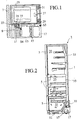
- FIGS 1 and 2 show a refrigerator 3 according to an embodiment of the present invention.
- the refrigerator 3 has a main body 1 having doors 5.
- a lower part of the main body 1 includes a partitioned chamber 7 and a mechanical chamber 9.
- the chamber 7 is for a refrigeration cycle.
- the mechanical chamber 9 accommodates a condenser 11, an evaporation plate 13, a cooling fan 15, a compressor 17, an accumulator 19, and a choke (capillary tube) 21.
- the accumulator 19 and choke 21 are accommodated in an independent chamber 23. In this way, devices that involve piping and connections are arranged outside the chamber 7.
- the chamber 7 includes an evaporator 25, an inside fan 27, an exit 29 for chilled air, and an entrance 31 for return air.
- the exit 29 and entrance 31 are connected to a circulation duct 33, which communicates with the inside 35 of the refrigerator 3.
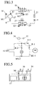
- Figure 3 shows the refrigeration cycle employing a natural refrigerant made of hydrocarbons such as propane and isobutane. These hydrocarbons are flammable, and therefore, it is important to secure the safety of use of them.
- hydrocarbons such as propane and isobutane.
- the compressor 17 discharges the refrigerant, which passes through the condenser 11, choke 21, and evaporator 25 and returns to the compressor 17.
- the evaporator 25 has fins to absorb latent heat from environmental air, to thereby chill the air. The chilled air is blown by the inside fan 27 into the exit 29.
- Figure 4 shows a motor M1 for driving the compressor 17 and a motor M2 for driving the cooling fan 15.
- the motor M1 is turned ON and OFF by a drive circuit M1-1, and the motor M2 by a drive circuit M2-2.
- the drive circuit M1-1 has a contact R-1, and the drive circuit M2-2 has a contact R-2. These contacts are opened and closed by a controller 34.
- a thermal switch S-1 opens the contact R-1 without regard to a signal from the controller 34.
- a detector S1 detects an abnormality in the motor M1.
- a detector S2 detects an abnormality in the motor M2.
- Detectors S3 and S4 detect a leak of the refrigerant.
- the controller 34 receives signals from the detectors S1 to S4, carries out necessary operations, and provides instruction signals.
- An abnormality of the motors M1 and M2 may be detected according to the insulation resistance of a motor power source, a motor revolution speed, or the temperature of a coil.
- the controller 34 Upon receiving an abnormality signal from any one of the detectors S1 and S2 of the motors M1 and M2, the controller 34 opens the contact R-1 of the compressor drive circuit M1-1, or the contact R-2 of the cooling fan drive circuit M2-2.
- the detector S3 is arranged on the downstream of the evaporator 25 in a flow of air crossing the evaporator 25.
- the detector S4 is arranged on the downstream of the condenser 11 in a flow of air crossing the condenser 11.
- the detectors S3 and S4 may be arranged around the piping and connections including the accumulator 19, or at a position S5 on the downstream of the compressor 17 in a flow of air crossing the compressor 17, or at a position S6 in the vicinity of the exit 29.
- the detectors S3 and S4 may be oxygen sensors that detect oxygen in the refrigerant that flows in the refrigeration cycle. Namely, when the refrigerant leaks, oxygen enters in the refrigeration cycle, and the oxygen sensors detect such oxygen. Signals from the oxygen sensors are received by the controller 34.
- the controller 34 Upon receiving a leak signal from any one of the detectors S3 and S4 during a refrigeration cycle, the controller 34 opens the contact R-1 of the compressor drive circuit M1-1 and closes the contact R-2 of the cooling fan drive circuit M2-2. At the same time, the controller 34 turns ON an alarm 37, which may be an alarm buzzer or lamp. In addition, the controller 34 stops the inside fan 27 and closes shutoff valves a and b.
- the shutoff valve a is arranged between the choke 21 and the evaporator 25, and the shutoff valve b is arranged between the evaporator 25 and the compressor 17 as shown in Fig. 3.
- the controller 34 Upon receiving a leak signal from any one of the detectors S3 and S4 during the stoppage of the refrigeration cycle, the controller 34 closes the contact R-2 of the cooling fan drive circuit M2-2 and turns ON the alarm 37. At this time, the cooling fan 15 is used to diffuse the leaked refrigerant, and therefore, it is driven at a low speed through, for example, an inverter controller, to reduce energy consumption and noise.
- FIGS. 6 and 7 are flowcharts showing the operations of the shutoff valves a and b.
- Figure 7 shows the steps of detecting a leak of refrigerant from the high-pressure condenser 11.
- the detector S4 detects a leak of the refrigerant.
- the controller 34 opens the contact R-1 of the compressor drive circuit M1-1, to stop the compressor 17.
- a pressure sensor S7 disposed at the discharge side of the compressor 17 provides a discharge pressure Pd, and it is determined whether or not Pd is below a given value. If it is below the given value, step 104 closes the shutoff valves a and b to block the flow of the refrigerant.
- the given value compared with the discharge pressure Pd is a saturation pressure of the refrigerant under a normal ambient temperature, preferably, a saturation pressure of the refrigerant under a temperature of ambient temperature plus 5 degrees centigrade.
- Figure 6 shows the steps of detecting a leak of the refrigerant from the evaporator 25 that operates at a low pressure.
- the detector S3 detects a leak of the refrigerant.
- the controller 34 stops the inside fan 27 in step 202 and the compressor 17 in step 203, and closes the shutoff valves a and b in step 204. As a result, no refrigerant is sent into the inside 35, and the flammable refrigerant is confined in the piping and evaporator 25.
- Figure 8 shows a shutter 39 arranged at each of the exit 29 and entrance 31, to shut off chilled air.
- the shutter 39 is opened and closed by a cam 43 that is driven by a motor 41.
- Figure 9 shows the operation of the shutter 39.
- the detectors S3 and S4 monitor a leak of the refrigerant in step 301. If one of them detects a leak, the controller 34 turns ON the motor 41 in step 302, to close the shutters 39 in step 303, and turns ON the alarm 37 in step 304. As a result, the path communicating with the inside 35 is blocked.
- the shutters 39 are not limited to those driven by cams.
- Figure 10 shows a bellows 45 that is driven by the discharge pressure of the compressor 17, to open the shutter 39.
- Fig. 11 shows the operation of the bellows 45.
- the detectors S3 and S4 monitor a leak of the refrigerant in step 401. If one of them detects a leak, the controller 34 stops the compressor 17 in step 402, expands the bellows 45 in step 403, to close the shutters 39 in step 404, and turns ON the alarm 37 in step 405. As a result, the path communicating with the inside 35 is blocked.
- Figure 12 shows a unit for withdrawing the refrigerant from the refrigeration cycle if the refrigerant leaks.
- the refrigeration cycle is formed of the compressor 17, condenser 11, choke 21, and evaporator 25.
- a withdrawal tank 47 for withdrawing the refrigerant is arranged in parallel with the condenser 11 on the discharge side of the compressor 17.
- a shutoff valve c stops the flow of the refrigerant to the condenser 11, and a shutoff valve d stops the flow of the refrigerant to the tank 47.
- the tank 47 is positioned on the downstream of the cooling fan 15 so that the tank 47 is cooled to withdraw the refrigerant.
- FIG 14 shows an arrangement for cooling the withdrawal tank 47.
- the tank 47 is installed in a cooling tank 55.
- the cooling tank 55 is filled with a liquid coolant 53 such as liquid CO2 and is surrounded by a heat insulation material 51.
- a capillary tube 57 is wound around the tank 47. An end of the tube 57 is open to the inside of the cooling tank 55, and the other end thereof is closed by a valve e outside the cooling tank 55. When the valve e is opened, the liquid coolant 53 is vaporized and released to the atmosphere, to thereby rapidly decrease the temperature of the tank 47.
- FIG. 13 is a flowchart showing the operations of the valves c, d, and e.
- the detectors S3 and S4 monitor a leak of the refrigerant. If one of them detects a leak, the controller 34 closes the valve c and opens the valve d in step 502. As a result, the refrigerant from the compressor 17 is fed into the withdrawal tank 47, and therefore, the liquid coolant 53 is vaporized to increase the pressure of the cooling tank 55. Then, the controller 34 opens the valve e in step 503 to cool the tank 47 due to a sudden expansion of the liquid coolant 53 in the tank 55. At this time, the high-pressure refrigerant in the tank 47 is liquefied to reduce the pressure thereof. In this way, the refrigerant is collected and liquefied in the tank 47.
- Step 504 determines whether or not the discharge pressure Pd of the compressor 17 detected by the pressure sensor S7 is below a given value. If the pressure Pd is below the given value, step 505 closes the valve d, and step 506 stops the compressor 17.
- FIG. 15 shows a refrigerator capable of safely using a flammable refrigerant according to another embodiment of the present invention.
- the refrigerator has a door 5 having a switch 59 for detecting whether or not the door 5 is open.
- an inside fan 27 is turned ON/OFF.
- FIG 16 is a flowchart showing the operations of the inside fan 27 and switch 59.
- Step 601 determines whether the switch 59 is ON or OFF, i.e., whether the door 5 is opened or closed. If the door 5 is opened, step 602 determines whether or not the door 5 has been opened for a given period. If YES, step 603 stops the inside fan 27. If the refrigerant leaks into the inside 35 of the refrigerator, the inside fan 27 diffuses the leaked refrigerant and purges the same outside through the opened door 5 so that the concentration of the leaked refrigerant may not reach a flammable level.
- the cooling fan 15 may be operated at a low speed depending on the temperature of the condenser 11 or an ambient temperature.
- Figure 17 is a flowchart showing the normal-and low-speed operations of the cooling fan 15.
- Step 701 determines whether or not the compressor 17 is ON. If it is stopped, step 702 counts a period for which the fan 15 is stopped. Step 703 determines whether or not the stop period of the fan 15 has reached a given value, and if not, step 702 is repeated. If step 703 provides YES, step 704 drives the fan 15 for a predetermined period at a low speed.
- step 705 determines whether or not the temperature of the condenser 11 is below a given value. If it is above the given value, step 706 drives the fan 15 at a normal speed. If it is below the given value, step 707 determines whether or not an ambient temperature is below a given value. If it is below the given value, step 708 drives the fan 15 at a low speed. If it is above the given value, step 706 drives the fan 15 at the normal speed.
- the compressor 17 discharges the refrigerant, which passes through the condenser 11, choke 21, and evaporator 25 and returns to the compressor 17.
- the evaporator 25 has fins to absorb latent heat from environmental air, to thereby chill the air.
- the chilled air is blown by the inside fan 27 into the inside 35 of the refrigerator.
- the inside fan 27 is stopped to prevent the leaked refrigerant from entering the inside 35 of the refrigerator. Then, the embodiment of Figs. 3 and 12 withdraws the refrigerant into the tank 47 and confines the refrigerant in the evaporator 25 with the shutoff valves. Accordingly, the concentration of the leaked refrigerant will never reach a flammable level, to thereby secure the safety of use of the flammable refrigerant.
- the cooling fan 15 is operated at a low speed to diffuse the leaked refrigerant so that the concentration thereof may not reach a flammable or explosion level.
- the inside fan 27 is driven for a predetermined period when the door 5 is opened to diffuse and purge the refrigerant leaked inside the refrigerator.
- the present invention surely detects a leak of refrigerant in a refrigerator and prevents the leaked refrigerant from entering the inside of the refrigerator.
- the leaked refrigerant is diffused so that the concentration of the leaked refrigerant may not reach a flammable level.
- the present invention secures the safety of use of a flammable refrigerant and prevents combustion or explosion even if the refrigerant leaks.
Landscapes
- Engineering & Computer Science (AREA)
- Chemical & Material Sciences (AREA)
- Ceramic Engineering (AREA)
- Physics & Mathematics (AREA)
- Mechanical Engineering (AREA)
- Thermal Sciences (AREA)
- General Engineering & Computer Science (AREA)
- Materials Engineering (AREA)
- Structural Engineering (AREA)
- Organic Chemistry (AREA)
- Combustion & Propulsion (AREA)
- Devices That Are Associated With Refrigeration Equipment (AREA)
Applications Claiming Priority (3)
| Application Number | Priority Date | Filing Date | Title |
|---|---|---|---|
| JP328974/94 | 1994-12-28 | ||
| JP32897494 | 1994-12-28 | ||
| JP32897494A JP3452666B2 (ja) | 1994-12-28 | 1994-12-28 | 冷凍冷蔵庫 |
Publications (3)
| Publication Number | Publication Date |
|---|---|
| EP0719995A2 true EP0719995A2 (fr) | 1996-07-03 |
| EP0719995A3 EP0719995A3 (fr) | 2000-10-11 |
| EP0719995B1 EP0719995B1 (fr) | 2004-07-28 |
Family
ID=18216201
Family Applications (1)
| Application Number | Title | Priority Date | Filing Date |
|---|---|---|---|
| EP19950120665 Expired - Lifetime EP0719995B1 (fr) | 1994-12-28 | 1995-12-28 | Réfrigérateur |
Country Status (3)
| Country | Link |
|---|---|
| EP (1) | EP0719995B1 (fr) |
| JP (1) | JP3452666B2 (fr) |
| DE (1) | DE69533303T2 (fr) |
Cited By (17)
| Publication number | Priority date | Publication date | Assignee | Title |
|---|---|---|---|---|
| EP0881393A1 (fr) * | 1995-12-05 | 1998-12-02 | Matsushita Electric Industrial Co., Ltd. | Compresseur hermétique et dispositifs de réfrigération par conditionnement de l'air l'utilisant |
| WO2003029733A1 (fr) * | 2001-09-28 | 2003-04-10 | Kabushiki Kaisha Toshiba | Refrigerateur |
| WO2003038352A1 (fr) | 2001-11-01 | 2003-05-08 | Kabushiki Kaisha Toshiba | Refrigerateur |
| EP1471312A2 (fr) * | 1998-02-13 | 2004-10-27 | Matsushita Electric Industrial Co., Ltd. | Dispositif de détection de fuite de réfrigérant utilisant un réfrigérant inflammable |
| EP1475588A1 (fr) * | 2002-01-15 | 2004-11-10 | Kabushiki Kaisha Toshiba | Refrigerateur muni d'un systeme d'alerte pour signaler une fuite d'agent refrigerant |
| US9353979B2 (en) | 2008-10-29 | 2016-05-31 | Mitsubishi Electric Corporation | Air-conditioning apparatus |
| EP3115716A4 (fr) * | 2014-02-21 | 2018-02-21 | Daikin Industries, Ltd. | Dispositif de climatisation |
| CN109708247A (zh) * | 2018-12-11 | 2019-05-03 | 宁波奥克斯电气股份有限公司 | 一种可燃性冷媒泄露的控制方法、控制装置和空调器 |
| EP3502581A1 (fr) * | 2017-12-22 | 2019-06-26 | Thomas Roggenkamp | Armoire climatisée et système de récupération de chaleur |
| CN111256427A (zh) * | 2020-01-19 | 2020-06-09 | 新誉防务技术有限公司 | 舰用冷藏装置冷媒泄漏的判断方法及判断系统 |
| CN112503720A (zh) * | 2020-12-08 | 2021-03-16 | 合肥美的暖通设备有限公司 | 冷媒泄漏保护方法、空气调节设备和可读存储介质 |
| WO2021050699A1 (fr) * | 2019-09-12 | 2021-03-18 | Carrier Corporation | Purge de réfrigérant de mise en marche ou de coupure de courant initiale |
| US11060775B2 (en) * | 2017-03-09 | 2021-07-13 | Lennox Industries Inc. | Method and apparatus for refrigerant leak detection |
| US11287153B2 (en) | 2019-12-02 | 2022-03-29 | Lennox Industries Inc. | Method and apparatus for risk reduction during refrigerant leak |
| EP3290839B1 (fr) * | 2016-08-29 | 2022-04-13 | Liebherr-Hausgeräte Ochsenhausen GmbH | Appareil de réfrigération et/ou de congélation |
| US11441820B2 (en) | 2018-09-06 | 2022-09-13 | Carrier Corporation | Refrigerant leak detection system |
| US20230392817A1 (en) * | 2022-06-07 | 2023-12-07 | Johnson Controls Tyco IP Holdings LLP | Working fluid eliminator for a heating, ventilation, and/or air conditioning (hvac) system |
Families Citing this family (9)
| Publication number | Priority date | Publication date | Assignee | Title |
|---|---|---|---|---|
| JPH11351711A (ja) * | 1998-06-11 | 1999-12-24 | Sanyo Electric Co Ltd | 冷媒回収装置を備えた冷凍装置 |
| JP4200249B2 (ja) * | 1999-10-01 | 2008-12-24 | パナソニック株式会社 | 冷蔵庫 |
| JP3661548B2 (ja) * | 2000-02-25 | 2005-06-15 | 三菱電機株式会社 | 可燃性冷媒を用いた冷蔵庫 |
| JP4270789B2 (ja) * | 2002-01-17 | 2009-06-03 | 株式会社東芝 | 冷蔵庫 |
| KR100474329B1 (ko) * | 2002-05-07 | 2005-03-08 | 엘지전자 주식회사 | 냉장고의 압축기 운전제어방법 |
| JP2006044424A (ja) | 2004-08-03 | 2006-02-16 | Sanden Corp | 車両用空調装置 |
| JP5619664B2 (ja) * | 2011-03-31 | 2014-11-05 | ホシザキ電機株式会社 | 製氷機 |
| JP7340215B2 (ja) * | 2017-11-28 | 2023-09-07 | 新星冷蔵工業株式会社 | 冷却システム |
| US10794629B2 (en) | 2018-06-29 | 2020-10-06 | Midea Group Co., Ltd. | Negative pressure sensing for an appliance door closure |
Citations (8)
| Publication number | Priority date | Publication date | Assignee | Title |
|---|---|---|---|---|
| US2894378A (en) * | 1957-05-17 | 1959-07-14 | Gen Motors Corp | Refrigerating apparatus |
| US4253130A (en) * | 1979-06-08 | 1981-02-24 | Robertshaw Controls Company | Method and apparatus for heat pump system protection |
| WO1982003269A1 (fr) * | 1981-03-16 | 1982-09-30 | Robert J Cantley | Systeme de gestion de l'energie pour systemes de refrigeration |
| US4890459A (en) * | 1988-12-08 | 1990-01-02 | Thermo King Corporation | Monitor for refrigeration system |
| GB2260816A (en) * | 1991-10-21 | 1993-04-28 | Para Mech Limited | Monitoring fluid quantities |
| DE4207859A1 (de) * | 1992-03-12 | 1993-09-16 | Bayerische Motoren Werke Ag | Kaeltemittelkreislauf einer fahrzeug-klimaanlage |
| US5289162A (en) * | 1992-07-27 | 1994-02-22 | Mcdaniel Steven M | Emergency condition and door ajar alarm for appliances |
| DE4318271A1 (de) * | 1993-06-02 | 1994-12-08 | Miele & Cie | Kühlschrank, insbesondere Haushaltkühlschrank mit Sicherheitseinrichtung |
Family Cites Families (20)
| Publication number | Priority date | Publication date | Assignee | Title |
|---|---|---|---|---|
| JPS5510842Y2 (fr) * | 1974-12-11 | 1980-03-10 | ||
| JPS5854905U (ja) * | 1981-10-13 | 1983-04-14 | 三菱重工業株式会社 | 自動車用空調機 |
| JPH0240461Y2 (fr) * | 1984-10-23 | 1990-10-29 | ||
| JPS6269767U (fr) * | 1985-10-21 | 1987-05-01 | ||
| JPS62199979A (ja) * | 1986-02-28 | 1987-09-03 | Mitsubishi Electric Corp | 分離形空気調和機の制御装置 |
| JPS62164563U (fr) * | 1986-04-07 | 1987-10-19 | ||
| JPS6445267U (fr) * | 1987-09-09 | 1989-03-17 | ||
| JPH01102672U (fr) * | 1987-12-28 | 1989-07-11 | ||
| JPH02157495A (ja) * | 1988-12-09 | 1990-06-18 | Fujitsu General Ltd | 空気調和機のファンモータの異常検出方法 |
| JPH0749306Y2 (ja) * | 1988-12-31 | 1995-11-13 | ダイキン工業株式会社 | 空気調和装置の保護装置 |
| JPH03213972A (ja) * | 1990-01-19 | 1991-09-19 | Matsushita Refrig Co Ltd | 冷蔵庫 |
| JPH0824409B2 (ja) * | 1990-05-07 | 1996-03-06 | ダイキン工業株式会社 | モータの制御装置 |
| JPH0460360A (ja) * | 1990-06-28 | 1992-02-26 | Toshiba Corp | 空気調和装置 |
| JP3162132B2 (ja) * | 1991-10-30 | 2001-04-25 | 株式会社日立製作所 | 冷凍装置の制御方法 |
| JPH05164437A (ja) * | 1991-12-12 | 1993-06-29 | Hitachi Ltd | 空気調和機 |
| JP2924445B2 (ja) * | 1992-04-03 | 1999-07-26 | ダイキン工業株式会社 | 空気調和機用圧縮機の駆動装置 |
| JP3237218B2 (ja) * | 1992-08-05 | 2001-12-10 | 株式会社日立製作所 | 空気調和装置 |
| JPH06123530A (ja) * | 1992-10-08 | 1994-05-06 | Mitsubishi Heavy Ind Ltd | 冷凍ユニットの絶縁診断装置 |
| JPH06180166A (ja) * | 1992-12-09 | 1994-06-28 | Toshiba Corp | 空気調和機 |
| JPH06185849A (ja) * | 1992-12-18 | 1994-07-08 | Fujitsu General Ltd | 電気冷蔵庫の制御装置 |
-
1994
- 1994-12-28 JP JP32897494A patent/JP3452666B2/ja not_active Expired - Lifetime
-
1995
- 1995-12-28 EP EP19950120665 patent/EP0719995B1/fr not_active Expired - Lifetime
- 1995-12-28 DE DE1995633303 patent/DE69533303T2/de not_active Expired - Fee Related
Patent Citations (8)
| Publication number | Priority date | Publication date | Assignee | Title |
|---|---|---|---|---|
| US2894378A (en) * | 1957-05-17 | 1959-07-14 | Gen Motors Corp | Refrigerating apparatus |
| US4253130A (en) * | 1979-06-08 | 1981-02-24 | Robertshaw Controls Company | Method and apparatus for heat pump system protection |
| WO1982003269A1 (fr) * | 1981-03-16 | 1982-09-30 | Robert J Cantley | Systeme de gestion de l'energie pour systemes de refrigeration |
| US4890459A (en) * | 1988-12-08 | 1990-01-02 | Thermo King Corporation | Monitor for refrigeration system |
| GB2260816A (en) * | 1991-10-21 | 1993-04-28 | Para Mech Limited | Monitoring fluid quantities |
| DE4207859A1 (de) * | 1992-03-12 | 1993-09-16 | Bayerische Motoren Werke Ag | Kaeltemittelkreislauf einer fahrzeug-klimaanlage |
| US5289162A (en) * | 1992-07-27 | 1994-02-22 | Mcdaniel Steven M | Emergency condition and door ajar alarm for appliances |
| DE4318271A1 (de) * | 1993-06-02 | 1994-12-08 | Miele & Cie | Kühlschrank, insbesondere Haushaltkühlschrank mit Sicherheitseinrichtung |
Cited By (26)
| Publication number | Priority date | Publication date | Assignee | Title |
|---|---|---|---|---|
| EP0881393A1 (fr) * | 1995-12-05 | 1998-12-02 | Matsushita Electric Industrial Co., Ltd. | Compresseur hermétique et dispositifs de réfrigération par conditionnement de l'air l'utilisant |
| EP1471312A2 (fr) * | 1998-02-13 | 2004-10-27 | Matsushita Electric Industrial Co., Ltd. | Dispositif de détection de fuite de réfrigérant utilisant un réfrigérant inflammable |
| EP1471312A3 (fr) * | 1998-02-13 | 2005-01-19 | Matsushita Electric Industrial Co., Ltd. | Dispositif de détection de fuite de réfrigérant utilisant un réfrigérant inflammable |
| WO2003029733A1 (fr) * | 2001-09-28 | 2003-04-10 | Kabushiki Kaisha Toshiba | Refrigerateur |
| US6923015B2 (en) | 2001-09-28 | 2005-08-02 | Kabushiki Kaisha Toshiba | Refrigerator |
| CN1324285C (zh) * | 2001-09-28 | 2007-07-04 | 株式会社东芝 | 电冰箱 |
| WO2003038352A1 (fr) | 2001-11-01 | 2003-05-08 | Kabushiki Kaisha Toshiba | Refrigerateur |
| EP1452809A1 (fr) * | 2001-11-01 | 2004-09-01 | Kabushiki Kaisha Toshiba | Refrigerateur |
| EP1452809A4 (fr) * | 2001-11-01 | 2008-05-14 | Toshiba Kk | Refrigerateur |
| EP1475588A1 (fr) * | 2002-01-15 | 2004-11-10 | Kabushiki Kaisha Toshiba | Refrigerateur muni d'un systeme d'alerte pour signaler une fuite d'agent refrigerant |
| EP1475588A4 (fr) * | 2002-01-15 | 2008-04-09 | Toshiba Kk | Refrigerateur muni d'un systeme d'alerte pour signaler une fuite d'agent refrigerant |
| US9353979B2 (en) | 2008-10-29 | 2016-05-31 | Mitsubishi Electric Corporation | Air-conditioning apparatus |
| EP3115716A4 (fr) * | 2014-02-21 | 2018-02-21 | Daikin Industries, Ltd. | Dispositif de climatisation |
| EP3290839B1 (fr) * | 2016-08-29 | 2022-04-13 | Liebherr-Hausgeräte Ochsenhausen GmbH | Appareil de réfrigération et/ou de congélation |
| US11060775B2 (en) * | 2017-03-09 | 2021-07-13 | Lennox Industries Inc. | Method and apparatus for refrigerant leak detection |
| US11644225B2 (en) | 2017-03-09 | 2023-05-09 | Lennox Industries Inc. | Method and apparatus for refrigerant leak detection |
| US20210293431A1 (en) * | 2017-03-09 | 2021-09-23 | Lennox Industries Inc. | Method and apparatus for refrigerant leak detection |
| EP3502581A1 (fr) * | 2017-12-22 | 2019-06-26 | Thomas Roggenkamp | Armoire climatisée et système de récupération de chaleur |
| US11441820B2 (en) | 2018-09-06 | 2022-09-13 | Carrier Corporation | Refrigerant leak detection system |
| CN109708247A (zh) * | 2018-12-11 | 2019-05-03 | 宁波奥克斯电气股份有限公司 | 一种可燃性冷媒泄露的控制方法、控制装置和空调器 |
| WO2021050699A1 (fr) * | 2019-09-12 | 2021-03-18 | Carrier Corporation | Purge de réfrigérant de mise en marche ou de coupure de courant initiale |
| US11287153B2 (en) | 2019-12-02 | 2022-03-29 | Lennox Industries Inc. | Method and apparatus for risk reduction during refrigerant leak |
| US11788751B2 (en) | 2019-12-02 | 2023-10-17 | Lennox Industries Inc. | Method and apparatus for risk reduction during refrigerant leak |
| CN111256427A (zh) * | 2020-01-19 | 2020-06-09 | 新誉防务技术有限公司 | 舰用冷藏装置冷媒泄漏的判断方法及判断系统 |
| CN112503720A (zh) * | 2020-12-08 | 2021-03-16 | 合肥美的暖通设备有限公司 | 冷媒泄漏保护方法、空气调节设备和可读存储介质 |
| US20230392817A1 (en) * | 2022-06-07 | 2023-12-07 | Johnson Controls Tyco IP Holdings LLP | Working fluid eliminator for a heating, ventilation, and/or air conditioning (hvac) system |
Also Published As
| Publication number | Publication date |
|---|---|
| DE69533303T2 (de) | 2005-07-21 |
| EP0719995A3 (fr) | 2000-10-11 |
| JP3452666B2 (ja) | 2003-09-29 |
| JPH08178481A (ja) | 1996-07-12 |
| EP0719995B1 (fr) | 2004-07-28 |
| DE69533303D1 (de) | 2004-09-02 |
Similar Documents
| Publication | Publication Date | Title |
|---|---|---|
| EP0719995B1 (fr) | Réfrigérateur | |
| KR100197697B1 (ko) | 냉장실의 내기온도 상승방지 장치 및 방법 | |
| US20050086952A1 (en) | Refrigerator-freezer controller of refrigenator-freezer, and method for determination of leakage of refrigerant | |
| US20210293460A1 (en) | Container refrigeration apparatus | |
| JP4038830B2 (ja) | 冷蔵庫 | |
| KR100639716B1 (ko) | 냉장고 | |
| US6105377A (en) | Air curtain fan driving device and method for a refrigerator | |
| JPH11211293A (ja) | 冷蔵庫 | |
| US20050150246A1 (en) | Refrigerating equipment | |
| KR101450664B1 (ko) | 냉장고의 제상장치 및 제상방법 | |
| JP2000006801A (ja) | 鉄道車両用空調装置 | |
| JP2000146393A (ja) | 冷凍装置 | |
| JP3712126B2 (ja) | 冷凍冷蔵庫 | |
| JP2000097530A (ja) | 冷却貯蔵庫 | |
| JP4120181B2 (ja) | 加熱用ヒータの設置方法 | |
| JP2002195724A (ja) | 冷蔵庫 | |
| JP2003214743A (ja) | 冷蔵庫 | |
| JP3745341B2 (ja) | 冷凍冷蔵庫 | |
| JP3357845B2 (ja) | 冷却貯蔵庫 | |
| JP2005331187A (ja) | 冷蔵庫 | |
| JP3713948B2 (ja) | 冷蔵庫 | |
| JPH10103838A (ja) | 冷凍冷蔵庫 | |
| KR100226802B1 (ko) | 냉장고의 급속동결장치 | |
| JP2007292460A (ja) | 冷蔵庫、加熱用ヒータの設置方法。 | |
| KR19990061263A (ko) | 냉장고의 메인 피씨비의 이슬방지 제어방법 |
Legal Events
| Date | Code | Title | Description |
|---|---|---|---|
| PUAI | Public reference made under article 153(3) epc to a published international application that has entered the european phase |
Free format text: ORIGINAL CODE: 0009012 |
|
| 17P | Request for examination filed |
Effective date: 19951228 |
|
| AK | Designated contracting states |
Kind code of ref document: A2 Designated state(s): DE FR GB IT |
|
| PUAL | Search report despatched |
Free format text: ORIGINAL CODE: 0009013 |
|
| AK | Designated contracting states |
Kind code of ref document: A3 Designated state(s): DE FR GB IT |
|
| 17Q | First examination report despatched |
Effective date: 20020723 |
|
| GRAP | Despatch of communication of intention to grant a patent |
Free format text: ORIGINAL CODE: EPIDOSNIGR1 |
|
| GRAS | Grant fee paid |
Free format text: ORIGINAL CODE: EPIDOSNIGR3 |
|
| GRAA | (expected) grant |
Free format text: ORIGINAL CODE: 0009210 |
|
| AK | Designated contracting states |
Kind code of ref document: B1 Designated state(s): DE FR GB IT |
|
| REG | Reference to a national code |
Ref country code: GB Ref legal event code: FG4D |
|
| REF | Corresponds to: |
Ref document number: 69533303 Country of ref document: DE Date of ref document: 20040902 Kind code of ref document: P |
|
| ET | Fr: translation filed | ||
| PLBE | No opposition filed within time limit |
Free format text: ORIGINAL CODE: 0009261 |
|
| STAA | Information on the status of an ep patent application or granted ep patent |
Free format text: STATUS: NO OPPOSITION FILED WITHIN TIME LIMIT |
|
| 26N | No opposition filed |
Effective date: 20050429 |
|
| PGFP | Annual fee paid to national office [announced via postgrant information from national office to epo] |
Ref country code: FR Payment date: 20061208 Year of fee payment: 12 |
|
| PGFP | Annual fee paid to national office [announced via postgrant information from national office to epo] |
Ref country code: DE Payment date: 20061221 Year of fee payment: 12 |
|
| PGFP | Annual fee paid to national office [announced via postgrant information from national office to epo] |
Ref country code: GB Payment date: 20061227 Year of fee payment: 12 |
|
| PGFP | Annual fee paid to national office [announced via postgrant information from national office to epo] |
Ref country code: IT Payment date: 20061231 Year of fee payment: 12 |
|
| REG | Reference to a national code |
Ref country code: GB Ref legal event code: 746 Effective date: 20070318 |
|
| GBPC | Gb: european patent ceased through non-payment of renewal fee |
Effective date: 20071228 |
|
| PG25 | Lapsed in a contracting state [announced via postgrant information from national office to epo] |
Ref country code: DE Free format text: LAPSE BECAUSE OF NON-PAYMENT OF DUE FEES Effective date: 20080701 |
|
| REG | Reference to a national code |
Ref country code: FR Ref legal event code: ST Effective date: 20081020 |
|
| PG25 | Lapsed in a contracting state [announced via postgrant information from national office to epo] |
Ref country code: GB Free format text: LAPSE BECAUSE OF NON-PAYMENT OF DUE FEES Effective date: 20071228 |
|
| PG25 | Lapsed in a contracting state [announced via postgrant information from national office to epo] |
Ref country code: FR Free format text: LAPSE BECAUSE OF NON-PAYMENT OF DUE FEES Effective date: 20071231 |
|
| PG25 | Lapsed in a contracting state [announced via postgrant information from national office to epo] |
Ref country code: IT Free format text: LAPSE BECAUSE OF NON-PAYMENT OF DUE FEES Effective date: 20071228 |