EP0712802A2 - Support pour bobines de fil textile tournant à grande vitesse dans les machines textile ainsi que l'adaptateur de bobine associé - Google Patents
Support pour bobines de fil textile tournant à grande vitesse dans les machines textile ainsi que l'adaptateur de bobine associé Download PDFInfo
- Publication number
- EP0712802A2 EP0712802A2 EP96100312A EP96100312A EP0712802A2 EP 0712802 A2 EP0712802 A2 EP 0712802A2 EP 96100312 A EP96100312 A EP 96100312A EP 96100312 A EP96100312 A EP 96100312A EP 0712802 A2 EP0712802 A2 EP 0712802A2
- Authority
- EP
- European Patent Office
- Prior art keywords
- spindle
- adapter
- base body
- latching means
- axially
- Prior art date
- Legal status (The legal status is an assumption and is not a legal conclusion. Google has not performed a legal analysis and makes no representation as to the accuracy of the status listed.)
- Granted
Links
Images


Classifications
-
- B—PERFORMING OPERATIONS; TRANSPORTING
- B65—CONVEYING; PACKING; STORING; HANDLING THIN OR FILAMENTARY MATERIAL
- B65H—HANDLING THIN OR FILAMENTARY MATERIAL, e.g. SHEETS, WEBS, CABLES
- B65H54/00—Winding, coiling, or depositing filamentary material
- B65H54/02—Winding and traversing material on to reels, bobbins, tubes, or like package cores or formers
- B65H54/40—Arrangements for rotating packages
- B65H54/54—Arrangements for supporting cores or formers at winding stations; Securing cores or formers to driving members
- B65H54/543—Securing cores or holders to supporting or driving members, e.g. collapsible mandrels
-
- B—PERFORMING OPERATIONS; TRANSPORTING
- B65—CONVEYING; PACKING; STORING; HANDLING THIN OR FILAMENTARY MATERIAL
- B65H—HANDLING THIN OR FILAMENTARY MATERIAL, e.g. SHEETS, WEBS, CABLES
- B65H2601/00—Problem to be solved or advantage achieved
- B65H2601/50—Diminishing, minimizing or reducing
- B65H2601/52—Diminishing, minimizing or reducing entities relating to handling machine
- B65H2601/524—Vibration
-
- B—PERFORMING OPERATIONS; TRANSPORTING
- B65—CONVEYING; PACKING; STORING; HANDLING THIN OR FILAMENTARY MATERIAL
- B65H—HANDLING THIN OR FILAMENTARY MATERIAL, e.g. SHEETS, WEBS, CABLES
- B65H2701/00—Handled material; Storage means
- B65H2701/30—Handled filamentary material
- B65H2701/31—Textiles threads or artificial strands of filaments
Definitions
- the invention relates to a high-speed rotating spool of thread in textile machines, which has a (drive) spindle and a spool adapter which can be placed coaxially on the spindle with the spool and which has one or more latching means in which a detent device formed in or on the spindle is assigned is. Furthermore, the invention relates to a coil adapter which can be used in the device and which has a hollow cylindrical base body for receiving the spindle and one or more radially movable latching means.
- the invention has for its object to develop a holding device for bobbins of the type mentioned so that a quick and easy-to-use bobbin change with great reliability and especially in an ergonomically adapted or physically less stressful way can be carried out.
- a structurally simple structure, inexpensive to manufacture and high operational reliability is provided.
- the engagement means or engagement means are mounted in or on the adapter relative to the spindle axis and / or axial plane of the spindle so as to be movable, deflectable and / or adjustably, radially, transversely and / or obliquely and / or are articulated such that, in the course of the axial sliding on of the adapter, its latching means engage and / or engage in the radial, oblique and / or transverse direction with the latching device of the spindle relative to the spindle axis or spindle axial plane.
- One possibility for realizing the detent device is to design it as an elevation, protrusion, projecting ring shoulder or as a recess, recess, bore or depression in the outer or lateral surface of the spindle, at least partially a course or a component in opposite the spindle axis and / or Axial plane of the spindle is formed in the radial, oblique and / or transverse direction.
- the spindle in its end region, which is assigned to the adapter is gradually tapered toward the front end.
- a coil adapter of the type mentioned to provide in and / or on the cylinder wall formed guide and / or actuating devices which can be operated manually and / or externally in such a way that they give the latching means movements to and from the cavity of the base body and / or to and from the spindle axis.
- the latching means are connected (supported) to a bearing, linkage and / or guide, which are directed towards the latching device of the spindle of the device according to the invention, run out there or affect it.
- one or more spring elements are provided which have at least effective components in an oblique, transverse and / or radial direction with respect to the spindle axis and / or an axial plane of the spindle and which are structurally integrated or at least coupled with the latching means.
- the radial, oblique or transverse active components can be used in such a way that they give the latching means actuating movements which lead to engagement or engagement in the latching device of the spindle.
- the adapter has a slide as a latching means, which is at least partially movably mounted in a guide transversely to the cylinder axis and has an annular plate with a central bore.
- the bore of the ring plate is expediently formed with a larger diameter than the cavity of the cylindrical base body of the adapter. If in the locked state the ring plate is eccentrically pushed due to its larger diameter, a centrifugal force arises on the eccentric or asymmetrical part of the slide during rotation, which additionally promotes the locking between the coil adapter and the spindle.
- centrifugal or centrifugal force devices for clamping coils on spindles in textile machines is known per se to experts from another technical context (DE 35 46 260 A1).
- a radially directed spring element is provided as an adjusting device, which is supported against the base body and preferably presses radially outward against the slide.
- the ring plate can automatically snap into, for example, an annular recess on the spindle jacket, which simplifies operation and handling and further improves ergonomics.
- elastic hook parts preferably arranged in a ring-like or ring-like manner, are provided, which are fastened at one end to the adapter base body.
- the articulation is carried out so that due to the elasticity a resilient pivoting movement of the free hook ends takes place in each case through a recess in the inner body inner wall with respect to the spindle axis and / or an axial plane of the spindle radially inwards to the cavity of the main body.
- the engagement or locking is achieved without a special locking mechanism essentially by the elasticity of the hook-like spring elements and their specific arrangement on the adapter base body in combination with the axial plug-on movement.
- an axially displaceably guided release ring or slide is expedient is arranged on the inside of the hook spring element that, with a corresponding sliding movement, the hook part is displaced obliquely, transversely and / or radially outwards relative to the spindle axis and / or an axial plane of the spindle.
- the latching elements are also designed as rolling elements, in particular balls, which are guided obliquely, transversely and / or radially in or on the base body wall axially and with respect to the spindle axis and / or an axial plane of the spindle and are distributed over the cylinder circumference.
- a locking ring can be used as the adjusting device, which includes the rolling elements and adjusts the spindle on axial displacement to or from the detent device.
- the self-locking of the rolling elements can be brought about with the aid of a suspension which automatically moves the locking ring into the locking position for the rolling elements.
- the arrangement of one or more axially or axially parallel spring elements after a further training are built into the adapter base body and form an intermediate link between an adapter locking part with latching means and an adapter coil driving part with engagement means (for example friction surfaces) for the coil.
- the locking part and the coil driving part can be adjusted axially against one another via the spring elements.
- the interposed spring elements advantageously support their disengagement from the latching device of the spindle when the locking ring is moved into a release position.
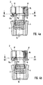
- the spindle 1 of a textile machine is inserted with its upper end region into the cavity of an upper coil adapter 2 with a hollow cylindrical basic shape.
- the upper adapter 2 consists essentially of two coherent axially displaceable parts, namely the upper locking part 3 and the lower coil driving part 4, which in the example is designed as a hollow cylindrical sleeve with a conical outer wall 5 in the upper end region. This is in frictional engagement with the opposite inner wall of a yarn spool 6.
- the relationship between the parts 3 and 4 mentioned is realized by a mutual hooking 43 .
- the locking or latching of the upper adapter 2 with the spindle 1 serves as a latching means, a cross slide 8 which, according to FIG. 2, can be displaced in a transverse guide 9 perpendicular to the adapter cylinder axis 10.
- the slide 8 has an annular tab 11 with a central bore 12, which surrounds the spindle 1.
- the bore 12 has a larger diameter than the spindle 1.
- the latter is provided in its area assigned to the adapter 2 with an annular groove 13, into which, according to FIG. 1, the tab 11 is engaged with a part 11a of the inner circumference delimiting the bore 12 is.
- the inclined surface 15 causes centering, in particular, of the slide 8 with its bore 12 in such a way that it can snap into the annular groove 13 of the spindle 1 in connection with the transverse pressure of the transverse spring 14.
- the asymmetrical mass distributions are due in particular to the specific design of the cross slide 8 and the asymmetrical arrangement of the cross spring 14.
- the stop and / or fixing pins 17 can perform the function of balancing bodies.
- the correct plug-on position can be achieved by manual pressure on the outside of the slide 8, as a result of which it is displaced against the radially outward force of the transverse spring 14.
- the slider 8 is brought radially inward into a release position by slight manual pressure, in which the surface of the central bore 12 completely covers the cross section of the spindle 1 or the tab 11 no longer covers the annular groove or the spindle 1 touched.
- the axial compression spring 7 can then move the locking part 3 axially upwards relative to the driving part 4 in order to complete the unlocking or disengagement of the slide 8.
- a lower coil adapter 18 is also arranged with a conical outer wall 5 at the lower end of the coil 6.
- the fixing and stop pin 17 has at its lower, front end a projecting stop pin 17a which plunges into an elongated hole 11b which is formed between the outer edge and the bore 12 of the ring plate.
- the longitudinal direction of the elongated hole 11b extends approximately radially with respect to the bore 12 and / or the spindle axis 10.
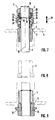
- the embodiment according to FIG. 6 serves to be able to take up 1 bobbin 6a, 6b of different lengths on a single spindle.
- the spindle 1 is provided at an axial distance from one another with two annular grooves 13a and 13b as detent devices.
- the upper annular groove 13b is used for the axial locking of the longer bobbin 6b, the lower annular groove 13a for locking the shorter bobbin 6a.
- latching means which are realized as spherical elements 19 in a ring-like or ring-like arrangement with a uniform distribution around the cylinder axis 10.
- the ball elements 19 are held in the unlocked or disengaged state, for example, in respective associated guide pockets 20 of a corresponding, ring-like arrangement and guided axially parallel to the annular groove 13 of the spindle 1 immediately before engagement.
- a locking ring 21 is pushed upward against the pressure of one or more axial or axially parallel locking springs 22.
- the spherical elements 19 are no longer the parallel section 23 of the inner ring of the circlip (parallel to the cylinder axis 10), but instead the polygonal subsequent inclined section 24 of the retaining ring inner wall is juxtaposed.
- the opposite inclined section 24 enables the ball elements 19 to step outward in the radial direction, so that they can hit the ring-like support shoulder 25 downward due to the action of gravity and the resulting play.
- This lies flush or at the same height as the lower edge of the annular groove 13, which is arranged similar to that of FIG. 1.
- the locking ring 21 which has been manually shifted upward, is released and moved downward due to the force of gravity and the pressure of the locking spring 22.
- the inner wall parallel section of the securing ring 21 comes into contact with the ball elements 19, as a result of which they are inserted into the annular groove 13. A radial and thus also axial movement of the ball elements 19 is prevented.
- the lower coil holder 18 is releasably attached to the spindle shaft by screwing means 26.
- These positive connection elements can transmit the force to the holder in a simple manner. If the friction surface of the coil driving part 4 wears, it can simply be replaced after loosening the screwing means 26, as illustrated in FIG. 5.
- the receptacle is firmly attached by gluing or pressing (see FIG. 3), it is preferably made of two parts. In the event of wear, the core remains on the shaft while an outer ring is replaced.
- the latching means are designed as spring hooks 27 arranged around the spindle 1 in the manner of a ring. Its upper shaft part 28 is on the inner wall of the locking part attached. By means of this articulation, the free hook part can snap or snap into the notch 30 of the spindle 1 when the adapter 2 or 2a is given a sufficient plug-on movement 29. This widens increasingly from the top edge 31 towards the center of the spindle, so that the top edge 31 forms a barb for the free hook end of the spring hook 27.
- a release ring 32 which is guided between the spindle 1 and the inner wall of the adapter 2 or 2a, is displaced downward in the direction of the notch 30.
- the spring hooks 27 expand radially outward with increasing displacement according to the plug-on movement 29, so that their free hook ends come out of engagement with the upper edge 31 or the barb of the notch 30. In this state, an upward pulling movement opposite to the pushing-on movement 29 downward is possible in order to carry out an exchange of the yarn package 6.
- the axial compression spring 7 is structurally integrated in the locking part 3 of the bobbin adapter 2 and generates the axial force necessary for frictional engagement between the conical outer wall 5 and the inside of the yarn bobbin 6.
- an axial compression spring 7a with a similar function for bringing about the frictional engagement between conical outer walls 5 and inner walls of the yarn bobbins 6 is arranged in the lower adapter 18a. Then an axial compression spring can be omitted in the upper coil adapter 2a, but need not.
Landscapes
- Spinning Or Twisting Of Yarns (AREA)
- Replacing, Conveying, And Pick-Finding For Filamentary Materials (AREA)
- Harvester Elements (AREA)
- Magnetic Resonance Imaging Apparatus (AREA)
- Control Of Motors That Do Not Use Commutators (AREA)
- General Induction Heating (AREA)
- Winding Filamentary Materials (AREA)
- Spinning Methods And Devices For Manufacturing Artificial Fibers (AREA)
Applications Claiming Priority (2)
| Application Number | Priority Date | Filing Date | Title |
|---|---|---|---|
| DE19530140 | 1995-08-16 | ||
| DE19530140 | 1995-08-16 |
Publications (3)
| Publication Number | Publication Date |
|---|---|
| EP0712802A2 true EP0712802A2 (fr) | 1996-05-22 |
| EP0712802A3 EP0712802A3 (fr) | 1997-01-08 |
| EP0712802B1 EP0712802B1 (fr) | 2000-03-22 |
Family
ID=7769628
Family Applications (1)
| Application Number | Title | Priority Date | Filing Date |
|---|---|---|---|
| EP96100312A Expired - Lifetime EP0712802B1 (fr) | 1995-08-16 | 1996-01-11 | Adaptateur de bobine |
Country Status (6)
| Country | Link |
|---|---|
| US (1) | US5718108A (fr) |
| EP (1) | EP0712802B1 (fr) |
| JP (1) | JPH0952659A (fr) |
| CN (1) | CN1143128A (fr) |
| AT (1) | ATE190964T1 (fr) |
| DE (2) | DE59604715D1 (fr) |
Cited By (1)
| Publication number | Priority date | Publication date | Assignee | Title |
|---|---|---|---|---|
| EP1982943A3 (fr) * | 2007-04-20 | 2009-11-04 | Oerlikon Textile GmbH & Co. KG | Dispositif de bobinage pour un poste de travail d'une machine textile fabriquant des bobines |
Families Citing this family (18)
| Publication number | Priority date | Publication date | Assignee | Title |
|---|---|---|---|---|
| DE10154654B4 (de) * | 2001-10-31 | 2010-11-25 | Novibra Gmbh | Spindeloberteil einer Spinn- oder Zwirnspindel und Spulenhülse zur Verwendung mit dem Spindeloberteil |
| DE10248929A1 (de) * | 2002-10-15 | 2004-04-29 | Wilhelm Stahlecker Gmbh | Spulenhülsenkupplung an Spinn- oder Zwirnspindeln |
| US7140573B1 (en) * | 2003-01-10 | 2006-11-28 | Helen Of Troy Limited | Rotating article dispenser |
| DE102004031253A1 (de) * | 2004-06-29 | 2006-01-19 | Texparts Gmbh | Hülsenkupplung |
| US7401749B2 (en) * | 2005-02-09 | 2008-07-22 | Simplehuman Llc | Holder for paper towel rolls with a quick-release retractable handle |
| US7530525B2 (en) * | 2005-03-29 | 2009-05-12 | Simplehuman Llc | Holder for paper towel rolls |
| ITFI20070134A1 (it) * | 2007-06-15 | 2008-12-16 | Mariella Crotti | "fuso per l'avvolgimento di filati su tubi o anime tubolari di avvolgimen- to" |
| DE102008060803A1 (de) * | 2008-12-01 | 2010-06-02 | C. & E. Fein Gmbh | Spule für eine Wickeleinrichtung |
| CN102616612A (zh) * | 2012-03-31 | 2012-08-01 | 镇江耐丝新型材料有限公司 | 一种不同直径工字轮转换装置 |
| CN102976167A (zh) * | 2012-12-03 | 2013-03-20 | 吴江市东飞化纤有限公司 | 组合式纱管 |
| CN104131372A (zh) * | 2014-08-08 | 2014-11-05 | 湖州市菱湖石淙永盛丝织厂 | 一种可吸震的锭子 |
| CN104131373A (zh) * | 2014-08-08 | 2014-11-05 | 湖州市菱湖石淙永盛丝织厂 | 一种带有减震装置的锭子 |
| US10889460B2 (en) * | 2016-11-03 | 2021-01-12 | Eric Martin Ferguson | Material handling device |
| CN106429623A (zh) * | 2016-12-02 | 2017-02-22 | 张家港特恩驰电缆有限公司 | 一种气缸式顶轴装置 |
| CN106757579B (zh) * | 2016-12-23 | 2018-11-20 | 晋中经纬恒腾纺机有限公司 | 纱管锭子连接器 |
| CN109320055A (zh) * | 2018-11-22 | 2019-02-12 | 重庆家喜陶瓷制品有限公司合川分公司 | 一种泡菜坛制造用冲头冷却器 |
| CN113697587B (zh) * | 2021-09-17 | 2023-04-18 | 绍兴中煜化纤股份有限公司 | 一种纺织机用纱线架 |
| CN114086295B (zh) * | 2021-11-18 | 2023-12-15 | 雁峰集团有限公司 | 一种圆织机用梭子及圆织机 |
Citations (8)
| Publication number | Priority date | Publication date | Assignee | Title |
|---|---|---|---|---|
| US1898115A (en) * | 1929-12-26 | 1933-02-21 | Whitin Machine Works | Retaining device for twister spindles |
| US1898131A (en) * | 1931-02-16 | 1933-02-21 | Whitin Machine Works | Locking device for bobbin caps |
| US2577571A (en) * | 1949-09-22 | 1951-12-04 | Du Pont | Apparatus for yarn twisting |
| DE1666078U (de) * | 1953-08-25 | 1953-10-29 | Debomit G M B H | Spulenhalter. |
| DE2261559A1 (de) * | 1972-12-15 | 1974-06-20 | Windmoeller & Hoelscher | Tragwelle fuer auf huelsen aufgewickeltes gut |
| DE7409733U (de) * | 1974-03-20 | 1975-09-11 | Kugelfischer G Schaefer & Co | Halte- und Zentriervorrichtung für Spulen von Textilmaschinen |
| DE3132159A1 (de) * | 1981-08-14 | 1983-03-03 | FAG Kugelfischer Georg Schäfer & Co, 8720 Schweinfurt | Spulensicherung |
| DE9016205U1 (fr) * | 1990-11-29 | 1991-02-14 | Fag Kugelfischer Georg Schaefer Kgaa, 8720 Schweinfurt, De |
Family Cites Families (8)
| Publication number | Priority date | Publication date | Assignee | Title |
|---|---|---|---|---|
| DE808133C (de) * | 1949-04-07 | 1951-07-12 | Hackethal Draht Und Kabel Werk | Papierspinner, insbesondere zum Auflegen von Papierbaendern auf elektrische Leiter |
| US3596846A (en) * | 1969-03-03 | 1971-08-03 | Stromberg Datagraphix Inc | Retaining device |
| US3731502A (en) * | 1972-02-24 | 1973-05-08 | Macon Machine Co | Releasable locking assembly |
| US4423609A (en) * | 1981-12-04 | 1984-01-03 | Osaka Bobbin Kabushiki Kaisha | Single-operation type of fastening device for bobbin spacer |
| US4720986A (en) * | 1984-06-12 | 1988-01-26 | Maschinenfabrik Scharer Ag | Spool mounting apparatus and method of using the same |
| IT1183624B (it) * | 1985-05-14 | 1987-10-22 | Carlo Menegatto | Dispositivo centrifugo di bloccaggio delle bobine |
| US4762179A (en) * | 1986-08-04 | 1988-08-09 | Halliburton Company | Pressure assist detonating bar and method for a tubing conveyed perforator |
| US5477709A (en) * | 1994-02-28 | 1995-12-26 | Mid-Atlantic Tool & Die, Inc. | Locking assembly for securing and sealing spools to a spindle during a dyeing operation |
-
1996
- 1996-01-11 EP EP96100312A patent/EP0712802B1/fr not_active Expired - Lifetime
- 1996-01-11 AT AT96100312T patent/ATE190964T1/de not_active IP Right Cessation
- 1996-01-11 DE DE59604715T patent/DE59604715D1/de not_active Expired - Fee Related
- 1996-01-12 US US08/586,006 patent/US5718108A/en not_active Expired - Fee Related
- 1996-01-17 DE DE29600744U patent/DE29600744U1/de not_active Expired - Lifetime
- 1996-02-13 CN CN96101263A patent/CN1143128A/zh active Pending
- 1996-03-27 JP JP8071847A patent/JPH0952659A/ja active Pending
Patent Citations (8)
| Publication number | Priority date | Publication date | Assignee | Title |
|---|---|---|---|---|
| US1898115A (en) * | 1929-12-26 | 1933-02-21 | Whitin Machine Works | Retaining device for twister spindles |
| US1898131A (en) * | 1931-02-16 | 1933-02-21 | Whitin Machine Works | Locking device for bobbin caps |
| US2577571A (en) * | 1949-09-22 | 1951-12-04 | Du Pont | Apparatus for yarn twisting |
| DE1666078U (de) * | 1953-08-25 | 1953-10-29 | Debomit G M B H | Spulenhalter. |
| DE2261559A1 (de) * | 1972-12-15 | 1974-06-20 | Windmoeller & Hoelscher | Tragwelle fuer auf huelsen aufgewickeltes gut |
| DE7409733U (de) * | 1974-03-20 | 1975-09-11 | Kugelfischer G Schaefer & Co | Halte- und Zentriervorrichtung für Spulen von Textilmaschinen |
| DE3132159A1 (de) * | 1981-08-14 | 1983-03-03 | FAG Kugelfischer Georg Schäfer & Co, 8720 Schweinfurt | Spulensicherung |
| DE9016205U1 (fr) * | 1990-11-29 | 1991-02-14 | Fag Kugelfischer Georg Schaefer Kgaa, 8720 Schweinfurt, De |
Cited By (1)
| Publication number | Priority date | Publication date | Assignee | Title |
|---|---|---|---|---|
| EP1982943A3 (fr) * | 2007-04-20 | 2009-11-04 | Oerlikon Textile GmbH & Co. KG | Dispositif de bobinage pour un poste de travail d'une machine textile fabriquant des bobines |
Also Published As
| Publication number | Publication date |
|---|---|
| ATE190964T1 (de) | 2000-04-15 |
| DE29600744U1 (de) | 1996-05-09 |
| US5718108A (en) | 1998-02-17 |
| DE59604715D1 (de) | 2000-04-27 |
| CN1143128A (zh) | 1997-02-19 |
| EP0712802B1 (fr) | 2000-03-22 |
| JPH0952659A (ja) | 1997-02-25 |
| EP0712802A3 (fr) | 1997-01-08 |
Similar Documents
| Publication | Publication Date | Title |
|---|---|---|
| EP0712802A2 (fr) | Support pour bobines de fil textile tournant à grande vitesse dans les machines textile ainsi que l'adaptateur de bobine associé | |
| EP0500489B1 (fr) | Outil et porte-outil pour machine à main | |
| AT393788B (de) | Zahnaerztliches handstueck mit abnehmbarer handstueckhuelse | |
| DE10031027A1 (de) | Spindel in einer Werkzeugmaschine | |
| EP1709931B1 (fr) | Organe moteur, en particulier pièce à main dentaire avec un accouplement détachable pour un porte-outil | |
| DE3814550C1 (en) | Clamping device for clamping two machine parts releasable from one another | |
| DE3835879C1 (fr) | ||
| DE3632045C1 (de) | Vorrichtung zur Verbindung zweier Werkzeugteile | |
| EP0789986B1 (fr) | Bielle de relevage pour accouplement à trois points de tracteur | |
| DE2620050C2 (fr) | ||
| DE19636594A1 (de) | Löseeinheit | |
| EP0428856B1 (fr) | Bielle de relevage pour tracteur | |
| DE3839681C2 (fr) | ||
| EP1279363B1 (fr) | Appareil pour la fixation d'un élément de brosses au chassis d'une machine pour nettoyer les sols | |
| DE19918638C2 (de) | Anschlußstück für einen Bohrer zum Erzeugen von Bohrungen in Knochengewebe, Bohrer und Bohrgerät | |
| EP0350786B1 (fr) | Dispositif de bobinage | |
| CH681504A5 (fr) | ||
| EP3515372B1 (fr) | Dispositif d'accouplement de prothèse conçu pour une prothèse, et prothèse équipée de ce dispositif d'accouplement de prothèse | |
| EP1140431A1 (fr) | Mandrin de serrage destine a des composants d'outil | |
| EP1273686B1 (fr) | Cylindre peigneur | |
| EP0776775B1 (fr) | Palier de roue | |
| EP0734815A1 (fr) | Outils pour Ôter des paliers | |
| DE3318745C2 (de) | Hobelmaschine, insbesondere Handhobel | |
| EP3165638A1 (fr) | Spindelschaft, spinnhülse und formwerkzeug | |
| EP0592866A1 (fr) | Tube de sortie de fil avec un support |
Legal Events
| Date | Code | Title | Description |
|---|---|---|---|
| PUAI | Public reference made under article 153(3) epc to a published international application that has entered the european phase |
Free format text: ORIGINAL CODE: 0009012 |
|
| AK | Designated contracting states |
Kind code of ref document: A2 Designated state(s): AT CH DE ES FR GB IT LI |
|
| PUAL | Search report despatched |
Free format text: ORIGINAL CODE: 0009013 |
|
| AK | Designated contracting states |
Kind code of ref document: A3 Designated state(s): AT CH DE ES FR GB IT LI |
|
| 17P | Request for examination filed |
Effective date: 19970708 |
|
| 17Q | First examination report despatched |
Effective date: 19980729 |
|
| GRAG | Despatch of communication of intention to grant |
Free format text: ORIGINAL CODE: EPIDOS AGRA |
|
| GRAG | Despatch of communication of intention to grant |
Free format text: ORIGINAL CODE: EPIDOS AGRA |
|
| GRAH | Despatch of communication of intention to grant a patent |
Free format text: ORIGINAL CODE: EPIDOS IGRA |
|
| GRAH | Despatch of communication of intention to grant a patent |
Free format text: ORIGINAL CODE: EPIDOS IGRA |
|
| RAP1 | Party data changed (applicant data changed or rights of an application transferred) |
Owner name: TEMCO TEXTILMASCHINENKOMPONENTEN GMBH |
|
| GRAA | (expected) grant |
Free format text: ORIGINAL CODE: 0009210 |
|
| AK | Designated contracting states |
Kind code of ref document: B1 Designated state(s): AT CH DE ES FR GB IT LI |
|
| PG25 | Lapsed in a contracting state [announced via postgrant information from national office to epo] |
Ref country code: ES Free format text: THE PATENT HAS BEEN ANNULLED BY A DECISION OF A NATIONAL AUTHORITY Effective date: 20000322 |
|
| REF | Corresponds to: |
Ref document number: 190964 Country of ref document: AT Date of ref document: 20000415 Kind code of ref document: T |
|
| REG | Reference to a national code |
Ref country code: CH Ref legal event code: EP |
|
| REF | Corresponds to: |
Ref document number: 59604715 Country of ref document: DE Date of ref document: 20000427 |
|
| REG | Reference to a national code |
Ref country code: CH Ref legal event code: NV Representative=s name: ISLER & PEDRAZZINI AG |
|
| GBT | Gb: translation of ep patent filed (gb section 77(6)(a)/1977) |
Effective date: 20000525 |
|
| ITF | It: translation for a ep patent filed |
Owner name: SOCIETA' ITALIANA BREVETTI S.P.A. |
|
| ET | Fr: translation filed | ||
| PG25 | Lapsed in a contracting state [announced via postgrant information from national office to epo] |
Ref country code: AT Free format text: LAPSE BECAUSE OF NON-PAYMENT OF DUE FEES Effective date: 20010111 |
|
| PGFP | Annual fee paid to national office [announced via postgrant information from national office to epo] |
Ref country code: GB Payment date: 20010119 Year of fee payment: 6 |
|
| PLBE | No opposition filed within time limit |
Free format text: ORIGINAL CODE: 0009261 |
|
| STAA | Information on the status of an ep patent application or granted ep patent |
Free format text: STATUS: NO OPPOSITION FILED WITHIN TIME LIMIT |
|
| PGFP | Annual fee paid to national office [announced via postgrant information from national office to epo] |
Ref country code: FR Payment date: 20010125 Year of fee payment: 6 Ref country code: CH Payment date: 20010125 Year of fee payment: 6 |
|
| 26N | No opposition filed | ||
| REG | Reference to a national code |
Ref country code: GB Ref legal event code: IF02 |
|
| PG25 | Lapsed in a contracting state [announced via postgrant information from national office to epo] |
Ref country code: GB Free format text: LAPSE BECAUSE OF NON-PAYMENT OF DUE FEES Effective date: 20020111 |
|
| PG25 | Lapsed in a contracting state [announced via postgrant information from national office to epo] |
Ref country code: LI Free format text: LAPSE BECAUSE OF NON-PAYMENT OF DUE FEES Effective date: 20020131 Ref country code: CH Free format text: LAPSE BECAUSE OF NON-PAYMENT OF DUE FEES Effective date: 20020131 |
|
| GBPC | Gb: european patent ceased through non-payment of renewal fee |
Effective date: 20020111 |
|
| REG | Reference to a national code |
Ref country code: CH Ref legal event code: PL |
|
| PG25 | Lapsed in a contracting state [announced via postgrant information from national office to epo] |
Ref country code: FR Free format text: LAPSE BECAUSE OF NON-PAYMENT OF DUE FEES Effective date: 20020930 |
|
| REG | Reference to a national code |
Ref country code: FR Ref legal event code: ST |
|
| PGFP | Annual fee paid to national office [announced via postgrant information from national office to epo] |
Ref country code: DE Payment date: 20040317 Year of fee payment: 9 |
|
| PG25 | Lapsed in a contracting state [announced via postgrant information from national office to epo] |
Ref country code: IT Free format text: LAPSE BECAUSE OF NON-PAYMENT OF DUE FEES;WARNING: LAPSES OF ITALIAN PATENTS WITH EFFECTIVE DATE BEFORE 2007 MAY HAVE OCCURRED AT ANY TIME BEFORE 2007. THE CORRECT EFFECTIVE DATE MAY BE DIFFERENT FROM THE ONE RECORDED. Effective date: 20050111 |
|
| PG25 | Lapsed in a contracting state [announced via postgrant information from national office to epo] |
Ref country code: DE Free format text: LAPSE BECAUSE OF NON-PAYMENT OF DUE FEES Effective date: 20050802 |