EP0428856B1 - Bielle de relevage pour tracteur - Google Patents
Bielle de relevage pour tracteur Download PDFInfo
- Publication number
- EP0428856B1 EP0428856B1 EP90119379A EP90119379A EP0428856B1 EP 0428856 B1 EP0428856 B1 EP 0428856B1 EP 90119379 A EP90119379 A EP 90119379A EP 90119379 A EP90119379 A EP 90119379A EP 0428856 B1 EP0428856 B1 EP 0428856B1
- Authority
- EP
- European Patent Office
- Prior art keywords
- sleeve
- threaded
- adjusting sleeve
- lifting rod
- teeth
- Prior art date
- Legal status (The legal status is an assumption and is not a legal conclusion. Google has not performed a legal analysis and makes no representation as to the accuracy of the status listed.)
- Expired - Lifetime
Links
- 238000007789 sealing Methods 0.000 description 3
- 238000006073 displacement reaction Methods 0.000 description 2
- 230000002349 favourable effect Effects 0.000 description 2
- 239000000314 lubricant Substances 0.000 description 1
- 230000001050 lubricating effect Effects 0.000 description 1
- 210000002445 nipple Anatomy 0.000 description 1
Images


Classifications
-
- A—HUMAN NECESSITIES
- A01—AGRICULTURE; FORESTRY; ANIMAL HUSBANDRY; HUNTING; TRAPPING; FISHING
- A01B—SOIL WORKING IN AGRICULTURE OR FORESTRY; PARTS, DETAILS, OR ACCESSORIES OF AGRICULTURAL MACHINES OR IMPLEMENTS, IN GENERAL
- A01B59/00—Devices specially adapted for connection between animals or tractors and agricultural machines or implements
- A01B59/002—Details, component parts
- A01B59/004—Length-adjustable links
-
- Y—GENERAL TAGGING OF NEW TECHNOLOGICAL DEVELOPMENTS; GENERAL TAGGING OF CROSS-SECTIONAL TECHNOLOGIES SPANNING OVER SEVERAL SECTIONS OF THE IPC; TECHNICAL SUBJECTS COVERED BY FORMER USPC CROSS-REFERENCE ART COLLECTIONS [XRACs] AND DIGESTS
- Y10—TECHNICAL SUBJECTS COVERED BY FORMER USPC
- Y10T—TECHNICAL SUBJECTS COVERED BY FORMER US CLASSIFICATION
- Y10T403/00—Joints and connections
- Y10T403/29—Rotarily connected, differentially translatable members, e.g., turn-buckle, etc.
- Y10T403/295—Rotarily connected, differentially translatable members, e.g., turn-buckle, etc. having locking means
-
- Y—GENERAL TAGGING OF NEW TECHNOLOGICAL DEVELOPMENTS; GENERAL TAGGING OF CROSS-SECTIONAL TECHNOLOGIES SPANNING OVER SEVERAL SECTIONS OF THE IPC; TECHNICAL SUBJECTS COVERED BY FORMER USPC CROSS-REFERENCE ART COLLECTIONS [XRACs] AND DIGESTS
- Y10—TECHNICAL SUBJECTS COVERED BY FORMER USPC
- Y10T—TECHNICAL SUBJECTS COVERED BY FORMER US CLASSIFICATION
- Y10T403/00—Joints and connections
- Y10T403/60—Biased catch or latch
- Y10T403/602—Biased catch or latch by separate spring
-
- Y—GENERAL TAGGING OF NEW TECHNOLOGICAL DEVELOPMENTS; GENERAL TAGGING OF CROSS-SECTIONAL TECHNOLOGIES SPANNING OVER SEVERAL SECTIONS OF THE IPC; TECHNICAL SUBJECTS COVERED BY FORMER USPC CROSS-REFERENCE ART COLLECTIONS [XRACs] AND DIGESTS
- Y10—TECHNICAL SUBJECTS COVERED BY FORMER USPC
- Y10T—TECHNICAL SUBJECTS COVERED BY FORMER US CLASSIFICATION
- Y10T74/00—Machine element or mechanism
- Y10T74/21—Elements
- Y10T74/2142—Pitmans and connecting rods
- Y10T74/2151—Longitudinally adjustable
Definitions
- the invention relates to a variable-length lifting strut for a linkage which can be raised and lowered via a power drive of the attachment device of a tractor, the first connection end of which is intended for attachment to the power arm of the power drive and the second connection end of which is intended for attachment to the lower link, each of which has opposite threads from corresponding threaded sections Adjustment sleeve are received, wherein at one end of the adjustment sleeve the threaded portion is an internal thread portion into which the associated connection end is screwed with a threaded pin and wherein the adjustment sleeve is rotatable via a handle
- a variable-length strut with the aforementioned features is known from FR-A-1148609.
- the handle is firmly connected to the adjustment sleeve.
- the two connection ends can be adjusted in the event of unintentional adjustment of the adjustment sleeve in the sense of a change in length.
- a three-point hitch with a lifting strut is also known from US Pat. No. 3,056,458, in which the lifting strut is designed to be telescopic. In addition to the ability to be telescoped, a thread setting is provided. The free telescopability can be canceled. For securing purposes, plug connections are provided which fix the two connection ends to one another in certain locking positions.
- the invention has for its object to provide a lifting strut that has the shortest possible overall length with respect to the mutually adjustable members and in which the actuation is also improved and furthermore a locking is achieved when the required length is achieved without special fixing means.
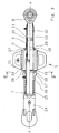
- the adjusting sleeve is provided at the other end with an externally threaded section, that a connection end has an internally threaded threaded sleeve which is screwed onto the externally threaded section of the adjusting sleeve, and that the handle is part of a handle sleeve which is on the adjusting sleeve is arranged displaceably in the axial direction of the lifting strut and can optionally be converted into a non-rotatable connection with the adjusting sleeve or into a common non-rotating connection with the adjusting sleeve and the threaded sleeve.
- the adjustable grip sleeve can twist the adjustment sleeve and thus change the length of the lifting strut. Due to the independent mobility of the grip sleeve, the most favorable grip position for the operator can be achieved depending on the requirements. This can be achieved by engaging the groove of the grip sleeve with the teeth of the adjustment sleeve. In addition, a locking can also be ensured by sliding the grip sleeve over the teeth of both the adjusting sleeve and the threaded sleeve, so that the rotational position of the threaded sleeve relative to the adjusting sleeve can't change anymore. This defines the length of the lifting strut.
- Another advantage is that the grip sleeve in the locking position covers the external thread section of the adjusting sleeve and thus protects against damage.
- the proposed locking possibility is achieved by the special arrangement of the threaded sections of the adjusting sleeve.
- the combination of the external thread section and the internal thread section gives the advantage that the shortest possible length or greatest possible displacement is achieved.
- the entire length of the adjustment sleeve is available for immersing the threaded pin of the other connection end.
- the lifting strut is generally mounted in such a way that the connection end having the threaded sleeve is assigned to the lower link, while the other connection end is assigned to a power arm of the power drive.
- the adjusting sleeve and the threaded sleeve are each provided with at least one tooth projecting radially from their outer surfaces and that the grip sleeve has at least one axially extending groove adapted to the teeth in its bore, with which it bears over the Teeth of the threaded sleeve and / or adjusting sleeve can be pushed.
- the teeth or grooves are therefore provided as means for the rotationally fixed connection between the threaded sleeve and / or the adjusting sleeve.
- the grip sleeve on its end face facing the threaded sleeve with at least one stop which is circumferentially offset and protrudes from the groove and which rotates with the teeth assigned to the adjustment sleeve Plant can be brought.
- the threaded sleeve and the adjusting sleeve are preferably provided with two diametrically opposed teeth and the handle sleeve with four grooves offset at right angles to one another.
- teeth of the adjustment sleeve can be formed directly, it is expedient to assign them to a disk-like twisting star which is connected to the adjustment sleeve.
- the grip sleeve is provided with a stop collar on its end face facing away from the threaded sleeve. Due to the approximately vertical arrangement of the lifting strut, the stop collar ensures that the grip sleeve is held in the correct position with respect to the adjusting sleeve and the threaded sleeve.
- a stop is provided between two grooves.
- a total of four stops and four grooves are provided, so that there is a significant increase in the attack positions.
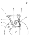
- the tractor 1 shown in Figure 1 has a three-point hitch at its rear.
- the three-point hitch comprises the two lower links 2, of which only one can be seen, however, since the second is arranged at a distance from the first in the plane of the drawing.
- the two lower links 2 are offset laterally to the longitudinal axis of the tractor 1.
- the lower links 2 can be raised and lowered via a power drive of the tractor 1, not shown.
- two force arms 4 are provided, to each of which a lower link 2 is connected via the lifting strut 3.
- the upper connection end 9 is designed, for example, as a ball joint, while the lower connection end 14 is assigned to the lower link 2 and engages over the lower link in a fork-like manner.
- the lifting strut 3 is connected in an articulated manner to the lower link 2 and the associated power arm 4 via a bolt connection.
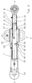
- a lifting strut 3 is described in detail with reference to the drawing figures 2 to 9.
- the lifting strut 3 has a tubular adjusting sleeve 6, which is provided on one end with an external thread section 7 and on the other end with an internal thread section 8.
- the internal thread section 8 is assigned the connecting end 9 with a ball joint.
- a threaded pin 10 is connected to the ball joint of the connection end 9 and is screwed into the internal thread section 8 in the bore of the adjusting sleeve 6.
- the pitch of the two threaded sections 7, 8 of the adjusting sleeve 6 run in opposite directions.
- the threaded portion of the threaded pin is designated 11.
- the cylindrical section 12 adjoins this towards the ball joint.
- the adjusting sleeve 6 is assigned a sealing cap 13, which is located on the creates cylindrical section 12 of the connecting end 9 sealing.
- a lubricating nipple for supplying the two interlocking threads of the threaded pin 10 and the internal thread section 8 provided in the bore, for example, with lubricant can also be molded into this.
- the second connection end 14 of the lifting strut 3 is screwed onto the external thread section 7 of the adjusting sleeve 6.
- the second connection end 14 comprises a connecting fork which is to be connected to the lower link 2.
- the second connection end 14 comprises a threaded sleeve 15, the bore of which is provided with an internal thread 16.
- the threaded sleeve 15 is screwed onto the external thread section 7 of the adjusting sleeve 6.
- Two diametrically opposite teeth 17 protrude radially from the outer surface of the threaded sleeve 15.
- a disk-shaped rotating star 18 is fixedly attached to the outer circumference of the adjusting sleeve 6.
- the twisting star 18 has two pairs of teeth 19 corresponding to the teeth 17 of the threaded sleeve 15. This increases the number of possible locking positions. Only one pair is required.
- the two teeth 17 and 19 have the same cross-sectional shape.
- a grip sleeve 21 is also slidably arranged on the outer surface 20 of the adjusting sleeve 6, a grip sleeve 21 is also slidably arranged.
- Two diametrically opposite handles 22 protrude radially from the outer surface of the grip sleeve 21, as can be seen in particular from the drawing figures 7 to 9. These are used for manual intervention for the rotation of the adjusting sleeve 6.
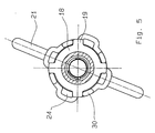
- the grip sleeve 21 also has a bore 23 in which four axially extending grooves 24 are distributed over the circumference. The grooves 24 and the diameter of the bore 23 are designed so that the grip sleeve 21 can be pushed over the twist star 18 with its teeth 19 and over the teeth 17 and the outer contour of the threaded sleeve 15.
- the grip sleeve 21 has on its end face 29 facing away from the threaded sleeve 15 a stop collar 25 projecting radially inwards into the contour of the bore 23.
- the stop collar 25 is also pierced.
- the bore is designated 26. It is adapted to the outer diameter of the adjusting sleeve 6 so that the handle sleeve 21 is easily displaceable on the adjusting sleeve 6.
- openings 27 are provided in the end face, which serve that no dirt can accumulate in the grooves 24 and this can be pushed out through the openings 27 when the handle sleeve 21 is moved via the teeth 19 through the openings.
- Stops 30 project axially from the end face 28 of the grip sleeve 21 facing the threaded sleeve 15.
- a total of four stops 30 are provided, which are arranged circumferentially offset to the grooves 24.
- a stop 30 is present in each case between two grooves 24 which follow one another in the circumferential direction.
- the grip sleeve 21 In the position shown in Figure 2, the grip sleeve 21 is in the free rotation position. In this position, the grip sleeve 21 can be freely rotated by hand on the adjustment sleeve 6. This serves to bring the grip sleeve 21 into the correct engagement position with respect to the twisting star 18 in order to make the lever arm as large as possible for rotating the adjustment sleeve 6 to change the length of the lifting strut 3 to achieve the opposite thread sections 7 and 8.
- all stops 30, as can be seen particularly in FIG. 5, can be brought into circumferential contact with the four teeth 19 of the rotating star 18 connected to the adjusting sleeve 6 (FIGS. 3 and 5).
- the grooves 24 of the grip sleeve 21 in order to establish a rotationally fixed connection to the teeth 19 of the twist star 18. If the correct length is reached, locking is possible in that after the teeth 19 of the rotating star 18 have been brought into an aligned position with the teeth 17 of the threaded sleeve 15, the grip sleeve 21 with the grooves 24 both over the teeth 19 of the rotating star 18 , as well as the teeth 17 of the threaded sleeve 15 is shifted. The displacement in the assembled state of the lifting strut 3 on the tractor 1 is carried out downward until the stop collar 25 of the grip sleeve 21 comes to rest on the rotating star 18.
Landscapes
- Life Sciences & Earth Sciences (AREA)
- Zoology (AREA)
- Engineering & Computer Science (AREA)
- Mechanical Engineering (AREA)
- Soil Sciences (AREA)
- Environmental Sciences (AREA)
- Lifting Devices For Agricultural Implements (AREA)
- Agricultural Machines (AREA)
Claims (9)
- Tirant de levage (3) à longueur variable pour un bras inférieur (2) qui se lève et s'abaisse par entraînement mécanique dans un dispositif d'attelage d'un tracteur (1), dont la première extrémité de raccordement (9) est conçue pour la fixation (4) sur le bras de force de l'entraînement mécanique et dont la seconde extrémité de raccordement (14) est conçue pour la fixation sur le bras inférieur (2), chacune des extrémités étant retenue par des filetages et taraudages opposés sur des segments correspondants (7, 8) d'une douille de réglage (6), le segment se trouvant sur une extrémité de la douille de réglage (6) étant un segment de taraudage (8) dans lequel est vissé l'extrémité de raccordement correspondante avec un tenon fileté (10), et la douille de réglage (6) pouvant être tournée par une poignée, caractérisé en ce que la douille de réglage (6) est pourvue sur l'autre extrémité d'un segment de filetage (7), en ce qu'une extrémité de raccordement (14) présente une douille (15) à taraudage (16) qui est vissée sur le segment de filetage (7) de la douille de réglage (6), et en ce que la poignée fait partie d'un manchon de poignée (21) qui est agencé à déplacement sur la douille de réglage (6) dans la direction axiale (x-x) du tirant de levage (3) et qui peut être déplacé au choix dans une liaison solidaire en rotation avec la douille de réglage (6) ou en liaison commune solidaire en rotation avec la douille de réglage (6) et la douille taraudée (15).
- Tirant de levage selon la revendication 1, caractérisé en ce que la douille de réglage (6) et la douille taraudée (15) sont chacune pourvues d'au moins une dent (17, 19) faisant saillie radialement depuis leur face extérieure et en ce que le manchon de poignée (21) présente dans son alésage au moins une gorge (24) adaptée aux dents (17, 19) et s'étendant axialement, gorge avec laquelle il peut être déplacé via les dents (17, 19) de la douille taraudée (15) et/ou de la douille de réglage (6).
- Tirant de levage selon la revendication 1, caractérisé en ce que le manchon de poignée (21) peut être déplacé dans une position de rotation libre hors d'engagement avec la douille de réglage (6) et la douille taraudée (15).
- Tirant de levage selon la revendication 2 et 3, caractérisé en ce que le manchon de poignée (21) est pourvu sur sa face (28) orientée vers la douille taraudée (15) d'au moins une butée (30) en saillie décalée circonférentiellement par rapport à la gorge (24), butée qui peut être amenée en position solidaire en rotation avec les dents (19) associées à la douille de réglage (6).
- Tirant de levage selon l'une des revendications 1, 2 ou 4, caractérisé en ce que la douille taraudée (15) et la douille de réglage (6) sont pourvues de deux dents (17, 19) diamétralement opposées et le manchon de poignée (21) est pourvu de quatre gorges (24) décalées à angles droits les unes par rapport aux autres.
- Tirant de levage selon l'une ou plusieurs des revendications 1 à 5, caractérisé en ce que les dents (19) de la douille de réglage (6) sont associées à une étoile de rotation (18) en forme de disque qui est reliée à la douille de réglage (6).
- Tirant de levage selon la revendication 2, caractérisé en ce que le manchon de poignée (21) est pourvu d'un bourrelet de butée (25) sur sa face (29) opposée à la douille taraudée (15).
- Tirant de levage selon la revendication 7, caractérisé en ce que le bourrelet de butée (25) est pourvu d'un percement (27) dans la région de chaque gorge.
- Tirant de levage selon les revendications 4 et 5, caractérisé en ce qu'une butée (30) est disposée respectivement entre deux gorges (24).
Priority Applications (1)
| Application Number | Priority Date | Filing Date | Title |
|---|---|---|---|
| AT90119379T ATE101475T1 (de) | 1989-11-18 | 1990-10-10 | Hubstrebe fuer einen traktor. |
Applications Claiming Priority (2)
| Application Number | Priority Date | Filing Date | Title |
|---|---|---|---|
| DE3938418 | 1989-11-18 | ||
| DE3938418A DE3938418C1 (fr) | 1989-11-18 | 1989-11-18 |
Publications (3)
| Publication Number | Publication Date |
|---|---|
| EP0428856A2 EP0428856A2 (fr) | 1991-05-29 |
| EP0428856A3 EP0428856A3 (en) | 1991-08-14 |
| EP0428856B1 true EP0428856B1 (fr) | 1994-02-16 |
Family
ID=6393818
Family Applications (1)
| Application Number | Title | Priority Date | Filing Date |
|---|---|---|---|
| EP90119379A Expired - Lifetime EP0428856B1 (fr) | 1989-11-18 | 1990-10-10 | Bielle de relevage pour tracteur |
Country Status (6)
| Country | Link |
|---|---|
| US (1) | US5042588A (fr) |
| EP (1) | EP0428856B1 (fr) |
| JP (1) | JPH088802B2 (fr) |
| AT (1) | ATE101475T1 (fr) |
| DE (1) | DE3938418C1 (fr) |
| RU (1) | RU1804277C (fr) |
Families Citing this family (11)
| Publication number | Priority date | Publication date | Assignee | Title |
|---|---|---|---|---|
| US5299469A (en) * | 1993-02-22 | 1994-04-05 | Amanda Bent Bolt Co. | Adjustable linkage assembly |
| DE19605560C1 (de) * | 1996-02-15 | 1997-08-14 | Walterscheid Gmbh Gkn | Hubstange für die Dreipunktanbaueinrichtung eines Traktors |
| US5702196A (en) * | 1996-06-21 | 1997-12-30 | Teleflex, Incorporated | Turnbuckle-type adjustable link |
| DE102004032312A1 (de) * | 2004-07-03 | 2006-01-19 | Deere & Company, Moline | Griff, Hubspindelanordnung und Fertigungsverfahren für einen Griff |
| US8721723B2 (en) | 2009-01-12 | 2014-05-13 | Globus Medical, Inc. | Expandable vertebral prosthesis |
| ITBO20090459A1 (it) * | 2009-07-16 | 2011-01-17 | Cbm Spa | Maniglia per tirante di attacco a tre punti |
| DE202011002815U1 (de) * | 2010-12-21 | 2012-01-24 | Hans Sauermann | Stabilisator für einen Unter- und/oder Oberlenker eines Ackerschleppers |
| DE102011052461A1 (de) | 2011-08-08 | 2013-02-14 | Gkn Walterscheid Gmbh | Längenveränderliche Hubstrebe |
| DE102012211931B4 (de) | 2012-07-09 | 2016-10-27 | Deere & Company | Hubspindel |
| GB201317493D0 (en) * | 2013-10-03 | 2013-11-20 | Agco Int Gmbh | Tractor counterweight mounting |
| EP3261426B1 (fr) * | 2015-02-24 | 2020-04-01 | AGCO Corporation | Ensemble lien de verrouillage pour attelage de machine de travail |
Family Cites Families (16)
| Publication number | Priority date | Publication date | Assignee | Title |
|---|---|---|---|---|
| FR1148609A (fr) * | 1956-03-02 | 1957-12-12 | Barre réglable perfectionnée | |
| DE1096102B (de) * | 1958-09-03 | 1960-12-29 | Traktorenwerk Schoenebeck Veb | Anbauvorrichtung, insbesondere fuer den Drei- bzw. Vierpunktanbau von landwirtschaftlichen Geraeten an Schlepper |
| US3056458A (en) * | 1959-06-03 | 1962-10-02 | Harold P Gray | Tractor hitch organization |
| US3255828A (en) * | 1963-01-25 | 1966-06-14 | Paul D Abbott | Three-point hitch linkage equalizer |
| GB1175371A (en) * | 1966-03-02 | 1969-12-23 | Massey Ferguson Perkins Ltd | Improvements in or relating to Tractor-Implement Hitches. |
| US3498638A (en) * | 1968-05-06 | 1970-03-03 | Deere & Co | Quick coupler |
| US3708017A (en) * | 1970-01-15 | 1973-01-02 | N Alexandrovsky | Arrangement for mounting agricultural implements on a tractor with rocking side transmissions |
| DE7212144U (de) * | 1972-03-30 | 1972-07-13 | Weiste H & Co Gmbh | Laengenveraenderlicher oberlenker fuer landwirtschaftliche geraete |
| DE2227179C2 (de) * | 1972-06-03 | 1974-02-07 | Heinrich Weiste & Co Gmbh, 4770 Soest | Längenveränderlicher Oberlenker |
| US3825283A (en) * | 1973-06-04 | 1974-07-23 | Allis Chalmers | Adjustable link with locking wrench for a tractor three-point hitch |
| AT341814B (de) * | 1975-09-24 | 1978-02-27 | Walterscheid Gmbh Jean | Langenveranderbarer oberlenker |
| US4034999A (en) * | 1976-02-12 | 1977-07-12 | Royal Industries, Inc. | Adjustable top link for 3-point hitch |
| US4519623A (en) * | 1983-05-09 | 1985-05-28 | Orthman Manufacturing, Inc. | Tractor front end hitch |
| DE3439048C2 (de) * | 1984-10-25 | 1986-09-11 | Deere & Co., Moline, Ill., US, Niederlassung Deere & Co. European Office, 6800 Mannheim | Kraftheber für ein Hubgerät |
| JPH01285106A (ja) * | 1988-05-10 | 1989-11-16 | Kubota Ltd | 作業車の作業装置ローリング構造 |
| JPH0671362B2 (ja) * | 1987-12-10 | 1994-09-14 | 株式会社クボタ | ターンバックル |
-
1989
- 1989-11-18 DE DE3938418A patent/DE3938418C1/de not_active Expired - Lifetime
-
1990
- 1990-10-10 AT AT90119379T patent/ATE101475T1/de not_active IP Right Cessation
- 1990-10-10 EP EP90119379A patent/EP0428856B1/fr not_active Expired - Lifetime
- 1990-11-13 US US07/612,615 patent/US5042588A/en not_active Expired - Fee Related
- 1990-11-13 RU SU904831533A patent/RU1804277C/ru active
- 1990-11-19 JP JP2311662A patent/JPH088802B2/ja not_active Expired - Fee Related
Also Published As
| Publication number | Publication date |
|---|---|
| JPH03172104A (ja) | 1991-07-25 |
| US5042588A (en) | 1991-08-27 |
| DE3938418C1 (fr) | 1991-03-21 |
| JPH088802B2 (ja) | 1996-01-31 |
| RU1804277C (ru) | 1993-03-23 |
| EP0428856A3 (en) | 1991-08-14 |
| EP0428856A2 (fr) | 1991-05-29 |
| ATE101475T1 (de) | 1994-03-15 |
Similar Documents
| Publication | Publication Date | Title |
|---|---|---|
| EP0710519B1 (fr) | Mandrin porte-foret | |
| DE2827948C3 (de) | Ausrückkupplung | |
| EP0413197B1 (fr) | Roulette à pivot pour plate-formes, échafaudages ou similaires | |
| EP0428856B1 (fr) | Bielle de relevage pour tracteur | |
| DE112004001285T5 (de) | Seil-Aktuator für Lenden-Stütze | |
| AT391969B (de) | Laengenveraenderliche seitenstrebe | |
| EP0512498B1 (fr) | Outil pour ôter un palier d'un axe | |
| EP0712802A2 (fr) | Support pour bobines de fil textile tournant à grande vitesse dans les machines textile ainsi que l'adaptateur de bobine associé | |
| EP0789986B1 (fr) | Bielle de relevage pour accouplement à trois points de tracteur | |
| DE19944749C2 (de) | Seitenstrebe für einen Unterlenker eines Traktors | |
| DE2803822A1 (de) | Dreiteilige auseinanderziehbare teleskopwelle zur uebertragung von drehmomenten | |
| DE2309298A1 (de) | Bohrvorrichtung | |
| AT413431B (de) | Schutzvorrichtung für eine antriebsordnung mit einem doppelkreuzgelenk | |
| DE4442533A1 (de) | Bohrvorrichtung | |
| DE3324494C1 (de) | Walzwerkzeug | |
| EP3784439B1 (fr) | Pince | |
| DE4228946C2 (de) | Spindelkopf für Werkzeugrevolver | |
| DE60209396T2 (de) | Kuppelgestell für landwirtschaftliche Maschine | |
| DE3219011C2 (fr) | ||
| DE102019121314A1 (de) | Betätigungsschlüssel für Armaturen | |
| DE2909469C2 (de) | Spannvorrichtung für chirurgische Werkzeuge | |
| DE102012211931B4 (de) | Hubspindel | |
| DE19746216A1 (de) | Kreiselrechen für eine Heuwerbungsmaschine | |
| DE3518661A1 (de) | Schraubenschluessel | |
| EP0103094B1 (fr) | Manchon d'accouplement pour la jonction à un outil de travail présentant un raccord à accouplement rapide |
Legal Events
| Date | Code | Title | Description |
|---|---|---|---|
| PUAI | Public reference made under article 153(3) epc to a published international application that has entered the european phase |
Free format text: ORIGINAL CODE: 0009012 |
|
| AK | Designated contracting states |
Kind code of ref document: A2 Designated state(s): AT DE FR GB IT |
|
| PUAL | Search report despatched |
Free format text: ORIGINAL CODE: 0009013 |
|
| AK | Designated contracting states |
Kind code of ref document: A3 Designated state(s): AT DE FR GB IT |
|
| 17P | Request for examination filed |
Effective date: 19910701 |
|
| 17Q | First examination report despatched |
Effective date: 19920908 |
|
| RAP1 | Party data changed (applicant data changed or rights of an application transferred) |
Owner name: GKN WALTERSCHEID GMBH |
|
| RBV | Designated contracting states (corrected) |
Designated state(s): AT FR GB IT |
|
| REG | Reference to a national code |
Ref country code: DE Ref legal event code: 8566 |
|
| GRAA | (expected) grant |
Free format text: ORIGINAL CODE: 0009210 |
|
| ITF | It: translation for a ep patent filed |
Owner name: DE DOMINICIS & MAYER S.R.L. |
|
| AK | Designated contracting states |
Kind code of ref document: B1 Designated state(s): AT FR GB IT |
|
| REF | Corresponds to: |
Ref document number: 101475 Country of ref document: AT Date of ref document: 19940315 Kind code of ref document: T |
|
| GBT | Gb: translation of ep patent filed (gb section 77(6)(a)/1977) |
Effective date: 19940223 |
|
| ET | Fr: translation filed | ||
| PLBE | No opposition filed within time limit |
Free format text: ORIGINAL CODE: 0009261 |
|
| STAA | Information on the status of an ep patent application or granted ep patent |
Free format text: STATUS: NO OPPOSITION FILED WITHIN TIME LIMIT |
|
| 26N | No opposition filed | ||
| REG | Reference to a national code |
Ref country code: GB Ref legal event code: IF02 |
|
| PGFP | Annual fee paid to national office [announced via postgrant information from national office to epo] |
Ref country code: GB Payment date: 20020918 Year of fee payment: 13 |
|
| PGFP | Annual fee paid to national office [announced via postgrant information from national office to epo] |
Ref country code: FR Payment date: 20021017 Year of fee payment: 13 |
|
| PGFP | Annual fee paid to national office [announced via postgrant information from national office to epo] |
Ref country code: AT Payment date: 20021022 Year of fee payment: 13 |
|
| PG25 | Lapsed in a contracting state [announced via postgrant information from national office to epo] |
Ref country code: GB Free format text: LAPSE BECAUSE OF NON-PAYMENT OF DUE FEES Effective date: 20031010 Ref country code: AT Free format text: LAPSE BECAUSE OF NON-PAYMENT OF DUE FEES Effective date: 20031010 |
|
| GBPC | Gb: european patent ceased through non-payment of renewal fee |
Effective date: 20031010 |
|
| PG25 | Lapsed in a contracting state [announced via postgrant information from national office to epo] |
Ref country code: FR Free format text: LAPSE BECAUSE OF NON-PAYMENT OF DUE FEES Effective date: 20040630 |
|
| REG | Reference to a national code |
Ref country code: FR Ref legal event code: ST |
|
| PG25 | Lapsed in a contracting state [announced via postgrant information from national office to epo] |
Ref country code: IT Free format text: LAPSE BECAUSE OF NON-PAYMENT OF DUE FEES;WARNING: LAPSES OF ITALIAN PATENTS WITH EFFECTIVE DATE BEFORE 2007 MAY HAVE OCCURRED AT ANY TIME BEFORE 2007. THE CORRECT EFFECTIVE DATE MAY BE DIFFERENT FROM THE ONE RECORDED. Effective date: 20051010 |