EP0712802A2 - Support for yarn bobbins rotating at high speed in textile machines and associated bobbin adapter - Google Patents
Support for yarn bobbins rotating at high speed in textile machines and associated bobbin adapter Download PDFInfo
- Publication number
- EP0712802A2 EP0712802A2 EP96100312A EP96100312A EP0712802A2 EP 0712802 A2 EP0712802 A2 EP 0712802A2 EP 96100312 A EP96100312 A EP 96100312A EP 96100312 A EP96100312 A EP 96100312A EP 0712802 A2 EP0712802 A2 EP 0712802A2
- Authority
- EP
- European Patent Office
- Prior art keywords
- spindle
- adapter
- base body
- latching means
- axially
- Prior art date
- Legal status (The legal status is an assumption and is not a legal conclusion. Google has not performed a legal analysis and makes no representation as to the accuracy of the status listed.)
- Granted
Links
Images


Classifications
-
- B—PERFORMING OPERATIONS; TRANSPORTING
- B65—CONVEYING; PACKING; STORING; HANDLING THIN OR FILAMENTARY MATERIAL
- B65H—HANDLING THIN OR FILAMENTARY MATERIAL, e.g. SHEETS, WEBS, CABLES
- B65H54/00—Winding, coiling, or depositing filamentary material
- B65H54/02—Winding and traversing material on to reels, bobbins, tubes, or like package cores or formers
- B65H54/40—Arrangements for rotating packages
- B65H54/54—Arrangements for supporting cores or formers at winding stations; Securing cores or formers to driving members
- B65H54/543—Securing cores or holders to supporting or driving members, e.g. collapsible mandrels
-
- B—PERFORMING OPERATIONS; TRANSPORTING
- B65—CONVEYING; PACKING; STORING; HANDLING THIN OR FILAMENTARY MATERIAL
- B65H—HANDLING THIN OR FILAMENTARY MATERIAL, e.g. SHEETS, WEBS, CABLES
- B65H2601/00—Problem to be solved or advantage achieved
- B65H2601/50—Diminishing, minimizing or reducing
- B65H2601/52—Diminishing, minimizing or reducing entities relating to handling machine
- B65H2601/524—Vibration
-
- B—PERFORMING OPERATIONS; TRANSPORTING
- B65—CONVEYING; PACKING; STORING; HANDLING THIN OR FILAMENTARY MATERIAL
- B65H—HANDLING THIN OR FILAMENTARY MATERIAL, e.g. SHEETS, WEBS, CABLES
- B65H2701/00—Handled material; Storage means
- B65H2701/30—Handled filamentary material
- B65H2701/31—Textiles threads or artificial strands of filaments
Definitions
- the invention relates to a high-speed rotating spool of thread in textile machines, which has a (drive) spindle and a spool adapter which can be placed coaxially on the spindle with the spool and which has one or more latching means in which a detent device formed in or on the spindle is assigned is. Furthermore, the invention relates to a coil adapter which can be used in the device and which has a hollow cylindrical base body for receiving the spindle and one or more radially movable latching means.
- the invention has for its object to develop a holding device for bobbins of the type mentioned so that a quick and easy-to-use bobbin change with great reliability and especially in an ergonomically adapted or physically less stressful way can be carried out.
- a structurally simple structure, inexpensive to manufacture and high operational reliability is provided.
- the engagement means or engagement means are mounted in or on the adapter relative to the spindle axis and / or axial plane of the spindle so as to be movable, deflectable and / or adjustably, radially, transversely and / or obliquely and / or are articulated such that, in the course of the axial sliding on of the adapter, its latching means engage and / or engage in the radial, oblique and / or transverse direction with the latching device of the spindle relative to the spindle axis or spindle axial plane.
- One possibility for realizing the detent device is to design it as an elevation, protrusion, projecting ring shoulder or as a recess, recess, bore or depression in the outer or lateral surface of the spindle, at least partially a course or a component in opposite the spindle axis and / or Axial plane of the spindle is formed in the radial, oblique and / or transverse direction.
- the spindle in its end region, which is assigned to the adapter is gradually tapered toward the front end.
- a coil adapter of the type mentioned to provide in and / or on the cylinder wall formed guide and / or actuating devices which can be operated manually and / or externally in such a way that they give the latching means movements to and from the cavity of the base body and / or to and from the spindle axis.
- the latching means are connected (supported) to a bearing, linkage and / or guide, which are directed towards the latching device of the spindle of the device according to the invention, run out there or affect it.
- one or more spring elements are provided which have at least effective components in an oblique, transverse and / or radial direction with respect to the spindle axis and / or an axial plane of the spindle and which are structurally integrated or at least coupled with the latching means.
- the radial, oblique or transverse active components can be used in such a way that they give the latching means actuating movements which lead to engagement or engagement in the latching device of the spindle.
- the adapter has a slide as a latching means, which is at least partially movably mounted in a guide transversely to the cylinder axis and has an annular plate with a central bore.
- the bore of the ring plate is expediently formed with a larger diameter than the cavity of the cylindrical base body of the adapter. If in the locked state the ring plate is eccentrically pushed due to its larger diameter, a centrifugal force arises on the eccentric or asymmetrical part of the slide during rotation, which additionally promotes the locking between the coil adapter and the spindle.
- centrifugal or centrifugal force devices for clamping coils on spindles in textile machines is known per se to experts from another technical context (DE 35 46 260 A1).
- a radially directed spring element is provided as an adjusting device, which is supported against the base body and preferably presses radially outward against the slide.
- the ring plate can automatically snap into, for example, an annular recess on the spindle jacket, which simplifies operation and handling and further improves ergonomics.
- elastic hook parts preferably arranged in a ring-like or ring-like manner, are provided, which are fastened at one end to the adapter base body.
- the articulation is carried out so that due to the elasticity a resilient pivoting movement of the free hook ends takes place in each case through a recess in the inner body inner wall with respect to the spindle axis and / or an axial plane of the spindle radially inwards to the cavity of the main body.
- the engagement or locking is achieved without a special locking mechanism essentially by the elasticity of the hook-like spring elements and their specific arrangement on the adapter base body in combination with the axial plug-on movement.
- an axially displaceably guided release ring or slide is expedient is arranged on the inside of the hook spring element that, with a corresponding sliding movement, the hook part is displaced obliquely, transversely and / or radially outwards relative to the spindle axis and / or an axial plane of the spindle.
- the latching elements are also designed as rolling elements, in particular balls, which are guided obliquely, transversely and / or radially in or on the base body wall axially and with respect to the spindle axis and / or an axial plane of the spindle and are distributed over the cylinder circumference.
- a locking ring can be used as the adjusting device, which includes the rolling elements and adjusts the spindle on axial displacement to or from the detent device.
- the self-locking of the rolling elements can be brought about with the aid of a suspension which automatically moves the locking ring into the locking position for the rolling elements.
- the arrangement of one or more axially or axially parallel spring elements after a further training are built into the adapter base body and form an intermediate link between an adapter locking part with latching means and an adapter coil driving part with engagement means (for example friction surfaces) for the coil.
- the locking part and the coil driving part can be adjusted axially against one another via the spring elements.
- the interposed spring elements advantageously support their disengagement from the latching device of the spindle when the locking ring is moved into a release position.
- the spindle 1 of a textile machine is inserted with its upper end region into the cavity of an upper coil adapter 2 with a hollow cylindrical basic shape.
- the upper adapter 2 consists essentially of two coherent axially displaceable parts, namely the upper locking part 3 and the lower coil driving part 4, which in the example is designed as a hollow cylindrical sleeve with a conical outer wall 5 in the upper end region. This is in frictional engagement with the opposite inner wall of a yarn spool 6.
- the relationship between the parts 3 and 4 mentioned is realized by a mutual hooking 43 .
- the locking or latching of the upper adapter 2 with the spindle 1 serves as a latching means, a cross slide 8 which, according to FIG. 2, can be displaced in a transverse guide 9 perpendicular to the adapter cylinder axis 10.
- the slide 8 has an annular tab 11 with a central bore 12, which surrounds the spindle 1.
- the bore 12 has a larger diameter than the spindle 1.
- the latter is provided in its area assigned to the adapter 2 with an annular groove 13, into which, according to FIG. 1, the tab 11 is engaged with a part 11a of the inner circumference delimiting the bore 12 is.
- the inclined surface 15 causes centering, in particular, of the slide 8 with its bore 12 in such a way that it can snap into the annular groove 13 of the spindle 1 in connection with the transverse pressure of the transverse spring 14.
- the asymmetrical mass distributions are due in particular to the specific design of the cross slide 8 and the asymmetrical arrangement of the cross spring 14.
- the stop and / or fixing pins 17 can perform the function of balancing bodies.
- the correct plug-on position can be achieved by manual pressure on the outside of the slide 8, as a result of which it is displaced against the radially outward force of the transverse spring 14.
- the slider 8 is brought radially inward into a release position by slight manual pressure, in which the surface of the central bore 12 completely covers the cross section of the spindle 1 or the tab 11 no longer covers the annular groove or the spindle 1 touched.
- the axial compression spring 7 can then move the locking part 3 axially upwards relative to the driving part 4 in order to complete the unlocking or disengagement of the slide 8.
- a lower coil adapter 18 is also arranged with a conical outer wall 5 at the lower end of the coil 6.
- the fixing and stop pin 17 has at its lower, front end a projecting stop pin 17a which plunges into an elongated hole 11b which is formed between the outer edge and the bore 12 of the ring plate.
- the longitudinal direction of the elongated hole 11b extends approximately radially with respect to the bore 12 and / or the spindle axis 10.
- the embodiment according to FIG. 6 serves to be able to take up 1 bobbin 6a, 6b of different lengths on a single spindle.
- the spindle 1 is provided at an axial distance from one another with two annular grooves 13a and 13b as detent devices.
- the upper annular groove 13b is used for the axial locking of the longer bobbin 6b, the lower annular groove 13a for locking the shorter bobbin 6a.
- latching means which are realized as spherical elements 19 in a ring-like or ring-like arrangement with a uniform distribution around the cylinder axis 10.
- the ball elements 19 are held in the unlocked or disengaged state, for example, in respective associated guide pockets 20 of a corresponding, ring-like arrangement and guided axially parallel to the annular groove 13 of the spindle 1 immediately before engagement.
- a locking ring 21 is pushed upward against the pressure of one or more axial or axially parallel locking springs 22.
- the spherical elements 19 are no longer the parallel section 23 of the inner ring of the circlip (parallel to the cylinder axis 10), but instead the polygonal subsequent inclined section 24 of the retaining ring inner wall is juxtaposed.
- the opposite inclined section 24 enables the ball elements 19 to step outward in the radial direction, so that they can hit the ring-like support shoulder 25 downward due to the action of gravity and the resulting play.
- This lies flush or at the same height as the lower edge of the annular groove 13, which is arranged similar to that of FIG. 1.
- the locking ring 21 which has been manually shifted upward, is released and moved downward due to the force of gravity and the pressure of the locking spring 22.
- the inner wall parallel section of the securing ring 21 comes into contact with the ball elements 19, as a result of which they are inserted into the annular groove 13. A radial and thus also axial movement of the ball elements 19 is prevented.
- the lower coil holder 18 is releasably attached to the spindle shaft by screwing means 26.
- These positive connection elements can transmit the force to the holder in a simple manner. If the friction surface of the coil driving part 4 wears, it can simply be replaced after loosening the screwing means 26, as illustrated in FIG. 5.
- the receptacle is firmly attached by gluing or pressing (see FIG. 3), it is preferably made of two parts. In the event of wear, the core remains on the shaft while an outer ring is replaced.
- the latching means are designed as spring hooks 27 arranged around the spindle 1 in the manner of a ring. Its upper shaft part 28 is on the inner wall of the locking part attached. By means of this articulation, the free hook part can snap or snap into the notch 30 of the spindle 1 when the adapter 2 or 2a is given a sufficient plug-on movement 29. This widens increasingly from the top edge 31 towards the center of the spindle, so that the top edge 31 forms a barb for the free hook end of the spring hook 27.
- a release ring 32 which is guided between the spindle 1 and the inner wall of the adapter 2 or 2a, is displaced downward in the direction of the notch 30.
- the spring hooks 27 expand radially outward with increasing displacement according to the plug-on movement 29, so that their free hook ends come out of engagement with the upper edge 31 or the barb of the notch 30. In this state, an upward pulling movement opposite to the pushing-on movement 29 downward is possible in order to carry out an exchange of the yarn package 6.
- the axial compression spring 7 is structurally integrated in the locking part 3 of the bobbin adapter 2 and generates the axial force necessary for frictional engagement between the conical outer wall 5 and the inside of the yarn bobbin 6.
- an axial compression spring 7a with a similar function for bringing about the frictional engagement between conical outer walls 5 and inner walls of the yarn bobbins 6 is arranged in the lower adapter 18a. Then an axial compression spring can be omitted in the upper coil adapter 2a, but need not.
Abstract
Description
Die Erfindung betrifft eine hochtourig rotierende Garnspule in Textilmaschinen, die eine (Antriebs-)Spindel und einen auf die Spindel mit der Spule koaxial aufsetzbaren Spulen-Adapter besitzt, der ein oder mehrere Einrastmittel aufweist, in denen eine in oder an der Spindel ausgebildete Rasteneinrichtung zugeordnet ist. Ferner betrifft die Erfindung einen in der Vorrichtung verwendbaren Spulen-Adapter, der einen hohlzylindrischen Grundkörper zur Aufnahme der Spindel und ein oder mehrere radial bewegbare Einrastmittel besitzt.The invention relates to a high-speed rotating spool of thread in textile machines, which has a (drive) spindle and a spool adapter which can be placed coaxially on the spindle with the spool and which has one or more latching means in which a detent device formed in or on the spindle is assigned is. Furthermore, the invention relates to a coil adapter which can be used in the device and which has a hollow cylindrical base body for receiving the spindle and one or more radially movable latching means.
Bei derartigen, bekannten Vorrichtungen zur Spulenhalterung (vgl. DE-GM 74 09 733, DE-G 90 16 205.6 U1) wird die axiale Sicherung der Spulen auf der Spindel durch Verriegelung mittels eines Bajonette-Verschlußes herbeigeführt. Dabei gewährleisten in der Welle oder Spindel eingebrachte J-förmige Nuten und dazu komplementäre Stifte des Spulen-Adapters die Verriegelung. Zum Spulenwechsel wird mit einer Hand die Spule gegen die Kraft einer koaxialen Druckfeder nach unten gedrückt. Mit der anderen Hand wird der oben angeordnete Adapter erst geradlinig in die J-Nut eingeführt, und dann muß über eine Drehbewegung die Verriegelung bewirkt werden. Ist die koaxiale Druckfeder im oben angeordneten Adapter baulich integriert (vgl. DE-G 90 16 205.6 U1), muß bei dem genannten Bewegungsablauf der Bediener noch zusätzlich Kräfte zur Überwindung der Druckfeder ausüben. Vor allem die Notwendigkeit einer Drehbewegung bei diesem Bewegungsablauf ist ergonomisch nachteilig, insbesondere weil das Bedienungspersonal dies zum Spulenwechsel tagtäglich viele Male durchführen muß. Folglich sind bereits gesundheitliche Schäden im Handgelenk und in den Sehnen und sonstige ernsthafte Gesundheitsbeschwerden bei Durchführung dieser Arbeit zu beobachten gewesen.In such known devices for coil holder (cf. DE-GM 74 09 733, DE-G 90 16 205.6 U1), the axial securing of the coils on the spindle is brought about by locking by means of a bayonet catch. J-shaped grooves made in the shaft or spindle and complementary pins of the coil adapter ensure locking. To change the spool, the spool is pressed down with one hand against the force of a coaxial compression spring. With the other hand, the adapter arranged at the top is first inserted straight into the J-groove, and then the locking must be effected by means of a rotary movement. If the coaxial compression spring is structurally integrated in the adapter arranged at the top (cf. DE-G 90 16 205.6 U1), the operator must also exert additional forces to overcome the compression spring during the movement sequence mentioned. Above all, the need for a rotary movement in this movement sequence is ergonomically disadvantageous, in particular because the operating personnel has to do this many times a day to change the bobbin. As a result, health damage to the wrist and tendons and other serious health problems have been observed when performing this work.
Der Erfindung liegt die Aufgabe zugrunde, eine Haltevorrichtung für Garnspulen der eingangs genannten Art so weiter zu entwickeln, daß ein schnell und einfach handhabbarer Spulenwechsel mit großer Zuverlässigkeit und vor allem in ergonomisch angepaßter bzw. den Menschen körperlich möglichst wenig belastender Weise durchgeführt werden kann. Gleichzeitig soll ein konstruktiv einfacher Aufbau, eine kostengünstige Herstellbarkeit sowie eine hohe Betriebszuverlässigkeit gegeben sein.The invention has for its object to develop a holding device for bobbins of the type mentioned so that a quick and easy-to-use bobbin change with great reliability and especially in an ergonomically adapted or physically less stressful way can be carried out. At the same time, a structurally simple structure, inexpensive to manufacture and high operational reliability.
Zur Lösung wird bei einer Haltevorrichtung mit den eingangs genannten Merkmalen erfindungsgemäß vorgeschlagen, daß das oder die Einrastmittel im oder am Adapter relativ zur Spindelachse und/oder Axialebene der Spindel radial, quer und/oder schräg derart beweglich, auslenkbar und/oder verstellbar gelagert, geführt und/oder angelenkt sind, daß im Zuge des axialen Aufschiebens des Adapters dessen Einrastmittel mit der Rasteneinrichtung der Spindel relativ zur Spindelachse oder Spindel-Axialebene in radialer, schräger und/oder Quer-Richtung in Eingriff kommen und/oder darin einrücken. Mit diesem erfindungsgemäßen Grundkonzept ist die Möglichkeit eröffnet, den Spulen-Adapter durch eine einzige, geradlinige Bewegungsrichtung mit dem Aufstecken auf die Spindel axial zu verriegeln. Dies kann mit einer einzigen Hand erfolgen, ohne daß Handgelenk und Sehnen belastende Drehbewegungen beim Spulenwechsel erforderlich sind. Die Betriebssicherheit wird durch die Rasten und Gegenrasten an der Spindel und am Adapter erreicht, die mit heutigen technischen Möglichkeiten leicht mechanisch robust und verschleißfest ausgeführt sein können.To solve this problem, it is proposed according to the invention in a holding device with the features mentioned at the outset that the engagement means or engagement means are mounted in or on the adapter relative to the spindle axis and / or axial plane of the spindle so as to be movable, deflectable and / or adjustably, radially, transversely and / or obliquely and / or are articulated such that, in the course of the axial sliding on of the adapter, its latching means engage and / or engage in the radial, oblique and / or transverse direction with the latching device of the spindle relative to the spindle axis or spindle axial plane. With this basic concept according to the invention, the possibility is opened of axially locking the coil adapter by plugging onto the spindle by means of a single, linear direction of movement. This can be done with a single hand, without the need for wrist and tendon stressful rotary movements when changing the spool. The operational safety is achieved by the catches and counter-catches on the spindle and on the adapter, which with today's technical possibilities can easily be mechanically robust and wear-resistant.
Eine Realisierungsmöglichkeit für die Rasteneinrichtung besteht in der Gestaltung als Erhöhung, Vorsprung, vorspringende Ringschulter oder auch als Aussparung, Ausnehmung, Bohrung oder Vertiefung in der Außen- oder Mantelfläche der Spindel, wobei zumindest teilweise ein Verlauf oder eine Komponenten in gegenüber der Spindelachse und/oder Axialebene der Spindel in radialer, schräger und/oder Quer-Richtung ausgebildet ist.One possibility for realizing the detent device is to design it as an elevation, protrusion, projecting ring shoulder or as a recess, recess, bore or depression in the outer or lateral surface of the spindle, at least partially a course or a component in opposite the spindle axis and / or Axial plane of the spindle is formed in the radial, oblique and / or transverse direction.
Um beim Aufstecken des Spulen-Adapters eine Zentrierung zu erzielen, ist nach einer weiteren Ausbildung der Erfindung die Spindel in ihrem Endbereich, der dem Adapter zugeordnet ist, allmählich zum Stirnende hin vorzugsweise konisch verjüngt.In order to achieve a centering when the coil adapter is plugged on, according to a further embodiment of the invention, the spindle in its end region, which is assigned to the adapter, is gradually tapered toward the front end.
Zum Ausgleich unterschiedlicher Längen einzuwechselnder Spulen ist es bekannt (DE 90 16 205.6 U1), im Adapter eine Federung einzubauen, über welche Adapterteile gegeneinander axial verschiebbar sind. Damit kann eine Längenanpassung allerdings nur in sehr begrenztem Umfang erreicht werden. Daneben wird die Möglichkeit praktiziert, je nach Spulenlänge in ihrer Länge spezifisch angepaßte Adapter auszutauschen. Damit wird das Problem aufgeworfen, eine Haltevorrichtung mit Adapter zu schaffen, der für möglichst viele Spulenlängen einsetzbar ist. Zur Lösung wird nach einer besonderen Ausbildung der Erfindung vorgeschlagen, auf der Spindel mehrere Rasteneinrichtungen vorzusehen, die je nach den Längen der gewünschten Spulen axial versetzt auf der Spindel-Mantelfläche angeordnet oder ausgebildet sind. Indem also die Abstände der Rastenelemente vom Spindelende entsprechend bekannter Spulenlängenabstufungen dimensioniert sind, können mit dem gleichen Adapter bzw. der gleichen Halterung eine große Vielfalt von Spulen unterschiedlicher Längen eingesetzt werden.To compensate for different lengths of coils to be replaced, it is known (DE 90 16 205.6 U1) to install a suspension in the adapter, via which adapter parts can be axially displaced relative to one another. This allows a length adjustment but can only be achieved to a very limited extent. In addition, the possibility is practiced of changing the length of adapters specifically adapted to the length of the coil. This raises the problem of creating a holding device with an adapter that can be used for as many coil lengths as possible. To solve this problem, according to a special embodiment of the invention, it is proposed to provide a plurality of detent devices on the spindle, which, depending on the lengths of the desired coils, are arranged or formed axially offset on the surface of the spindle. By dimensioning the spacing of the catch elements from the spindle end in accordance with known coil length gradations, a large variety of coils of different lengths can be used with the same adapter or the same holder.
Zur Lösung der eingangs genannten Erfindungsaufgabe wird im Rahmen der Erfindung ferner bei einem Spulen-Adapter der eingangs genannten Art vorgeschlagen, in und/oder an der Zylinderwandung ausgebildete Führungs- und/oder Stelleinrichtungen vorzusehen, welche manuell und/oder extern derart betätigbar sind, daß sie den Einrastmitteln Bewegungen zum und vom Hohlraum des Grundkörpers und/oder zur und von der Spindelachse erteilen. Mit anderen Worten, die Einrastmittel stehen mit einer Lagerung, Anlenkung und/oder Führung in (Wirkungs-)Verbindung, die zur Rasteneinrichtung der Spindel der erfindungsgemäßen Vorrichtung gerichtet sind, dorthin auslaufen oder diese tangieren. Damit ist ein Mechanismus geschaffen, der für ein gegenüber der Spindelachse und/oder einer Axialebene der Spindel radiales, schräges oder quer verlaufenden Einrücken der Einrastmittel des Adapters in die Rasteneinrichtung der in dessen Grundkörper eingesteckten Spindel sorgt.To solve the inventive task mentioned in the context of the invention it is further proposed in a coil adapter of the type mentioned to provide in and / or on the cylinder wall formed guide and / or actuating devices which can be operated manually and / or externally in such a way that they give the latching means movements to and from the cavity of the base body and / or to and from the spindle axis. In other words, the latching means are connected (supported) to a bearing, linkage and / or guide, which are directed towards the latching device of the spindle of the device according to the invention, run out there or affect it. This creates a mechanism which ensures that the snap-in means of the adapter engage radially, obliquely or transversely with respect to the spindle axis and / or an axial plane of the spindle into the latching device of the spindle inserted into its base body.
Mit Vorteil sind ein oder mehrere Federelemente vorgesehen, die zumindest Wirkungskomponenten in gegenüber der Spindelachse und/oder einer Axialebene der Spindel schräger, querverlaufender und/oder radialer Richtung aufweisen und mit den Einrastmitteln baulich integriert oder zumindest gekoppelt sind. Die radialen, schrägen oder quer verlaufenden Wirkungskomponenten können dabei so eingesetzt werden, daß sie den Einrastmitteln Stellbewegungen erteilen, die zum Einrücken bzw. Eingriff in die Rasteneinrichtung der Spindel führen.Advantageously, one or more spring elements are provided which have at least effective components in an oblique, transverse and / or radial direction with respect to the spindle axis and / or an axial plane of the spindle and which are structurally integrated or at least coupled with the latching means. The radial, oblique or transverse active components can be used in such a way that they give the latching means actuating movements which lead to engagement or engagement in the latching device of the spindle.
Nach einer besonderen Ausbildung des erfindungsgemäßen Adapters besitzt dieser einen Schieber als Einrastmittel, der in einer Führung zumindest teilweise quer zur Zylinderachse bewegbar gelagert ist und eine Ringlasche mit mittiger Bohrung aufweist. Zweckmäßig ist die Bohrung der Ringlasche mit einem größeren Durchmesser ausgebildet als der Hohlraum des zylindrischen Grundkörpers des Adapters. Umfaßt im verriegelten Zustand die Ringlasche aufgrund ihres größeren Durchmessers die durchgeschobene Spindel exzentrisch, entsteht bei Rotation eine Zentrifugalkraft auf den exzentrischen bzw. asymmetrischen Teil des Schiebers, die zusätzlich die Verrastung zwischen Spulen-Adapter und Spindel fördert. Der Einsatz von Zentrifugal- bzw. Fliehkraftvorrichtungen zum Festklemmen von Spulen auf Spindeln in Textilmaschinen ist der Fachwelt an sich aus anderem technischen Zusammenhang (DE 35 46 260 A1) bekannt.According to a special embodiment of the adapter according to the invention, it has a slide as a latching means, which is at least partially movably mounted in a guide transversely to the cylinder axis and has an annular plate with a central bore. The bore of the ring plate is expediently formed with a larger diameter than the cavity of the cylindrical base body of the adapter. If in the locked state the ring plate is eccentrically pushed due to its larger diameter, a centrifugal force arises on the eccentric or asymmetrical part of the slide during rotation, which additionally promotes the locking between the coil adapter and the spindle. The use of centrifugal or centrifugal force devices for clamping coils on spindles in textile machines is known per se to experts from another technical context (DE 35 46 260 A1).
Zur weiteren Förderung der Verriegelung bzw. Verrastung ist nach einer zusätzlichen Erfindungsausbildung ein radial gerichtetes Federelement als Stelleinrichtung vorgesehen, das gegen den Grundkörper abgestützt ist und gegen den Schieber vorzugsweise nach radial außen drückt. Damit läßt sich im Zuge des axialen Aufsteckens des Adapters ein selbstätiges Einschnappen der Ringlasche beispielsweise in eine ringförmige Vertiefung auf dem Spindelmantel herbeiführen, was die Bedienung und Handhabbarkeit erleichtert und die Ergonomie weiter verbessert.To further promote the locking or latching, a radially directed spring element is provided as an adjusting device, which is supported against the base body and preferably presses radially outward against the slide. Thus, in the course of the axial attachment of the adapter, the ring plate can automatically snap into, for example, an annular recess on the spindle jacket, which simplifies operation and handling and further improves ergonomics.
Nach einer anderen Ausbildung der Erfindung sind elastische Hakenteile, vorzugsweise kranz- oder ringartig angeordnet, vorgesehen, die mit dem einen Ende am Adapter-Grundkörper befestigt sind. Die Anlenkung ist dabei so ausgeführt, daß aufgrund der Elastizität eine federnde Schwenkbewegung der freien Hakenenden jeweils durch eine Aussparung in der Grundkörper-Innenwandung gegenüber der Spindelachse und/oder einer Axialebene der Spindel radial nach innen zum Hohlraum des Grundkörpers erfolgt. Hier wird ohne besonderen Verriegelungsmechanismus der Eingriff bzw. die Verrastung im wesentlichen durch die Elastizität der hakenartigen Federelemente und deren spezifische Anordnung an den Adapter-Grundkörper in Kombination mit der axialen Aufsteckbewegung erreicht. Um die Haken aus ihrer Verrastung mit der eingesteckten Spindel zu lösen, ist ein axial verschiebbar geführter Lösering oder -schieber zweckmäßig, der so an der Innenseite des Hakenfederelements angeordnet ist, daß bei entsprechender Schiebebewegung das Hakenteil gegenüber der Spindelachse und/oder einer Axialebene der Spindel schräg, quer und/oder radial nach außen verstellt wird.According to another embodiment of the invention, elastic hook parts, preferably arranged in a ring-like or ring-like manner, are provided, which are fastened at one end to the adapter base body. The articulation is carried out so that due to the elasticity a resilient pivoting movement of the free hook ends takes place in each case through a recess in the inner body inner wall with respect to the spindle axis and / or an axial plane of the spindle radially inwards to the cavity of the main body. Here, the engagement or locking is achieved without a special locking mechanism essentially by the elasticity of the hook-like spring elements and their specific arrangement on the adapter base body in combination with the axial plug-on movement. In order to release the hooks from their engagement with the inserted spindle, an axially displaceably guided release ring or slide is expedient is arranged on the inside of the hook spring element that, with a corresponding sliding movement, the hook part is displaced obliquely, transversely and / or radially outwards relative to the spindle axis and / or an axial plane of the spindle.
Der einfachen Handhabung dient auch eine Ausbildung der Einrastelemente als Wälzelemente, insbesondere Kugeln, die in oder an der Grundkörperwandung axial und gegenüber der Spindelachse und/oder einer Axialebene der Spindel schräg, quer und/oder radial geführt und über den Zylinderumfang verteilt angeordnet sind. Dabei kann als Stelleinrichtung ein Sicherungsring verwendet werden, welcher die Wälzelemente umfaßt und bei axialer Verschiebung zur oder von der Rasteneinrichtung auf der Spindel verstellt. Das selbständige Einrasten der Wälzelemente läßt sich mit Hilfe einer Federung herbeiführen, welche den Sicherungsring selbstätig in die Einraststellung für die Wälzelemente bewegt. Deren Ausrücken aus der Rasteneinrichtung auf der Spindel wird nach einer weiteren Ausbildung durch die Anordnung eines oder mehrerer, axial oder achsparallel wirkender Federelemente erleichtert. Diese sind in den Adapter-Grundkörper eingebaut und bilden ein Zwischenglied zwischen einem Adapter-Verriegelungsteil mit Einrastmitteln und einem Adapter-Spulenmitnahmeteil mit Eingriffsmitteln (zum Beispiel Reibflächen) für die Spule. Über die Federelemente können Verriegelungsteil und Spulenmitnahmeteil axial gegeneinander verstellt werden. Im Zusammenhang mit dem Ausrasten der oben genannten Wälzelemente unterstützen die zwischengeschalteten Federelemente vorteilhaft deren Ausrücken aus der Rasteneinrichtung der Spindel, wenn der Sicherungsring in eine Freigabestellung verschoben ist.For easy handling, the latching elements are also designed as rolling elements, in particular balls, which are guided obliquely, transversely and / or radially in or on the base body wall axially and with respect to the spindle axis and / or an axial plane of the spindle and are distributed over the cylinder circumference. In this case, a locking ring can be used as the adjusting device, which includes the rolling elements and adjusts the spindle on axial displacement to or from the detent device. The self-locking of the rolling elements can be brought about with the aid of a suspension which automatically moves the locking ring into the locking position for the rolling elements. Their disengagement from the detent device on the spindle is facilitated by the arrangement of one or more axially or axially parallel spring elements after a further training. These are built into the adapter base body and form an intermediate link between an adapter locking part with latching means and an adapter coil driving part with engagement means (for example friction surfaces) for the coil. The locking part and the coil driving part can be adjusted axially against one another via the spring elements. In connection with the disengagement of the above-mentioned rolling elements, the interposed spring elements advantageously support their disengagement from the latching device of the spindle when the locking ring is moved into a release position.
Weitere Einzelheiten, Vorteile und Merkmale auf der Basis der Erfindung ergeben sich aus den Unteransprüchen und der Beschreibung bevorzugter Ausführungsbeispiele der Erfindung und den Zeichnungen. Diese zeigen in:
- Fig. 1
- einen abgebrochenen Axialschnitt des oberen Teils einer Textilspindel mit einer beispielhaften Haltevorrichtung nach der Erfindung,
- Fig. 2
- eine Drauf-bzw. Stirnansicht gemäß Richtung II in Fig. 1,
- Fig. 3
- eine Längsseitenansicht des unteren Teils der Textilspindel gemäß Fig. 1 und 2,
- Fig. 4a
- im abgebrochenen Axialschnitt den oberen Teil einer Textilspindel mit einem weiteren Beispiel für eine erfindungsgemäße Haltevorrichtung in verriegelter Stellung,
- Fig. 4b
- eine Fig. 4a entsprechende Ansicht der Haltevorrichtung in entriegelter Stellung,
- Fig. 5a und 5b
- Querschnitte gemäß Linien Va - Va in Fig. 4a und Vb - Vb in Fig. 4b,
- Fig. 6
- eine axiale, teilweise geschnittene Seitenansicht auf ein weiteres Ausführungsbeispiel einer erfindungsgemäßen Haltevorrichtung,
- Fig. 7
- einen abgebrochenen Axialschnitt des oberen Teils einer Textilspindel mit einer weiteren, beispielhaften Spulen-Haltevorrichtung nach der Erfindung,
- Fig. 8
- einen gelösten Spulen-Adapter für den unteren, in Fig. 4 nicht gezeigten Teil der Textilspindel,
- Fig. 9
- im abgebrochenen Axialschnitt den unteren Teil der Textilspindel gemäß Fig. 4 mit dem Adapter gemäß Fig. 5,
- Fig. 10
- im abgebrochenen Axialschnitt den oberen Teil einer Textilspindel mit einer weiteren, beispielhaften Haltevorrichtung nach der Erfindung und
- Fig. 11
- im abgebrochenen Axialschnitt den unteren Teil der Textilspindel gemäß Fig. 7.
- Fig. 1
- a broken axial section of the upper part of a textile spindle with an exemplary holding device according to the invention,
- Fig. 2
- a top or End view according to direction II in Fig. 1,
- Fig. 3
- 2 shows a longitudinal side view of the lower part of the textile spindle according to FIGS. 1 and 2,
- Fig. 4a
- in the broken axial section the upper part of a textile spindle with a further example of a holding device according to the invention in the locked position,
- Fig. 4b
- 4a corresponding view of the holding device in the unlocked position,
- 5a and 5b
- Cross sections according to lines Va - Va in Fig. 4a and Vb - Vb in Fig. 4b,
- Fig. 6
- 3 shows an axial, partially sectioned side view of a further exemplary embodiment of a holding device according to the invention,
- Fig. 7
- a broken axial section of the upper part of a textile spindle with a further exemplary bobbin holding device according to the invention,
- Fig. 8
- a loosened bobbin adapter for the lower part of the textile spindle, not shown in FIG. 4,
- Fig. 9
- in the broken axial section the lower part of the textile spindle according to FIG. 4 with the adapter according to FIG. 5,
- Fig. 10
- in the broken axial section the upper part of a textile spindle with a further exemplary holding device according to the invention and
- Fig. 11
- in the broken axial section the lower part of the textile spindle according to FIG. 7.
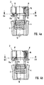
Gemäß Fig. 1 ist die Spindel 1 einer nicht näher gezeichneten Textilmaschine mit ihrem oberen Endbereich in den Hohlraum eines oberen Spulen-Adapters 2 mit hohlzylindrischer Grundform eingeschoben. Der obere Adapter 2 besteht im wesentlichen aus zwei zusammenhängenden gegeneinander axial verschiebbaren Teilen, nämlich dem oberen Verriegelungsteil 3 und dem unteren Spulenmitnahmeteil 4, der im Beispiel als hohlzylindrische Büchse mit im oberen Stirnbereich konischer Außenwandung 5 ausgeführt ist. Diese steht mit der gegenüberliegenden Innenwandung einer Garnspule 6 in reibschlüssigem Eingriff. Eine oder mehrere achsparallele oder koaxiale Druckfedern 7, die gegen die Unterseite des Verriegelungsteils 3 abgestützt sind, drücken den Spulenmitnahmeteil 4 mit seinem konischen Außenwandungsabschnitt 5 an die Innenwandung der Garnspule 6. Der Zusammenhang der genannten Teile 3 und 4 ist durch eine gegenseitige Verhakung 43 realisiert.1, the
Der Verriegelung bzw. Verrastung des oberen Adapters 2 mit der Spindel 1 dient als Einrastmittel ein Querschieber 8, der gemäß Fig. 2 in einer Querführung 9 senkrecht zur Adapter-Zylinderachse 10 verschiebbar ist. Der Schieber 8 besitzt gemäß Fig. 2 eine ringartige Lasche 11 mit einer mittigen Bohrung 12, welche die Spindel 1 umgibt. Zu diesem Zweck besitzt die Bohrung 12 einen größeren Durchmesser als die Spindel 1. Letztere ist in ihrem dem Adapter 2 zugeordneten Bereich mit einer Ringnut 13 versehen, in die gemäß Fig. 1 die Lasche 11 mit einem Teil 11a des die Bohrung 12 begrenzenden Innenumfangs eingerückt ist. Dieses Einrücken kann im Zuge des axialen Aufsteckens des Adapters 2 auf die Spindel 1 aufgrund der Querfeder 14 selbstätig erfolgen, die gegen den Außenmantel des Adapter-Grundkörpers abgestützt auf die Innenseite eines Schenkels des Schiebers 8 mit L-artigem Grundprofil im Axialschnitt drückt. Im nicht aufgestecktem Zustand (nicht gezeichnet) würde die Bohrung 12 der Schieberlasche 11 durch die Querfeder 14 nach radial außen außer Deckung mit der Zylinderachse 10 des Adapters 2 verstellt. Das Aufstecken des Adapters 2 mit Schieber 8 wird durch eine umlaufende, vorzugsweise konische Schrägfläche 15 erleichtert, die am Spindelende 16 ausgebildet ist. Die Schrägfläche 15 bewirkt eine Zentrierung insbesondere des Schiebers 8 mit seiner Bohrung 12 derart, daß dieser in Verbindung mit dem Querdruck der Querfeder 14 in die Ringnut 13 der Spindel 1 einrasten kann. Mittels ein oder mehrerer achsparallelen Fixier- und/oder Anschlagstifte 17, der den Adapter-Grundkörper und gegebenenfalls auch die Lasche 11 durchsetzt, kann neben der zusätzlichen Arretierung bzw. Verriegelung noch ein Ausgleich rotatorisch- asymmetrischer Masseverteilungen im Adapter-Grundkörper bewirkt werden. Die asymmetrischen Masseverteilungen gehen insbesondere auf die spezififsche Ausbildung des Querschiebers 8 und der asymmetrischen Anordnung der Querfeder 14 zurück. Demgegenüber können die Anschlag- und/oder Fixierstifte 17 die Funktion von Auswuchtkörpern ausführen.The locking or latching of the
Bei Spindeln ohne die genannte Schrägfläche kann die richtige Aufsteckposition durch manuellen Druck auf die Außenseite des Schiebers 8, wodurch dieser gegen die radial nach außen gerichtete Kraft der Querfeder 14 verschoben wird, erreicht werden. Zum Lösen der Verriegelung wird der Schieber 8 durch geringfügigen, manuellen Druck nach radial innen in eine Auslöseposition gebracht, in welcher die Fläche der mittigen Bohrung 12 den Querschnitt der Spindel 1 vollständig abdeckt bzw. die Lasche 11 die Ringnut bzw. die Spindel 1 nicht mehr berührt. Die Axial-Druckfeder 7 kann dann den Verriegelungsteil 3 gegenüber dem Mitnahmeteil 4 axial nach oben verschieben, um die Entriegelung bzw. Ausrastung des Schiebers 8 zu vollenden.In the case of spindles without said inclined surface, the correct plug-on position can be achieved by manual pressure on the outside of the
Gemäß Fig. 3 ist am unteren Ende der Spule 6 ein unterer Spulenadapter 18 ebenfalls mit einer konischen Außenwandung 5 angeordnet. Die Federkraft der Axialdruckfeder 7 gemäß Fig. 1, die sich über den eingerasteten Schieber 8 gegen die Ringnut 13 abstützt, bewirkt Reibschluß zwischen den konischen Außenwandungen 5 des oberen Adapters 2 und des unteren Adapters 18 und der jeweiligen Innenwandung der Garnspule 6.3, a
Gemäß Fig. 4a, 5a ist lediglich ein einziger Anschlag- und Fixierstift 17 vorgesehen, welcher den Verriegelungsteil 3 des Spulenadapters 2 achsparallel durchsetzt. Er bildet gleichsam ein Gegengewicht zur Querfeder 14 und den dadurch radial nach außen gedrückten Querschieber 8, wie insbesondere aus der in Fig. 5a gezeigten Stellung ersichtlich. In dieser Stellung ist der Einrastteil 11a der Ringlasche 11 in die Ringnut 13 eingerückt, und die mittige Bohrung 12 der Ringlasche 11 steht außer Deckung mit dem maximalen Querschnitt 100 der Spindel 1. In der Stellung nach Fig. 4b, 5b dagegen ist der Querschieber 8 bzw. die Ringlasche 11 beispielsweise mittels Fingerdruck gegen die Querfeder 14 radial nach innen derart gedrückt, daß sich die Bohrung 12 der Ringlasche 11 mit dem Spindelquerschnitt 100 so decken, daß der Spulenadapter 2 nach oben abgezogen werden kann, ohne daß ein Eingriffs- bzw. Einrückteil 11a der Ringlasche 11 dem im Wege stehen würde. Gemäß Fig. 4a, 4b besitzt der Fixier- und Anschlagstift 17 an seinem unteren, stirnseitigen Ende einen vorspringenden Anschlagzapfen 17a, der in ein Langloch 11b taucht, das zwischen dem äußeren Rand und der Bohrung 12 der Ringlasche ausgebildet ist. Die Längsrichtung des Langloches 11b verläuft etwa radial bezüglich der Bohrung 12 und/oder der Spindelachse 10. In der verriegelten Stellung gemäß Fig. 5a schlägt der Anschlagszapfen 17a im Langloch 11b etwa gegen dessen radial äußeres Ende, während in der Verriegelungsstellung 5b der gegen das radial innere Ende des Langloches 11b anliegt.4a, 5a, only a single stop and fixing
Die Ausführung nach Fig. 6 dient dazu, auf einer einzigen Spindel 1 Garnspulen 6a, 6b unterschiedlicher Länge aufnehmen zu können. Zu diesem Zweck ist die Spindel 1 im axialen Abstand voneinander mit zwei Ringnuten 13a und 13b als Rasteneinrichtungen versehen. Die obere Ringnut 13b dient zur axialen Verriegelung der längeren Garnspule 6b, die untere Ringnut 13a zur Verriegelung der kürzeren Garnspule 6a. Wegen sonstiger Einzelheiten und der Funktionsweise kann auf die vorher erläuterten Ausführungsbeispiele entsprechend verwiesen werden.The embodiment according to FIG. 6 serves to be able to take up 1
Auch gemäß den weiteren Ausbildungen gemäß Fig. 7 - 11 ist zur Verriegelung oder Entriegelung nur eine geradlinige, axiale Bewegung 29 notwendig.7 to 11, only a linear
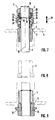
Gemäß Fig.7 erfolgt die Verriegelung mittels Einrastmittel, die als Kugelelemente 19 in kranz- oder ringartiger Anordnung mit gleichmäßiger Verteilung um die Zylinderachse 10 realisiert sind. Die Kugelelemente 19 werden im nicht verriegelten bzw. ausgerasteten Zustand beispielsweise in jeweils zugeordneten Führungstaschen 20 entsprechender, ringartiger Anordnung gehalten und unmittelbar vor Einrastung achsparallel zur Ringnut 13 der Spindel 1 geleitet. Dabei ist im Zuge des Aufsteckens des oberen Adapters 2 ein Sicherungsring 21 gegen den Druck einer oder mehrerer axialer oder achsparalleler Sicherungsfedern 22 nach oben geschoben. Damit werden den Kugelelementen 19 nicht mehr der Parallelabschnitt 23 der Sicherungsring-Innenwandung (parallel zur Zylinderachse 10), sondern der polygonal nachfolgende Schrägabschnitt 24 der Sicherungsring-Innenwandung gegenübergestellt. Der gegenüberliegende Schrägabschnitt 24 ermöglicht den Kugelelementen 19, in radialer Richtung nach außen zu treten, so daß sie aufgrund der Schwerkraftwirkung und des entstandenen Spieles nach unten auf die ringartige Auflageschulter 25 auftreffen können. Diese liegt bündig bzw. auf gleicher Höhe wie die untere Kante der Ringnut 13, die ähnlich wie nach Fig. 1 angeordnet ist. Sodann wird der beispielsweise manuell nach oben verschobene Sicherungsring 21 losgelassen und aufgrund der Schwerkraft und des Drucks der Sicherungsfeder 22 nach unten verfahren. Dabei gelangt der Innenwand-Parallelabschnitt des Sicherungsrings 21 in Anlage an die Kugelelemente 19, wodurch diese in die Ringnut 13 eingerückt werden. Eine radiale und somit auch axiale Bewegung der Kugelelemente 19 ist damit verhindert.According to FIG. 7, locking takes place by means of latching means, which are realized as
Zum Lösen der Verriegelung und des oberen Spulenadapters 2 wird der Sicherungsring 21 wieder nach oben geschoben. Dabei entstehen axiale Federkräfte sowohl aufgrund der Sicherungsfeder 22 als auch der Druckfeder 7. Insbesondere aufgrund letzterer wird die Auflageschulter 25 nach oben gerückt, wobei die Kugelelemente 19 aus der Ringnut 13 herausgestoßen und in ihre Führungstaschen 20 zurückgeführt werden können. Neben der einfachen Handhabung bringt diese rotationssymmetrische Spulenhalterung weitere Vorteile wie einfache, kostengünstige Fertigung und Vermeidung von Unwuchten und somit von Zentrifugalkräften.To release the lock and the
Gemäß Fig. 9 ist die untere Spulenhalterung 18 über Schraubmittel 26 lösbar auf die Spindelwelle aufgebracht. Diese formschlüssigen Verbindungselemente können in einfacher Weise die Kraft auf die Halterung übertragen. Bei Verschleiß der Reibfläche des Spulenmitnahmeteils 4 kann dieses nach Lösen der Schraubmittel 26 einfach ausgetauscht werden wie in Fig. 5 veranschaulicht. Bei der fest durch Kleben oder Pressen aufgebrachten Aufnahme (vgl. Fig. 3) wird diese vorzugsweise aus zwei Teilen gefertigt. Bei Verschleiß verbleibt der Kern auf der Welle, während ein äußerer Ring ausgetauscht wird.According to FIG. 9, the
Gemäß Fig. 10 sind die Einrastmittel als kranzartig um die Spindel 1 herum angeordnete Federhaken 27 ausgeführt. Deren oberer Schaftteil 28 ist an der Innenwandung des Verriegelungsteils befestigt. Durch diese Anlenkung kann der freie Hakenteil, wenn dem Adapter 2 bzw. 2a eine ausreichende Aufsteckbewegung 29 erteilt wird, in die Einkerbung 30 der Spindel 1 einschnappen bzw. einrasten. Diese verbreitert sich von der Oberkante 31 aus in Richtung zur Spindelmitte zunehmend, so daß die Oberkante 31 für das freie Hakenende der Federhaken 27 gleichsam einen Widerhaken bildet. Zum Lösen des Adapters 2 bzw. 2a wird ein zwischen Spindel 1 und Innenwandung des Adapters 2 bzw. 2a geführter Lösering 32 nach unten in Richtung zur Einkerbung 30 verschoben. Insbesondere aufgrund des etwa keilartigen Axialschnittprofils des Löserings 32 erfolgt mit zunehmender Verschiebung gemäß Aufsteckbewegung 29 eine Aufweitung der Federhaken 27 nach radial außen, so daß deren freie Hakenende außer Eingriff mit der Oberkante 31 bzw. dem Widerhaken der Einkerbung 30 gelangen. In diesem Zustand ist eine Abziehbewegung nach oben entgegengesetzt zur Aufsteckbewegung 29 nach unten möglich, um einen Austausch der Garnspule 6 vorzunehmen.According to FIG. 10, the latching means are designed as spring hooks 27 arranged around the
Gemäß linker Hälften der Fig. 10 und 11 ist die Axialdruckfeder 7 im Verriegelungsteil 3 des Spulenadapters 2 baulich integriert und erzeugt die zum Reibschluß zwischen konischer Außenwandung 5 und Innenseite der Garnspule 6 notwendige Axialkraft. Gemäß rechte Hälften der Fig. 10 und 11 ist im unteren Adapter 18a eine Axialdruckfeder 7a mit gleichartiger Funktion zur Herbeiführung des Reibschlußes zwischen konischen Außenwandungen 5 und Innenwandungen der Garnspulen 6 angeordnet. Dann kann im oberen Spulenadapter 2a eine Axialdruckfeder entfallen, muß aber nicht.According to the left halves of FIGS. 10 and 11, the
Claims (20)
Applications Claiming Priority (2)
| Application Number | Priority Date | Filing Date | Title |
|---|---|---|---|
| DE19530140 | 1995-08-16 | ||
| DE19530140 | 1995-08-16 |
Publications (3)
| Publication Number | Publication Date |
|---|---|
| EP0712802A2 true EP0712802A2 (en) | 1996-05-22 |
| EP0712802A3 EP0712802A3 (en) | 1997-01-08 |
| EP0712802B1 EP0712802B1 (en) | 2000-03-22 |
Family
ID=7769628
Family Applications (1)
| Application Number | Title | Priority Date | Filing Date |
|---|---|---|---|
| EP96100312A Expired - Lifetime EP0712802B1 (en) | 1995-08-16 | 1996-01-11 | Bobbin adapter |
Country Status (6)
| Country | Link |
|---|---|
| US (1) | US5718108A (en) |
| EP (1) | EP0712802B1 (en) |
| JP (1) | JPH0952659A (en) |
| CN (1) | CN1143128A (en) |
| AT (1) | ATE190964T1 (en) |
| DE (2) | DE59604715D1 (en) |
Cited By (1)
| Publication number | Priority date | Publication date | Assignee | Title |
|---|---|---|---|---|
| EP1982943A3 (en) * | 2007-04-20 | 2009-11-04 | Oerlikon Textile GmbH & Co. KG | Spooling device for a workstation of a textile machine for creating cross-wound spools |
Families Citing this family (18)
| Publication number | Priority date | Publication date | Assignee | Title |
|---|---|---|---|---|
| DE10154654B4 (en) * | 2001-10-31 | 2010-11-25 | Novibra Gmbh | Spindle upper part of a spinning or twisting spindle and spool sleeve for use with the spindle top part |
| DE10248929A1 (en) * | 2002-10-15 | 2004-04-29 | Wilhelm Stahlecker Gmbh | Drive coupling for spinning or twisting spindle comprises projections inside yarn tube engaging recesses near top of spindle |
| US7140573B1 (en) * | 2003-01-10 | 2006-11-28 | Helen Of Troy Limited | Rotating article dispenser |
| DE102004031253A1 (en) * | 2004-06-29 | 2006-01-19 | Texparts Gmbh | sleeve coupling |
| US7401749B2 (en) * | 2005-02-09 | 2008-07-22 | Simplehuman Llc | Holder for paper towel rolls with a quick-release retractable handle |
| US7530525B2 (en) * | 2005-03-29 | 2009-05-12 | Simplehuman Llc | Holder for paper towel rolls |
| ITFI20070134A1 (en) * | 2007-06-15 | 2008-12-16 | Mariella Crotti | "MELT FOR THE WINDING OF YARNS ON TUBES OR TUBULAR WINDOWS" |
| DE102008060803A1 (en) * | 2008-12-01 | 2010-06-02 | C. & E. Fein Gmbh | Coil for a winding device |
| CN102616612A (en) * | 2012-03-31 | 2012-08-01 | 镇江耐丝新型材料有限公司 | Switching device for spools with different diameters |
| CN102976167A (en) * | 2012-12-03 | 2013-03-20 | 吴江市东飞化纤有限公司 | Combined-type bobbin |
| CN104131372A (en) * | 2014-08-08 | 2014-11-05 | 湖州市菱湖石淙永盛丝织厂 | Spindle capable of absorbing vibration |
| CN104131373A (en) * | 2014-08-08 | 2014-11-05 | 湖州市菱湖石淙永盛丝织厂 | Spindle with shock absorption device |
| US10889460B2 (en) * | 2016-11-03 | 2021-01-12 | Eric Martin Ferguson | Material handling device |
| CN106429623A (en) * | 2016-12-02 | 2017-02-22 | 张家港特恩驰电缆有限公司 | Cylinder ejecting shaft device |
| CN106757579B (en) * | 2016-12-23 | 2018-11-20 | 晋中经纬恒腾纺机有限公司 | bobbin spindle connector |
| CN109320055A (en) * | 2018-11-22 | 2019-02-12 | 重庆家喜陶瓷制品有限公司合川分公司 | A kind of pickle jar punch for producing cooler |
| CN113697587B (en) * | 2021-09-17 | 2023-04-18 | 绍兴中煜化纤股份有限公司 | Yarn frame for textile machine |
| CN114086295B (en) * | 2021-11-18 | 2023-12-15 | 雁峰集团有限公司 | Shuttle for circular loom and circular loom |
Citations (8)
| Publication number | Priority date | Publication date | Assignee | Title |
|---|---|---|---|---|
| US1898115A (en) * | 1929-12-26 | 1933-02-21 | Whitin Machine Works | Retaining device for twister spindles |
| US1898131A (en) * | 1931-02-16 | 1933-02-21 | Whitin Machine Works | Locking device for bobbin caps |
| US2577571A (en) * | 1949-09-22 | 1951-12-04 | Du Pont | Apparatus for yarn twisting |
| DE1666078U (en) * | 1953-08-25 | 1953-10-29 | Debomit G M B H | REEL HOLDER. |
| DE2261559A1 (en) * | 1972-12-15 | 1974-06-20 | Windmoeller & Hoelscher | CARRYING SHAFT FOR GOOD COILED ON SLEEVES |
| DE7409733U (en) * | 1974-03-20 | 1975-09-11 | Kugelfischer G Schaefer & Co | Holding and centering device for spools of textile machines |
| DE3132159A1 (en) * | 1981-08-14 | 1983-03-03 | FAG Kugelfischer Georg Schäfer & Co, 8720 Schweinfurt | Bobbin safeguard |
| DE9016205U1 (en) * | 1990-11-29 | 1991-02-14 | Fag Kugelfischer Georg Schaefer Kgaa, 8720 Schweinfurt, De |
Family Cites Families (8)
| Publication number | Priority date | Publication date | Assignee | Title |
|---|---|---|---|---|
| DE808133C (en) * | 1949-04-07 | 1951-07-12 | Hackethal Draht Und Kabel Werk | Paper spinners, in particular for placing paper tapes on electrical conductors |
| US3596846A (en) * | 1969-03-03 | 1971-08-03 | Stromberg Datagraphix Inc | Retaining device |
| US3731502A (en) * | 1972-02-24 | 1973-05-08 | Macon Machine Co | Releasable locking assembly |
| US4423609A (en) * | 1981-12-04 | 1984-01-03 | Osaka Bobbin Kabushiki Kaisha | Single-operation type of fastening device for bobbin spacer |
| US4720986A (en) * | 1984-06-12 | 1988-01-26 | Maschinenfabrik Scharer Ag | Spool mounting apparatus and method of using the same |
| IT1183624B (en) * | 1985-05-14 | 1987-10-22 | Carlo Menegatto | CENTRIFUGAL COIL LOCKING DEVICE |
| US4762179A (en) * | 1986-08-04 | 1988-08-09 | Halliburton Company | Pressure assist detonating bar and method for a tubing conveyed perforator |
| US5477709A (en) * | 1994-02-28 | 1995-12-26 | Mid-Atlantic Tool & Die, Inc. | Locking assembly for securing and sealing spools to a spindle during a dyeing operation |
-
1996
- 1996-01-11 EP EP96100312A patent/EP0712802B1/en not_active Expired - Lifetime
- 1996-01-11 AT AT96100312T patent/ATE190964T1/en not_active IP Right Cessation
- 1996-01-11 DE DE59604715T patent/DE59604715D1/en not_active Expired - Fee Related
- 1996-01-12 US US08/586,006 patent/US5718108A/en not_active Expired - Fee Related
- 1996-01-17 DE DE29600744U patent/DE29600744U1/en not_active Expired - Lifetime
- 1996-02-13 CN CN96101263A patent/CN1143128A/en active Pending
- 1996-03-27 JP JP8071847A patent/JPH0952659A/en active Pending
Patent Citations (8)
| Publication number | Priority date | Publication date | Assignee | Title |
|---|---|---|---|---|
| US1898115A (en) * | 1929-12-26 | 1933-02-21 | Whitin Machine Works | Retaining device for twister spindles |
| US1898131A (en) * | 1931-02-16 | 1933-02-21 | Whitin Machine Works | Locking device for bobbin caps |
| US2577571A (en) * | 1949-09-22 | 1951-12-04 | Du Pont | Apparatus for yarn twisting |
| DE1666078U (en) * | 1953-08-25 | 1953-10-29 | Debomit G M B H | REEL HOLDER. |
| DE2261559A1 (en) * | 1972-12-15 | 1974-06-20 | Windmoeller & Hoelscher | CARRYING SHAFT FOR GOOD COILED ON SLEEVES |
| DE7409733U (en) * | 1974-03-20 | 1975-09-11 | Kugelfischer G Schaefer & Co | Holding and centering device for spools of textile machines |
| DE3132159A1 (en) * | 1981-08-14 | 1983-03-03 | FAG Kugelfischer Georg Schäfer & Co, 8720 Schweinfurt | Bobbin safeguard |
| DE9016205U1 (en) * | 1990-11-29 | 1991-02-14 | Fag Kugelfischer Georg Schaefer Kgaa, 8720 Schweinfurt, De |
Cited By (1)
| Publication number | Priority date | Publication date | Assignee | Title |
|---|---|---|---|---|
| EP1982943A3 (en) * | 2007-04-20 | 2009-11-04 | Oerlikon Textile GmbH & Co. KG | Spooling device for a workstation of a textile machine for creating cross-wound spools |
Also Published As
| Publication number | Publication date |
|---|---|
| DE29600744U1 (en) | 1996-05-09 |
| JPH0952659A (en) | 1997-02-25 |
| CN1143128A (en) | 1997-02-19 |
| EP0712802B1 (en) | 2000-03-22 |
| DE59604715D1 (en) | 2000-04-27 |
| US5718108A (en) | 1998-02-17 |
| EP0712802A3 (en) | 1997-01-08 |
| ATE190964T1 (en) | 2000-04-15 |
Similar Documents
| Publication | Publication Date | Title |
|---|---|---|
| EP0712802A2 (en) | Support for yarn bobbins rotating at high speed in textile machines and associated bobbin adapter | |
| EP0500489B1 (en) | Tool and toolholder for hand held machine | |
| AT393788B (en) | DENTAL HANDPIECE WITH DETACHABLE HANDPIECE SLEEVE | |
| DE10031027A1 (en) | Spindle in a machine tool | |
| DE3507817A1 (en) | DRILL FOR PRODUCING AN UNDERCUT IN A HOLE | |
| EP1709931B1 (en) | Motor element, in particular dental hand piece with a releasable coupling for a tool holder | |
| DE3814550C1 (en) | Clamping device for clamping two machine parts releasable from one another | |
| DE3835879C1 (en) | ||
| DE3632045C1 (en) | Device for connecting two tool parts | |
| EP0789986B1 (en) | Tractor hitch lift link | |
| DE2620050C2 (en) | ||
| DE19636594A1 (en) | Release unit | |
| EP0428856B1 (en) | Tractor lift rod | |
| DE3839681C2 (en) | ||
| EP1279363B1 (en) | Apparatus for fixing a brush body to the housing of a floor cleaning device | |
| DE19918638C2 (en) | Connector for a drill for drilling holes in bone tissue, drill and drill | |
| EP0350786B1 (en) | Bobin winding device | |
| CH681504A5 (en) | ||
| EP3515372B1 (en) | Prosthesis coupling for a prosthesis, and prosthesis with the prosthesis coupling | |
| EP1140431A1 (en) | Chuck for exchangeable tool inserts | |
| EP1273686B1 (en) | Opening roller | |
| EP0776775B1 (en) | Wheel bearing | |
| EP0734815A1 (en) | Pulling tool for removing bearings | |
| DE3318745C2 (en) | Planing machine, in particular hand planer | |
| EP3165638A1 (en) | Spindelschaft, spinnhülse und formwerkzeug |
Legal Events
| Date | Code | Title | Description |
|---|---|---|---|
| PUAI | Public reference made under article 153(3) epc to a published international application that has entered the european phase |
Free format text: ORIGINAL CODE: 0009012 |
|
| AK | Designated contracting states |
Kind code of ref document: A2 Designated state(s): AT CH DE ES FR GB IT LI |
|
| PUAL | Search report despatched |
Free format text: ORIGINAL CODE: 0009013 |
|
| AK | Designated contracting states |
Kind code of ref document: A3 Designated state(s): AT CH DE ES FR GB IT LI |
|
| 17P | Request for examination filed |
Effective date: 19970708 |
|
| 17Q | First examination report despatched |
Effective date: 19980729 |
|
| GRAG | Despatch of communication of intention to grant |
Free format text: ORIGINAL CODE: EPIDOS AGRA |
|
| GRAG | Despatch of communication of intention to grant |
Free format text: ORIGINAL CODE: EPIDOS AGRA |
|
| GRAH | Despatch of communication of intention to grant a patent |
Free format text: ORIGINAL CODE: EPIDOS IGRA |
|
| GRAH | Despatch of communication of intention to grant a patent |
Free format text: ORIGINAL CODE: EPIDOS IGRA |
|
| RAP1 | Party data changed (applicant data changed or rights of an application transferred) |
Owner name: TEMCO TEXTILMASCHINENKOMPONENTEN GMBH |
|
| GRAA | (expected) grant |
Free format text: ORIGINAL CODE: 0009210 |
|
| AK | Designated contracting states |
Kind code of ref document: B1 Designated state(s): AT CH DE ES FR GB IT LI |
|
| PG25 | Lapsed in a contracting state [announced via postgrant information from national office to epo] |
Ref country code: ES Free format text: THE PATENT HAS BEEN ANNULLED BY A DECISION OF A NATIONAL AUTHORITY Effective date: 20000322 |
|
| REF | Corresponds to: |
Ref document number: 190964 Country of ref document: AT Date of ref document: 20000415 Kind code of ref document: T |
|
| REG | Reference to a national code |
Ref country code: CH Ref legal event code: EP |
|
| REF | Corresponds to: |
Ref document number: 59604715 Country of ref document: DE Date of ref document: 20000427 |
|
| REG | Reference to a national code |
Ref country code: CH Ref legal event code: NV Representative=s name: ISLER & PEDRAZZINI AG |
|
| GBT | Gb: translation of ep patent filed (gb section 77(6)(a)/1977) |
Effective date: 20000525 |
|
| ITF | It: translation for a ep patent filed |
Owner name: SOCIETA' ITALIANA BREVETTI S.P.A. |
|
| ET | Fr: translation filed | ||
| PG25 | Lapsed in a contracting state [announced via postgrant information from national office to epo] |
Ref country code: AT Free format text: LAPSE BECAUSE OF NON-PAYMENT OF DUE FEES Effective date: 20010111 |
|
| PGFP | Annual fee paid to national office [announced via postgrant information from national office to epo] |
Ref country code: GB Payment date: 20010119 Year of fee payment: 6 |
|
| PLBE | No opposition filed within time limit |
Free format text: ORIGINAL CODE: 0009261 |
|
| STAA | Information on the status of an ep patent application or granted ep patent |
Free format text: STATUS: NO OPPOSITION FILED WITHIN TIME LIMIT |
|
| PGFP | Annual fee paid to national office [announced via postgrant information from national office to epo] |
Ref country code: FR Payment date: 20010125 Year of fee payment: 6 Ref country code: CH Payment date: 20010125 Year of fee payment: 6 |
|
| 26N | No opposition filed | ||
| REG | Reference to a national code |
Ref country code: GB Ref legal event code: IF02 |
|
| PG25 | Lapsed in a contracting state [announced via postgrant information from national office to epo] |
Ref country code: GB Free format text: LAPSE BECAUSE OF NON-PAYMENT OF DUE FEES Effective date: 20020111 |
|
| PG25 | Lapsed in a contracting state [announced via postgrant information from national office to epo] |
Ref country code: LI Free format text: LAPSE BECAUSE OF NON-PAYMENT OF DUE FEES Effective date: 20020131 Ref country code: CH Free format text: LAPSE BECAUSE OF NON-PAYMENT OF DUE FEES Effective date: 20020131 |
|
| GBPC | Gb: european patent ceased through non-payment of renewal fee |
Effective date: 20020111 |
|
| REG | Reference to a national code |
Ref country code: CH Ref legal event code: PL |
|
| PG25 | Lapsed in a contracting state [announced via postgrant information from national office to epo] |
Ref country code: FR Free format text: LAPSE BECAUSE OF NON-PAYMENT OF DUE FEES Effective date: 20020930 |
|
| REG | Reference to a national code |
Ref country code: FR Ref legal event code: ST |
|
| PGFP | Annual fee paid to national office [announced via postgrant information from national office to epo] |
Ref country code: DE Payment date: 20040317 Year of fee payment: 9 |
|
| PG25 | Lapsed in a contracting state [announced via postgrant information from national office to epo] |
Ref country code: IT Free format text: LAPSE BECAUSE OF NON-PAYMENT OF DUE FEES;WARNING: LAPSES OF ITALIAN PATENTS WITH EFFECTIVE DATE BEFORE 2007 MAY HAVE OCCURRED AT ANY TIME BEFORE 2007. THE CORRECT EFFECTIVE DATE MAY BE DIFFERENT FROM THE ONE RECORDED. Effective date: 20050111 |
|
| PG25 | Lapsed in a contracting state [announced via postgrant information from national office to epo] |
Ref country code: DE Free format text: LAPSE BECAUSE OF NON-PAYMENT OF DUE FEES Effective date: 20050802 |