EP0705893A2 - Feuille détachable - Google Patents
Feuille détachable Download PDFInfo
- Publication number
- EP0705893A2 EP0705893A2 EP95115539A EP95115539A EP0705893A2 EP 0705893 A2 EP0705893 A2 EP 0705893A2 EP 95115539 A EP95115539 A EP 95115539A EP 95115539 A EP95115539 A EP 95115539A EP 0705893 A2 EP0705893 A2 EP 0705893A2
- Authority
- EP
- European Patent Office
- Prior art keywords
- layer
- releasing sheet
- backing layer
- tape
- backing
- Prior art date
- Legal status (The legal status is an assumption and is not a legal conclusion. Google has not performed a legal analysis and makes no representation as to the accuracy of the status listed.)
- Granted
Links
Images


Classifications
-
- C—CHEMISTRY; METALLURGY
- C09—DYES; PAINTS; POLISHES; NATURAL RESINS; ADHESIVES; COMPOSITIONS NOT OTHERWISE PROVIDED FOR; APPLICATIONS OF MATERIALS NOT OTHERWISE PROVIDED FOR
- C09J—ADHESIVES; NON-MECHANICAL ASPECTS OF ADHESIVE PROCESSES IN GENERAL; ADHESIVE PROCESSES NOT PROVIDED FOR ELSEWHERE; USE OF MATERIALS AS ADHESIVES
- C09J7/00—Adhesives in the form of films or foils
- C09J7/40—Adhesives in the form of films or foils characterised by release liners
- C09J7/405—Adhesives in the form of films or foils characterised by release liners characterised by the substrate of the release liner
-
- C—CHEMISTRY; METALLURGY
- C09—DYES; PAINTS; POLISHES; NATURAL RESINS; ADHESIVES; COMPOSITIONS NOT OTHERWISE PROVIDED FOR; APPLICATIONS OF MATERIALS NOT OTHERWISE PROVIDED FOR
- C09J—ADHESIVES; NON-MECHANICAL ASPECTS OF ADHESIVE PROCESSES IN GENERAL; ADHESIVE PROCESSES NOT PROVIDED FOR ELSEWHERE; USE OF MATERIALS AS ADHESIVES
- C09J2203/00—Applications of adhesives in processes or use of adhesives in the form of films or foils
- C09J2203/334—Applications of adhesives in processes or use of adhesives in the form of films or foils as a label
-
- C—CHEMISTRY; METALLURGY
- C09—DYES; PAINTS; POLISHES; NATURAL RESINS; ADHESIVES; COMPOSITIONS NOT OTHERWISE PROVIDED FOR; APPLICATIONS OF MATERIALS NOT OTHERWISE PROVIDED FOR
- C09J—ADHESIVES; NON-MECHANICAL ASPECTS OF ADHESIVE PROCESSES IN GENERAL; ADHESIVE PROCESSES NOT PROVIDED FOR ELSEWHERE; USE OF MATERIALS AS ADHESIVES
- C09J2400/00—Presence of inorganic and organic materials
- C09J2400/10—Presence of inorganic materials
- C09J2400/16—Metal
- C09J2400/163—Metal in the substrate
-
- C—CHEMISTRY; METALLURGY
- C09—DYES; PAINTS; POLISHES; NATURAL RESINS; ADHESIVES; COMPOSITIONS NOT OTHERWISE PROVIDED FOR; APPLICATIONS OF MATERIALS NOT OTHERWISE PROVIDED FOR
- C09J—ADHESIVES; NON-MECHANICAL ASPECTS OF ADHESIVE PROCESSES IN GENERAL; ADHESIVE PROCESSES NOT PROVIDED FOR ELSEWHERE; USE OF MATERIALS AS ADHESIVES
- C09J2400/00—Presence of inorganic and organic materials
- C09J2400/20—Presence of organic materials
- C09J2400/28—Presence of paper
- C09J2400/283—Presence of paper in the substrate
-
- Y—GENERAL TAGGING OF NEW TECHNOLOGICAL DEVELOPMENTS; GENERAL TAGGING OF CROSS-SECTIONAL TECHNOLOGIES SPANNING OVER SEVERAL SECTIONS OF THE IPC; TECHNICAL SUBJECTS COVERED BY FORMER USPC CROSS-REFERENCE ART COLLECTIONS [XRACs] AND DIGESTS
- Y10—TECHNICAL SUBJECTS COVERED BY FORMER USPC
- Y10T—TECHNICAL SUBJECTS COVERED BY FORMER US CLASSIFICATION
- Y10T428/00—Stock material or miscellaneous articles
- Y10T428/14—Layer or component removable to expose adhesive
- Y10T428/1476—Release layer
-
- Y—GENERAL TAGGING OF NEW TECHNOLOGICAL DEVELOPMENTS; GENERAL TAGGING OF CROSS-SECTIONAL TECHNOLOGIES SPANNING OVER SEVERAL SECTIONS OF THE IPC; TECHNICAL SUBJECTS COVERED BY FORMER USPC CROSS-REFERENCE ART COLLECTIONS [XRACs] AND DIGESTS
- Y10—TECHNICAL SUBJECTS COVERED BY FORMER USPC
- Y10T—TECHNICAL SUBJECTS COVERED BY FORMER US CLASSIFICATION
- Y10T428/00—Stock material or miscellaneous articles
- Y10T428/24—Structurally defined web or sheet [e.g., overall dimension, etc.]
- Y10T428/24802—Discontinuous or differential coating, impregnation or bond [e.g., artwork, printing, retouched photograph, etc.]
- Y10T428/24851—Intermediate layer is discontinuous or differential
- Y10T428/2486—Intermediate layer is discontinuous or differential with outer strippable or release layer
Definitions
- the present invention relates to a releasing sheet that is applied to the adhesive portions of adhesive labels or sheets.
- Adhesive labels or sheets made by applying an adhesive to a first side of a label or sheet backing, are known in the art.
- the second side of the label or sheet has a printing surface, and a releasing sheet is usually attached to the adhesive side to temporarily cover the adhesive.
- Such adhesive labels or sheets may be used with word processors or typewriters to produce labels for files and the like. Desired characters and figures are printed on the printing surface of the label, for instance by a printer connected to a personal computer, the printed adhesive label or sheet is cut to a desired size and shape, and the labels are adhered to objects such as files by peeling off the releasing sheet and pressing the adhesive side of the label against the object.
- the tape printer includes a tape printing unit 20 having a thermal head 21, and a tape cassette 22 that is removably mounted on the tape printing unit 20.
- the tape cassette 22 is shown without its top cover.
- the tape cassette 22 houses a tape spool 24, around which a transparent film tape 23 is wound, a ribbon supply spool 26, around which a thermal transfer ribbon 25 is wound with its ink surface facing inward, a ribbon take-up spool 27 for taking up the thermal transfer ribbon 25 withdrawn from the ribbon supply spool 26, a double-sided adhesive tape spool 29, around which is wound a double-sided adhesive tape 28 having substantially the same width as that of the transparent film tape 23 and a releasing sheet adhered to the outward facing side, and an alignment roller 30 for aligning the double-sided adhesive tape 28 with the transparent film tape 23.
- Each of the above spools is rotatably supported between the top cover (not shown) and a support section (not shown) of the tape cassette.
- the thermal head 21 can be inserted into an indented section 31 formed on the tape cassette 22.
- a feed roller 33 and a platen roller 34 which are provided on a support body 32 that is rotatably supported on the tape printing unit 20.
- the platen roller 34 and feed roller 33 are arranged opposite to the thermal head 21 and the alignment roller 30, respectively.
- the support body 32 is urged against the tape cassette 22 by an urging member (not shown).
- the platen roller 34 is pressed against the thermal head 21, whereas the feed roller 33 is pressed against the alignment roller 30.
- the thermal head 21 commences print control upon the depression of a print key (not shown) after desired characters have been input.
- the transparent film tape 23 is withdrawn from the spool 24 and fed to the thermal head 21 and the platen roller 34 by means of the alignment roller 30 and the feed roller 33.
- the thermal transfer ribbon 25 is withdrawn from the ribbon supply spool 26 and fed toward the thermal head 21 and the platen roller 34 at the same speed as the transparent film tape 23.
- Characters or the like are then printed on the transparent film tape 23 via the thermal transfer ribbon 25 and the thermal head 21 in synchronism with the feeding operation of the transparent film tape 23 and the thermal transfer ribbon 25.
- the printed film tape 23 is then fed to the alignment roller 30 and the feed roller 33.
- the double-sided adhesive tape 28 is withdrawn from the double-sided adhesive tape spool 29 by the cooperative action of the alignment roller 30 and the feed roller 33.
- a first adhesive surface of the double-sided adhesive tape 28 is aligned with and affixed to the printed surface of the transparent film tape 23. In this way, an adhesive label P is prepared.
- the alignment roller 30 and the releasing sheet of the double-sided adhesive tape 28 come into contact with each other.
- the releasing sheet of the adhesive label or sheet comes into contact with various members such as a platen and feed rollers which are disposed in a traveling path of the typewriter, word processor or printer.
- the releasing sheet of the adhesive labels or tapes described above have a significantly different electrostatic charge pattern than the platen or feed rollers, the probability that static electricity will be generated on the releasing sheet is high. Particularly, if a so-called transfer coating method is employed to form the adhesive labels or tapes. The development of static electricity becomes even more likely during low temperature and low humidity conditions.
- a transfer coating method an adhesive is first applied to a releasing sheet, the coated sheet is dried, and the dried coated releasing sheet is affixed to a label or tape backing.
- moisture contained in the releasing sheet will be significantly decreased during the drying step as a result of evaporation. This will, in turn, considerably increase the probability of generation of static electricity.
- the static electricity generated during the printing tends to cause the adhesive label or tape to adhere to the platen, the feed roller, or the like.
- the adhesive label or tape may get caught up in the platen or the feed roller. If this happens, feeding of the label or tape may be affected, and misprinting may occur. It will become impossible to decipher the printed characters or figures due to a deficiency in feed rate.
- handling of the adhesive sheet or label becomes extremely troublesome. Additionally, the resulting charged adhesive label or sheet attracts dirt or dust.
- the present invention is aimed at solving the above-mentioned problems, and providing a releasing sheet which does not lose its antistatic properties when it passes through a dryer during an adhesive coating process, or when it is stored for long periods of time in extremely dry conditions.
- a releasing sheet embodying the present invention includes a paper backing that is mixed with a conductive filler, and a separation layer that is formed on the paper backing.
- the conductive filler may comprise metal powder, conductive carbon black, or any other similar substance.
- a releasing sheet embodying the invention may also include a coloring layer, such as a white pigment, formed between the paper backing and the separation layer.
- a releasing sheet embodying the invention may also be given an antistatic treatment.
- the surface electrical resistance of the paper backing on which the separation layer is not formed should preferably be less than 1.0 x 10¹² ⁇ .
- the releasing sheet of the present invention is attached to a printed transparent label or tape that has letters and figures printed thereon, it will be easy to see the characters and figures against the colored background.
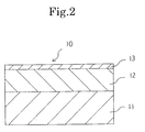
- the structure of antistatic releasing sheets that embody the invention are shown in Figures 1 and 2.
- the releasing sheet 10 shown in Fig. 1 comprises a paper backing 11 that is mixed with a conductive filler, and a separation layer 13.
- a colored layer 12 may be provided between the paper backing 11 and the separation layer 13.
- any paper is acceptable as the paper backing 11 so long as it is mixed with a conductive filler.
- normal high quality paper, or glassine paper could be used to form a releasing sheet embodying the invention.
- Suitable conductive fillers include metal powder such as conductive carbon black, graphite, gold, platinum, silver, nickel, copper, aluminum, zinc, iron or palladium. Conductive carbon black is one preferred conductive filler.
- the separation layer 13 may be formed from a coating of a silicone resin or other similar or equivalent substance having an ordinary releasing property.
- the separation layer 13 may be formed either directly on the paper backing 11, as shown in Fig. 1, or on an intervening colored layer 12, as shown in Fig. 2, employing any known coating system.
- the colored layer 12 may be formed on the paper backing 11 by coating the paper backing 11 with a paint which includes a color pigment, or by carrying out known extrusion lamination process using a resin mixed with a color pigment.
- the formation of the colored layer 12 on the paper backing 11 makes the separation layer 13 side appear colored.
- the colored layer 12 ensures that when a printed transparent label is attached to the separation layer 13 via an adhesive layer, characters and figures on the transparent label are easy to identify.
- the pigment may comprise metal oxides of titanium, aluminum, zinc, zirconium or magnesium, or the oxide may comprise calcium carbonate, barium sulfate, talc, clay, bentonite, or the like. In terms of opaqueness, titanium oxide is more desirable. Of course, colors other than white could be used.
- a resin suitable for use in a lamination process are polyethylene, polypropylene, ionomer, an ethylene-vinyl acetate copolymer, an ethylene-ethyl acrylate copolymer, an ethylene acrylate copolymer, nylon, polyester, or the like.
- polyethylene is preferred.
- a colored label 16 utilizing an antistatic releasing sheet 10 embodying the invention was constructed as shown in Figure 4.
- the colored label 16 was formed by applying a colored layer 12 to a paper backing 11 mixed with conductive carbon black.
- a separation layer 13 was then formed on the colored layer 12 by applying a silicone resin to the colored layer 12.
- the antistatic releasing sheet 10 was then laminated to a film 14 that was coated with a heat sensitive coloring agent (which is normally transparent but which turns black when heated) using an adhesive layer 15.
- the resulting colored label 16 was then dried at a temperature of about 100°C.
- the surface electrical resistance of the paper backing 11 was 1.0 x 10¹² ⁇ .
- This heat sensitive colored label 16 was kept in an environment of 5°C and 10% Rh (Relative humidity) for more than 48 hours. Thereafter, a printing test was carried out in a thermal transfer printer. Absolutely no generation of static electricity was observed on the label, and the label was sufficiently fed without becoming attracted to the feed rollers or the platen due to static electricity. Feeding never became impracticable. Further, the thermal transfer printer could carry out printing without the occurrence of malfunctions due to electrical discharges from the buildup of static electricity.
- the heat sensitive label used in the experiment was colorless and transparent, it was easy to identify black characters and figures printed on the label because of the colored layer 12 provided between the black antistatic releasing sheet 10 and the separation layer 13.
- the labels were kept in an environment of 5°C and 10% Rh for a period of more than 48 hours, and a printing test was carried out using a thermal transfer printer. All three of the colored labels generated static electricity during printing. As a result, the labels were attracted to the feed rollers and the platen in the thermal transfer printer. Poor traveling properties such as a lowered feed rate and impracticable feeding were observed. Accordingly, the letters and figures printed on the labels were remarkably impaired.
- a releasing sheet embodying the present invention may be attached to a double-sided adhesive tape 28 and used on the spool 29 of the tape cassette 22 shown in Fig. 2.
- the double-sided adhesive tape 28 and the transparent film tape 23 are press-fitted by the alignment roller 30 and the feed roller 33.
- a releasing sheet embodying the present invention may also be used in the printer and cassette shown in Fig. 5.
- the releasing sheet is bonded to a film tape, and the combined releasing sheet and film tape is wound, as a print tape 42, around a tape spool 43, with the releasing sheet facing outside.
- An ink ribbon 44 is wound around an ink ribbon feed spool 45.
- a take-up spool 46 takes up the ink ribbon.
- the print tape 42 and the ink ribbon 44 are superimposed, and printing is carried out by the thermal head 21 on the platen roller 41.
- the releasing sheet of the present invention has an antistatic effect by virtue of the conductive filler mixed in the paper backing.
- the tape is free from problems such as insufficient feed rate or impracticable tape feeding due to the development of static electricity.
- a colored layer such as a white pigment, may be formed between the paper backing and the separation layer so that characters and symbols printed on a transparent film attached to the releasing sheet will be visible against the colored background.
Landscapes
- Chemical & Material Sciences (AREA)
- Organic Chemistry (AREA)
- Laminated Bodies (AREA)
- Thermal Transfer Or Thermal Recording In General (AREA)
- Impression-Transfer Materials And Handling Thereof (AREA)
- Adhesive Tapes (AREA)
- Paper (AREA)
Applications Claiming Priority (3)
| Application Number | Priority Date | Filing Date | Title |
|---|---|---|---|
| JP238923/94 | 1994-10-03 | ||
| JP23892394 | 1994-10-03 | ||
| JP6238923A JPH08109599A (ja) | 1994-10-03 | 1994-10-03 | 帯電防止剥離紙 |
Publications (3)
| Publication Number | Publication Date |
|---|---|
| EP0705893A2 true EP0705893A2 (fr) | 1996-04-10 |
| EP0705893A3 EP0705893A3 (fr) | 1997-04-23 |
| EP0705893B1 EP0705893B1 (fr) | 2000-05-03 |
Family
ID=17037288
Family Applications (1)
| Application Number | Title | Priority Date | Filing Date |
|---|---|---|---|
| EP95115539A Expired - Lifetime EP0705893B1 (fr) | 1994-10-03 | 1995-10-02 | Feuille détachable |
Country Status (4)
| Country | Link |
|---|---|
| US (1) | US5593241A (fr) |
| EP (1) | EP0705893B1 (fr) |
| JP (1) | JPH08109599A (fr) |
| DE (1) | DE69516619T2 (fr) |
Cited By (1)
| Publication number | Priority date | Publication date | Assignee | Title |
|---|---|---|---|---|
| US6656556B2 (en) * | 2000-07-11 | 2003-12-02 | Lintec Corporation | Optically transparent pressure sensitive adhesive sheet for use in heat transfer image pattern formation and optically transparent decorative pressure sensitive adhesive sheet |
Families Citing this family (7)
| Publication number | Priority date | Publication date | Assignee | Title |
|---|---|---|---|---|
| US5683776A (en) * | 1996-09-06 | 1997-11-04 | Kikokaseisangyou Co., Ltd. | composite film for color copying |
| US5794981A (en) * | 1997-02-19 | 1998-08-18 | Lps Industries Inc. | Packaging system for protection against theft by overlabeling |
| US6190065B1 (en) * | 1998-03-27 | 2001-02-20 | Kroy Llc | Thermal imaging tape cartridge |
| CN1680111B (zh) * | 1999-08-06 | 2010-06-23 | 兄弟工业株式会社 | 打印带供给盒 |
| JP5080916B2 (ja) * | 2007-09-20 | 2012-11-21 | リョービ株式会社 | 枚葉紙への転写方法 |
| JP7398044B2 (ja) * | 2019-09-27 | 2023-12-14 | ブラザー工業株式会社 | テープカセット及びラベルの作成方法 |
| CN111501410A (zh) * | 2020-03-24 | 2020-08-07 | 吉翔宝(太仓)离型材料科技发展有限公司 | 一种双面抗静电复合型离型纸 |
Citations (1)
| Publication number | Priority date | Publication date | Assignee | Title |
|---|---|---|---|---|
| US4983058A (en) | 1988-10-17 | 1991-01-08 | Brother Kogyo Kabushiki Kaisha | Tape holding case |
Family Cites Families (8)
| Publication number | Priority date | Publication date | Assignee | Title |
|---|---|---|---|---|
| US4230785A (en) * | 1978-02-27 | 1980-10-28 | Dennison Manufacturing Company | Pressure sensitive adhesive elecrophotographic reproduction sheets |
| KR830004645A (ko) * | 1979-11-19 | 1983-07-16 | 알란 제륨 후버 | 전기전도성 적층판(積層板) |
| US5078427A (en) * | 1988-02-18 | 1992-01-07 | Dai Nippon Insatsu Kabushiki Kaisha | Label having sublimation transferred image |
| JP2802535B2 (ja) * | 1990-04-05 | 1998-09-24 | 日本加工製紙株式会社 | 印刷用フイルム粘着シート |
| US5418026A (en) * | 1991-10-10 | 1995-05-23 | Peter J. Dronzek, Jr. | Curl-resistant printing sheet for labels and tags |
| JP3125395B2 (ja) * | 1991-12-12 | 2001-01-15 | シーアイ化成株式会社 | 帯電防止機能を有する転写シートを用いた化粧材及びその製造方法 |
| JPH0683267A (ja) * | 1991-12-12 | 1994-03-25 | Honshu Paper Co Ltd | 帯電防止性粘着ラベル |
| GB9314390D0 (en) * | 1993-07-12 | 1993-08-25 | Esselte Dymo Nv | Tape cutting apparatus |
-
1994
- 1994-10-03 JP JP6238923A patent/JPH08109599A/ja active Pending
-
1995
- 1995-09-18 US US08/529,442 patent/US5593241A/en not_active Expired - Lifetime
- 1995-10-02 EP EP95115539A patent/EP0705893B1/fr not_active Expired - Lifetime
- 1995-10-02 DE DE69516619T patent/DE69516619T2/de not_active Expired - Lifetime
Patent Citations (1)
| Publication number | Priority date | Publication date | Assignee | Title |
|---|---|---|---|---|
| US4983058A (en) | 1988-10-17 | 1991-01-08 | Brother Kogyo Kabushiki Kaisha | Tape holding case |
Cited By (1)
| Publication number | Priority date | Publication date | Assignee | Title |
|---|---|---|---|---|
| US6656556B2 (en) * | 2000-07-11 | 2003-12-02 | Lintec Corporation | Optically transparent pressure sensitive adhesive sheet for use in heat transfer image pattern formation and optically transparent decorative pressure sensitive adhesive sheet |
Also Published As
| Publication number | Publication date |
|---|---|
| DE69516619D1 (de) | 2000-06-08 |
| EP0705893B1 (fr) | 2000-05-03 |
| DE69516619T2 (de) | 2000-10-05 |
| JPH08109599A (ja) | 1996-04-30 |
| EP0705893A3 (fr) | 1997-04-23 |
| US5593241A (en) | 1997-01-14 |
Similar Documents
| Publication | Publication Date | Title |
|---|---|---|
| US5646090A (en) | Thermal transfer image-receiving sheet | |
| US5564843A (en) | Reflective print label and method of producing the same | |
| JP2004318846A (ja) | データ記憶機能及び通信機能を有する媒体並びにその形成方法 | |
| JPS5874368A (ja) | サ−マル印刷兼修正用積層体 | |
| US5593241A (en) | Releasing sheet | |
| JPH1178266A (ja) | 感熱破壊転写箔及び感熱記録媒体 | |
| JPS59229381A (ja) | サ−マルプリンタ | |
| JPH10268777A (ja) | ライナレスラベルの製造方法 | |
| JP4946859B2 (ja) | 印字テープ及びテープカセット | |
| US5735616A (en) | Printing mechanism with means for preventing contact between ink ribbon and drive IC of thermal head | |
| CN218146477U (zh) | 打印用标签纸带 | |
| JPH08100396A (ja) | 剥離紙 | |
| JP3529120B2 (ja) | ロール状複合台紙なしラベル | |
| JP2519527Y2 (ja) | ラベル作成用カセット | |
| JP3192135B2 (ja) | 熱転写フィルム及び熱転写フィルムを用いた熱転写方法 | |
| JPH05289616A (ja) | ラベルプリンタ用ラベル | |
| JP2000094844A (ja) | 熱転写シート及び熱転写記録方法 | |
| JP4479022B2 (ja) | セルフラミネート型熱転写シート | |
| JPH0834163A (ja) | 印字テープの作製法および感熱記録テープカセット | |
| JP2000247508A (ja) | ライナレス印刷用シート及び印刷方法 | |
| JPS635987A (ja) | インクシ−ト | |
| JP3870855B2 (ja) | 印字用媒体 | |
| JPH0672057A (ja) | ラベル用印像受容体およびその巻体 | |
| JPH058567A (ja) | エンドマーク用粘着テープ | |
| JPH10166742A (ja) | 染料熱転写受容シート |
Legal Events
| Date | Code | Title | Description |
|---|---|---|---|
| PUAI | Public reference made under article 153(3) epc to a published international application that has entered the european phase |
Free format text: ORIGINAL CODE: 0009012 |
|
| AK | Designated contracting states |
Kind code of ref document: A2 Designated state(s): BE CH DE FR GB LI |
|
| PUAL | Search report despatched |
Free format text: ORIGINAL CODE: 0009013 |
|
| AK | Designated contracting states |
Kind code of ref document: A3 Designated state(s): BE CH DE FR GB LI |
|
| 17P | Request for examination filed |
Effective date: 19970903 |
|
| 17Q | First examination report despatched |
Effective date: 19980430 |
|
| GRAG | Despatch of communication of intention to grant |
Free format text: ORIGINAL CODE: EPIDOS AGRA |
|
| GRAG | Despatch of communication of intention to grant |
Free format text: ORIGINAL CODE: EPIDOS AGRA |
|
| GRAH | Despatch of communication of intention to grant a patent |
Free format text: ORIGINAL CODE: EPIDOS IGRA |
|
| GRAH | Despatch of communication of intention to grant a patent |
Free format text: ORIGINAL CODE: EPIDOS IGRA |
|
| GRAA | (expected) grant |
Free format text: ORIGINAL CODE: 0009210 |
|
| AK | Designated contracting states |
Kind code of ref document: B1 Designated state(s): BE CH DE FR GB LI |
|
| REG | Reference to a national code |
Ref country code: CH Ref legal event code: NV Representative=s name: R. A. EGLI & CO. PATENTANWAELTE Ref country code: CH Ref legal event code: EP |
|
| REF | Corresponds to: |
Ref document number: 69516619 Country of ref document: DE Date of ref document: 20000608 |
|
| ET | Fr: translation filed | ||
| PLBE | No opposition filed within time limit |
Free format text: ORIGINAL CODE: 0009261 |
|
| STAA | Information on the status of an ep patent application or granted ep patent |
Free format text: STATUS: NO OPPOSITION FILED WITHIN TIME LIMIT |
|
| 26N | No opposition filed | ||
| REG | Reference to a national code |
Ref country code: GB Ref legal event code: IF02 |
|
| PGFP | Annual fee paid to national office [announced via postgrant information from national office to epo] |
Ref country code: GB Payment date: 20130925 Year of fee payment: 19 |
|
| PGFP | Annual fee paid to national office [announced via postgrant information from national office to epo] |
Ref country code: CH Payment date: 20131029 Year of fee payment: 19 Ref country code: FR Payment date: 20130924 Year of fee payment: 19 Ref country code: DE Payment date: 20131031 Year of fee payment: 19 |
|
| PGFP | Annual fee paid to national office [announced via postgrant information from national office to epo] |
Ref country code: BE Payment date: 20131104 Year of fee payment: 19 |
|
| REG | Reference to a national code |
Ref country code: DE Ref legal event code: R119 Ref document number: 69516619 Country of ref document: DE |
|
| REG | Reference to a national code |
Ref country code: CH Ref legal event code: PL |
|
| GBPC | Gb: european patent ceased through non-payment of renewal fee |
Effective date: 20141002 |
|
| PG25 | Lapsed in a contracting state [announced via postgrant information from national office to epo] |
Ref country code: BE Free format text: LAPSE BECAUSE OF NON-PAYMENT OF DUE FEES Effective date: 20141031 |
|
| PG25 | Lapsed in a contracting state [announced via postgrant information from national office to epo] |
Ref country code: DE Free format text: LAPSE BECAUSE OF NON-PAYMENT OF DUE FEES Effective date: 20150501 Ref country code: CH Free format text: LAPSE BECAUSE OF NON-PAYMENT OF DUE FEES Effective date: 20141031 Ref country code: LI Free format text: LAPSE BECAUSE OF NON-PAYMENT OF DUE FEES Effective date: 20141031 Ref country code: GB Free format text: LAPSE BECAUSE OF NON-PAYMENT OF DUE FEES Effective date: 20141002 |
|
| REG | Reference to a national code |
Ref country code: FR Ref legal event code: ST Effective date: 20150630 |
|
| PG25 | Lapsed in a contracting state [announced via postgrant information from national office to epo] |
Ref country code: FR Free format text: LAPSE BECAUSE OF NON-PAYMENT OF DUE FEES Effective date: 20141031 |