EP0701301B1 - Knickschutzvorrichtung für ein elektrisches Kabel - Google Patents
Knickschutzvorrichtung für ein elektrisches Kabel Download PDFInfo
- Publication number
- EP0701301B1 EP0701301B1 EP95112069A EP95112069A EP0701301B1 EP 0701301 B1 EP0701301 B1 EP 0701301B1 EP 95112069 A EP95112069 A EP 95112069A EP 95112069 A EP95112069 A EP 95112069A EP 0701301 B1 EP0701301 B1 EP 0701301B1
- Authority
- EP
- European Patent Office
- Prior art keywords
- cable
- handle
- kink
- tines
- protection device
- Prior art date
- Legal status (The legal status is an assumption and is not a legal conclusion. Google has not performed a legal analysis and makes no representation as to the accuracy of the status listed.)
- Expired - Lifetime
Links
- 239000000523 sample Substances 0.000 claims abstract description 6
- 238000005452 bending Methods 0.000 abstract 1
- 210000003813 thumb Anatomy 0.000 abstract 1
- 239000011343 solid material Substances 0.000 description 2
- IHQKEDIOMGYHEB-UHFFFAOYSA-M sodium dimethylarsinate Chemical class [Na+].C[As](C)([O-])=O IHQKEDIOMGYHEB-UHFFFAOYSA-M 0.000 description 1
Images


Classifications
-
- H—ELECTRICITY
- H01—ELECTRIC ELEMENTS
- H01R—ELECTRICALLY-CONDUCTIVE CONNECTIONS; STRUCTURAL ASSOCIATIONS OF A PLURALITY OF MUTUALLY-INSULATED ELECTRICAL CONNECTING ELEMENTS; COUPLING DEVICES; CURRENT COLLECTORS
- H01R13/00—Details of coupling devices of the kinds covered by groups H01R12/70 or H01R24/00 - H01R33/00
- H01R13/58—Means for relieving strain on wire connection, e.g. cord grip, for avoiding loosening of connections between wires and terminals within a coupling device terminating a cable
- H01R13/582—Means for relieving strain on wire connection, e.g. cord grip, for avoiding loosening of connections between wires and terminals within a coupling device terminating a cable the cable being clamped between assembled parts of the housing
-
- G—PHYSICS
- G01—MEASURING; TESTING
- G01K—MEASURING TEMPERATURE; MEASURING QUANTITY OF HEAT; THERMALLY-SENSITIVE ELEMENTS NOT OTHERWISE PROVIDED FOR
- G01K1/00—Details of thermometers not specially adapted for particular types of thermometer
- G01K1/14—Supports; Fastening devices; Arrangements for mounting thermometers in particular locations
- G01K1/146—Supports; Fastening devices; Arrangements for mounting thermometers in particular locations arrangements for moving thermometers to or from a measuring position
-
- H—ELECTRICITY
- H01—ELECTRIC ELEMENTS
- H01R—ELECTRICALLY-CONDUCTIVE CONNECTIONS; STRUCTURAL ASSOCIATIONS OF A PLURALITY OF MUTUALLY-INSULATED ELECTRICAL CONNECTING ELEMENTS; COUPLING DEVICES; CURRENT COLLECTORS
- H01R11/00—Individual connecting elements providing two or more spaced connecting locations for conductive members which are, or may be, thereby interconnected, e.g. end pieces for wires or cables supported by the wire or cable and having means for facilitating electrical connection to some other wire, terminal, or conductive member, blocks of binding posts
- H01R11/11—End pieces or tapping pieces for wires, supported by the wire and for facilitating electrical connection to some other wire, terminal or conductive member
- H01R11/18—End pieces terminating in a probe
-
- H—ELECTRICITY
- H01—ELECTRIC ELEMENTS
- H01R—ELECTRICALLY-CONDUCTIVE CONNECTIONS; STRUCTURAL ASSOCIATIONS OF A PLURALITY OF MUTUALLY-INSULATED ELECTRICAL CONNECTING ELEMENTS; COUPLING DEVICES; CURRENT COLLECTORS
- H01R2201/00—Connectors or connections adapted for particular applications
- H01R2201/20—Connectors or connections adapted for particular applications for testing or measuring purposes
Landscapes
- Physics & Mathematics (AREA)
- General Physics & Mathematics (AREA)
- Details Of Connecting Devices For Male And Female Coupling (AREA)
- Switches Operated By Changes In Physical Conditions (AREA)
- Details Of Indoor Wiring (AREA)
- Measuring Leads Or Probes (AREA)
- Measuring Temperature Or Quantity Of Heat (AREA)
- Surgical Instruments (AREA)
- Insulating Bodies (AREA)
- Measuring And Recording Apparatus For Diagnosis (AREA)
Description
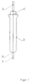
- Fig. 1
- eine Seitenansicht eines Temperaturfühlers mit der erfindungsgemäßen Knickschutzvorrichtung,
- Fig. 2
- eine Draufsicht auf das in Fig. 1 gezeigte Gerät,
- Fig. 3
- einen Schnitt längs der Linie III-III in Fig.2, und
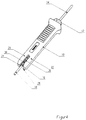
- Fig. 4
- eine Schrägansicht des Geräts von rechts hinten.
Claims (2)
- Knickschutzvorrichtung für ein elektrisches Kabel, das aus einem Ende des Handgriffs eines handbetätigbaren elektrischen Geräts herausgeführt ist, wobei ein Abschnitt des Kabels von einer elastischen Knickschutzmanschette umfaßt ist, dadurch gekennzeichnet, daß das kabelseitige Ende (16) des Handgriffs (10) als Gabel mit zwei flachen Zinken (20,22) ausgebildet ist, deren Breitseiten (24,26) parallel zueinander angeordnet sind und zwischen denen der die Knickschutzmanschette (30) aufweisende Kabelabschnitt (32) in unbelastetem Zustand angeordnet ist.
- Knickschutzvorrichtung nach Anspruch 1, wobei das elektrische Gerät als Temperaturfühler ausgebildet ist, dadurch gekennzeichnet, daß aus dem dem Kabelende (16) entgegengesetzten Ende (12) des Handgriffs (10) eine langgestreckte starre Sonde (14) vorsteht.
Applications Claiming Priority (2)
| Application Number | Priority Date | Filing Date | Title |
|---|---|---|---|
| DE9413224U | 1994-08-16 | ||
| DE9413224U DE9413224U1 (de) | 1994-08-16 | 1994-08-16 | Knickschutzvorrichtung für ein elektrisches Kabel |
Publications (3)
| Publication Number | Publication Date |
|---|---|
| EP0701301A2 EP0701301A2 (de) | 1996-03-13 |
| EP0701301A3 EP0701301A3 (de) | 1996-04-03 |
| EP0701301B1 true EP0701301B1 (de) | 1999-01-20 |
Family
ID=6912467
Family Applications (1)
| Application Number | Title | Priority Date | Filing Date |
|---|---|---|---|
| EP95112069A Expired - Lifetime EP0701301B1 (de) | 1994-08-16 | 1995-08-01 | Knickschutzvorrichtung für ein elektrisches Kabel |
Country Status (4)
| Country | Link |
|---|---|
| EP (1) | EP0701301B1 (de) |
| AT (1) | ATE176095T1 (de) |
| DE (2) | DE9413224U1 (de) |
| ES (1) | ES2127975T3 (de) |
Family Cites Families (3)
| Publication number | Priority date | Publication date | Assignee | Title |
|---|---|---|---|---|
| DE560829C (de) * | 1928-02-22 | 1932-10-07 | Rudolf Hase Dr | Nadelfoermiges Thermoelement zum Einstechen |
| GB958169A (en) * | 1962-07-03 | 1964-05-13 | Nuclear Power Plant Co Ltd | Improvements in and relating to thermocouple arrangements for nuclear reactor fuel elements |
| DE3518313C2 (de) * | 1985-05-22 | 1987-04-16 | Rowenta-Werke Gmbh, 6050 Offenbach | Kabeleinführung für Bügeleisen |
-
1994
- 1994-08-16 DE DE9413224U patent/DE9413224U1/de not_active Expired - Lifetime
-
1995
- 1995-08-01 AT AT95112069T patent/ATE176095T1/de not_active IP Right Cessation
- 1995-08-01 DE DE59504883T patent/DE59504883D1/de not_active Expired - Fee Related
- 1995-08-01 ES ES95112069T patent/ES2127975T3/es not_active Expired - Lifetime
- 1995-08-01 EP EP95112069A patent/EP0701301B1/de not_active Expired - Lifetime
Also Published As
| Publication number | Publication date |
|---|---|
| DE9413224U1 (de) | 1994-10-20 |
| DE59504883D1 (de) | 1999-03-04 |
| ES2127975T3 (es) | 1999-05-01 |
| EP0701301A2 (de) | 1996-03-13 |
| ATE176095T1 (de) | 1999-02-15 |
| EP0701301A3 (de) | 1996-04-03 |
Similar Documents
| Publication | Publication Date | Title |
|---|---|---|
| DE19538252C2 (de) | Struktur eines Griffes für motorgetriebene Werkzeuge | |
| DE10045498C2 (de) | Elektrische Reihenklemme | |
| EP0636349A1 (de) | Zahnbürste | |
| DE69502914T2 (de) | Verbessertes Handwerkzeug | |
| EP0988827A1 (de) | Anschlussvorrichtung für die intraatriale EKG-Ableitung | |
| WO2001042046A2 (de) | Kabeldurchführung | |
| DE1963137A1 (de) | Elektrische Steckverbindung | |
| EP0496972B1 (de) | Steckverbinder, insbesondere zur lösbaren Verbindung elektrischer Leiter | |
| DE60309808T2 (de) | Elastische Anschlussklemme | |
| EP0701301B1 (de) | Knickschutzvorrichtung für ein elektrisches Kabel | |
| EP0780923B1 (de) | Klemme zum Verbinden eines Leiterendes mit einem Kontakt | |
| DE19513170A1 (de) | Schutzkontaktstecker | |
| DE19630414A1 (de) | (Speicher) programmierbare Steuerung | |
| DE102020119685B3 (de) | Überzugskörper für Schiebeeinrichtungen | |
| DE3524384C2 (de) | Isolierhülle zum Aufnehmen einer elektrischen Anschlußklemme | |
| DE2907967B1 (de) | Elektrischer Stecker | |
| DE3018479C2 (de) | Öffnerkontaktanordnung | |
| DE3222597C2 (de) | ||
| DE10039963C2 (de) | Schneidklemmeinrichtung | |
| EP0824769B1 (de) | Steckdose für ein elektrogerät | |
| DE7828797U1 (de) | Handmikrofon | |
| DE202006008497U1 (de) | Positionierung von teleskopischem Werkzeug | |
| DE19646435C2 (de) | Elektrotechnisches Gerät | |
| DE3201177C2 (de) | Vorrichtung zur staubdichten Unterbringung von Verbindern von Lichtwellenleiterfasern | |
| DE29711589U1 (de) | Bediengerät für numerische Steuerungen |
Legal Events
| Date | Code | Title | Description |
|---|---|---|---|
| PUAI | Public reference made under article 153(3) epc to a published international application that has entered the european phase |
Free format text: ORIGINAL CODE: 0009012 |
|
| PUAL | Search report despatched |
Free format text: ORIGINAL CODE: 0009013 |
|
| AK | Designated contracting states |
Kind code of ref document: A2 Designated state(s): AT BE CH DE ES FR GB IT LI NL |
|
| AK | Designated contracting states |
Kind code of ref document: A3 Designated state(s): AT BE CH DE ES FR GB IT LI NL |
|
| 17P | Request for examination filed |
Effective date: 19960507 |
|
| GRAG | Despatch of communication of intention to grant |
Free format text: ORIGINAL CODE: EPIDOS AGRA |
|
| GRAG | Despatch of communication of intention to grant |
Free format text: ORIGINAL CODE: EPIDOS AGRA |
|
| GRAH | Despatch of communication of intention to grant a patent |
Free format text: ORIGINAL CODE: EPIDOS IGRA |
|
| 17Q | First examination report despatched |
Effective date: 19980618 |
|
| GRAH | Despatch of communication of intention to grant a patent |
Free format text: ORIGINAL CODE: EPIDOS IGRA |
|
| GRAA | (expected) grant |
Free format text: ORIGINAL CODE: 0009210 |
|
| AK | Designated contracting states |
Kind code of ref document: B1 Designated state(s): AT BE CH DE ES FR GB IT LI NL |
|
| REF | Corresponds to: |
Ref document number: 176095 Country of ref document: AT Date of ref document: 19990215 Kind code of ref document: T |
|
| ITF | It: translation for a ep patent filed | ||
| REG | Reference to a national code |
Ref country code: CH Ref legal event code: NV Representative=s name: DIPL.-ING. ETH H. R. WERFFELI PATENTANWALT Ref country code: CH Ref legal event code: EP |
|
| GBT | Gb: translation of ep patent filed (gb section 77(6)(a)/1977) |
Effective date: 19990122 |
|
| REF | Corresponds to: |
Ref document number: 59504883 Country of ref document: DE Date of ref document: 19990304 |
|
| ET | Fr: translation filed | ||
| REG | Reference to a national code |
Ref country code: ES Ref legal event code: FG2A Ref document number: 2127975 Country of ref document: ES Kind code of ref document: T3 |
|
| PLBE | No opposition filed within time limit |
Free format text: ORIGINAL CODE: 0009261 |
|
| STAA | Information on the status of an ep patent application or granted ep patent |
Free format text: STATUS: NO OPPOSITION FILED WITHIN TIME LIMIT |
|
| 26N | No opposition filed | ||
| REG | Reference to a national code |
Ref country code: GB Ref legal event code: IF02 |
|
| PGFP | Annual fee paid to national office [announced via postgrant information from national office to epo] |
Ref country code: GB Payment date: 20030730 Year of fee payment: 9 |
|
| PGFP | Annual fee paid to national office [announced via postgrant information from national office to epo] |
Ref country code: NL Payment date: 20030818 Year of fee payment: 9 |
|
| PGFP | Annual fee paid to national office [announced via postgrant information from national office to epo] |
Ref country code: FR Payment date: 20030819 Year of fee payment: 9 |
|
| PGFP | Annual fee paid to national office [announced via postgrant information from national office to epo] |
Ref country code: ES Payment date: 20030821 Year of fee payment: 9 |
|
| PGFP | Annual fee paid to national office [announced via postgrant information from national office to epo] |
Ref country code: AT Payment date: 20030822 Year of fee payment: 9 |
|
| PGFP | Annual fee paid to national office [announced via postgrant information from national office to epo] |
Ref country code: CH Payment date: 20030826 Year of fee payment: 9 |
|
| PGFP | Annual fee paid to national office [announced via postgrant information from national office to epo] |
Ref country code: BE Payment date: 20030827 Year of fee payment: 9 |
|
| PGFP | Annual fee paid to national office [announced via postgrant information from national office to epo] |
Ref country code: DE Payment date: 20030912 Year of fee payment: 9 |
|
| PG25 | Lapsed in a contracting state [announced via postgrant information from national office to epo] |
Ref country code: GB Free format text: LAPSE BECAUSE OF NON-PAYMENT OF DUE FEES Effective date: 20040801 Ref country code: AT Free format text: LAPSE BECAUSE OF NON-PAYMENT OF DUE FEES Effective date: 20040801 |
|
| PG25 | Lapsed in a contracting state [announced via postgrant information from national office to epo] |
Ref country code: ES Free format text: LAPSE BECAUSE OF NON-PAYMENT OF DUE FEES Effective date: 20040802 |
|
| PG25 | Lapsed in a contracting state [announced via postgrant information from national office to epo] |
Ref country code: LI Free format text: LAPSE BECAUSE OF NON-PAYMENT OF DUE FEES Effective date: 20040831 Ref country code: CH Free format text: LAPSE BECAUSE OF NON-PAYMENT OF DUE FEES Effective date: 20040831 Ref country code: BE Free format text: LAPSE BECAUSE OF NON-PAYMENT OF DUE FEES Effective date: 20040831 |
|
| BERE | Be: lapsed |
Owner name: *TESTO G.M.B.H. & CO. Effective date: 20040831 |
|
| PG25 | Lapsed in a contracting state [announced via postgrant information from national office to epo] |
Ref country code: NL Free format text: LAPSE BECAUSE OF NON-PAYMENT OF DUE FEES Effective date: 20050301 Ref country code: DE Free format text: LAPSE BECAUSE OF NON-PAYMENT OF DUE FEES Effective date: 20050301 |
|
| GBPC | Gb: european patent ceased through non-payment of renewal fee |
Effective date: 20040801 |
|
| REG | Reference to a national code |
Ref country code: CH Ref legal event code: PL |
|
| PG25 | Lapsed in a contracting state [announced via postgrant information from national office to epo] |
Ref country code: FR Free format text: LAPSE BECAUSE OF NON-PAYMENT OF DUE FEES Effective date: 20050429 |
|
| NLV4 | Nl: lapsed or anulled due to non-payment of the annual fee |
Effective date: 20050301 |
|
| REG | Reference to a national code |
Ref country code: FR Ref legal event code: ST |
|
| PG25 | Lapsed in a contracting state [announced via postgrant information from national office to epo] |
Ref country code: IT Free format text: LAPSE BECAUSE OF NON-PAYMENT OF DUE FEES;WARNING: LAPSES OF ITALIAN PATENTS WITH EFFECTIVE DATE BEFORE 2007 MAY HAVE OCCURRED AT ANY TIME BEFORE 2007. THE CORRECT EFFECTIVE DATE MAY BE DIFFERENT FROM THE ONE RECORDED. Effective date: 20050801 |
|
| REG | Reference to a national code |
Ref country code: ES Ref legal event code: FD2A Effective date: 20040802 |
|
| BERE | Be: lapsed |
Owner name: *TESTO G.M.B.H. & CO. Effective date: 20040831 |