EP0701035B1 - Schloss für Gefängnistüren - Google Patents
Schloss für Gefängnistüren Download PDFInfo
- Publication number
- EP0701035B1 EP0701035B1 EP95113821A EP95113821A EP0701035B1 EP 0701035 B1 EP0701035 B1 EP 0701035B1 EP 95113821 A EP95113821 A EP 95113821A EP 95113821 A EP95113821 A EP 95113821A EP 0701035 B1 EP0701035 B1 EP 0701035B1
- Authority
- EP
- European Patent Office
- Prior art keywords
- bolt
- locking
- tumbler
- tumblers
- lock
- Prior art date
- Legal status (The legal status is an assumption and is not a legal conclusion. Google has not performed a legal analysis and makes no representation as to the accuracy of the status listed.)
- Expired - Lifetime
Links
- 230000008878 coupling Effects 0.000 claims abstract description 31
- 238000010168 coupling process Methods 0.000 claims abstract description 31
- 238000005859 coupling reaction Methods 0.000 claims abstract description 31
- 230000008859 change Effects 0.000 claims description 13
- 230000007935 neutral effect Effects 0.000 claims description 3
- 230000002441 reversible effect Effects 0.000 abstract 2
- 238000000926 separation method Methods 0.000 description 5
- 230000000903 blocking effect Effects 0.000 description 2
- 208000003443 Unconsciousness Diseases 0.000 description 1
- 230000008901 benefit Effects 0.000 description 1
- 238000006243 chemical reaction Methods 0.000 description 1
- 230000003993 interaction Effects 0.000 description 1
- 230000007246 mechanism Effects 0.000 description 1
Images

Classifications
-
- E—FIXED CONSTRUCTIONS
- E05—LOCKS; KEYS; WINDOW OR DOOR FITTINGS; SAFES
- E05B—LOCKS; ACCESSORIES THEREFOR; HANDCUFFS
- E05B35/00—Locks for use with special keys or a plurality of keys ; keys therefor
- E05B35/08—Locks for use with special keys or a plurality of keys ; keys therefor operable by a plurality of keys
- E05B35/083—Locks for use with special keys or a plurality of keys ; keys therefor operable by a plurality of keys with changeable combination
-
- E—FIXED CONSTRUCTIONS
- E05—LOCKS; KEYS; WINDOW OR DOOR FITTINGS; SAFES
- E05B—LOCKS; ACCESSORIES THEREFOR; HANDCUFFS
- E05B65/00—Locks or fastenings for special use
- E05B65/0017—Jail locks
Definitions
- the invention relates to a lock for prison doors with at least one Tumbler set, each made directly by the key bit actuable locking tumblers guided on the lock plate and locking tumblers, which can be raised and in the longitudinal direction of the bolt slidably guided and one of a coupling piece and one Coupling channel, existing coupling can be released to change the locking mechanism are connected to the locking tumblers, both in the excluded as well as in the retracted position of the bolt Locking tumblers are transferred to their neutral starting position and the Locking tumblers with a dead bolt on a holding pin of the Lock plates are specified.
- Locks of the type described above intended for prison doors are known for example from DE-AS 1 156 674. You have through that Configurability of the lock a high security against unauthorized opening of the prison doors.
- a disadvantage of the known locks is the fact that when withdrawn Bolt unintentionally changed the lock can be excluded if the bolt is locked with another key is because a change of locking takes place automatically when the withdrawn Bolt with another key is excluded. Because not recognizable with which closure the bolt was excluded can This can cause difficulties when the latch turns back into its retracted position Position should be transferred.
- the invention is based on the features described above To further develop locks for prison doors in such a way that only a targeted changeover the closure can be done so that the unconscious Change of lock resulting from the use of other keys Disadvantages are avoided.
- the solution to this problem by the invention is characterized in that that between each guard locking and locking guard locking one Changeover tumbler is arranged, which can be raised on the bolt shaft and can be coupled via the clutch with the locking tumbler and the a toothing is releasably connected to the locking device, which in turn can be raised on a support plate, which during normal operation of the Bolt non-positively connected to the bolt by at least one spring, but to change the closure against the force of the spring when pulling back of the excluded bolt can be set in the end position is the one that corresponds to the excluded bar.
- This inventive design one intended for prison doors
- the lock has the advantage that the lock can only be changed can, if the bolt on a door opened with the right key open door excluded and by fixing the support plate in front of the Withdrawal of the bolt prepared a conversion of the locking system becomes.
- the support plate which is a separation between Locking and switching tumblers results in the assignment between these two tumblers, so that subsequently by use another key the change of the lock of the lock can be done.
- the training according to the invention does not only make handling easier of the prison door lock improved, but also increased security achieved because an unintentional, possibly manipulated change of the Closure is prevented.
- the Support plate in its front end position by a changeover rod, which at open door adjustable against the force of a return spring in the lock is arranged.
- this is Changeover bar adjustable in height on guide pins of the lock plate and can be coupled to the support plate via a coupling hook.
- the changeover rod in both Secure end positions of the bolt against lifting by means of stops. According to the invention this can be done in that the change-over rod when retracted Bolt by means of a stop pin which interacts with the support plate and in the case of a completely excluded bar by creating one Stop edge on the bolt shaft is secured against lifting. The latter Fuse is released when the bolt is slightly withdrawn to enable actuation of the changeover rod.
- the one is non-positive Connection of the support plate with the spring effecting the bolt between the bolt shaft and the support plate.
- the invention proposes two, each consisting of locking, To order existing guard locking sets for changeover and locking tumblers, whose switch tumblers are arranged to be liftable on the same support plate. This doubling of the tumblers will further increase the Security achieved.
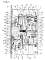
- a lock plate 1 can be seen in each case, on the front, angled edge a faceplate 2 is attached. Through an opening in the faceplate 2, the protrudes at the front end of a locking shaft 3 trained bolt head 3 through.
- the bolt shaft 3 is over Elongated holes 3b slidably mounted on guide pins 1a, which on Lock plate 1 are attached. Not to attach to the drawing Lock cover shown, the lock plate 1 continues with threaded bushings 1b provided.
- the actuation of the bolt consisting of bolt shaft 3 and bolt head 3a is carried out by a key S, which is shown in dashed lines in FIGS. 1 to 5 is and attached to a key pin 1g arranged on the lock plate 1 becomes.
- Key S acts on two sets of locking tumblers 4 that over Elongated holes 4a on the same guide pins 1a as the locking shaft 3 are adjustable in height on the lock plate 1.
- the locking tumblers 4 are for interaction with the key bit of the key S each executed with a tumbler channel. In the area of this tumbler channel are arranged on the lock plate 1 two stop pins 1c, which twist of key S in the wrong direction of rotation.
- Each locking tumbler 4 acts with a via a coupling channel 4b
- Coupling piece 5a of a changeover tumbler 5, which has elongated holes 5b are vertically adjustable on bearing pins 3c of the locking shaft 3.
- Each change guard locking acts via a toothing on the front 5 together with teeth of a locking tumbler 6.
- the blocking tumblers 6 are by means of elongated holes 6a on guide pins 7a of a support plate 7 adjustable in height, which is below the locking shaft 3 between this Bolt shaft 3 and the lock plate 1 is arranged.
- the in the slots 6a of the locking tumblers 6 engaging guide pins 7a of the support plate 7 pass through elongated holes 3d, which are formed on the locking shaft 3.
- the locking tumblers 6 are formed with an incision 6b with which they can be fixed on a bearing mandrel 1d. These bearing pins 1d are on the Lock plate 1 arranged.
- a tension spring 8 is arranged between the support plate 7 and the locking shaft 3.
- This tension spring designed as a helical spring in the exemplary embodiment 8 is at one end on a spring mandrel 3e of the locking shaft 3 and arranged with the other end on a spring mandrel 7b of the support plate 7.
- This spring mandrel 7b of the support plate 7 engages through an elongated hole 3f in the locking shaft 3 through.
- the support plate 7 is at one end with a coupling hook 7c provided that cooperates with a coupling hook 9a of a changeover rod 9.
- This switch rod 9 is on slots 9b on guide pins 1e of the lock plate 1 guided vertically and by a return spring 9c charged.
- the changeover rod 9 is formed with a stop edge 9e cooperates with a front corner of the locking shaft 3 (see Fig. 2 and 5).
- FIG. 1f Tumbler springs 10, which the closing tumblers 4 in the direction of Load the key pin 1g.
- a holder 11 can be seen, the on a bearing mandrel 1h of the lock plate 1 pivoted and is loaded by a leg spring 11a.
- This holder 11 is opposed the force of the leg spring 11a by at least one locking tumbler 4 in Swiveled clockwise and engages in each with a locking lug 11b two end positions of the locking shaft 3 in recesses provided for this purpose to prevent the bolt 3 from being unwantedly moved out of the respective To prevent end position.
Landscapes
- Lock And Its Accessories (AREA)
Description
- Fig. 1
- eine ohne Schloßdecke gezeichnete Draufsicht auf das Schloß mit zurückgezogenem Riegel;
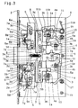
- Fig. 2
- eine der Fig. 1 entsprechende Draufsicht mit ausgeschlossenem Riegel;
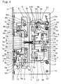
- Fig. 3
- eine weitere Draufsicht, bei der der Riegel aus seiner ausgeschlossenen Stellung nach Fig. 2 leicht zurückgezogen ist;
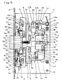
- Fig. 4
- eine Draufsicht auf das Schloß nach den Fig. 1 bis 3 in einer Stellung, in der der Riegel nach Betätigen der Umstellstange zurückgezogen wurde und damit eine Trennung der Sperr- und Umstellzuhaltungen sowie ein Festlegen der Sperrzuhaltungen auf dem Haltestift erfolgt ist, und
- Fig. 5
- eine weitere Draufsicht auf das Schloß, wobei sich der Riegel in der ausgeschlossenen Stellung befindet, das Ausschließen jedoch mit einer anderen Schließung erfolgte.
- S
- Schlüssel
- 1
- Schloßblech
- 1a
- Führungsstift
- 1b
- Gewindebüchse
- 1c
- Anschlagstift
- 1d
- Lagerdorn
- 1e
- Führungsstift 9f Stift
- 1f
- Federdorn
- 1g
- Schlüsseldorn
- 1h
- Lagerdorn
- 2
- Stulp
- 2a
- Öffnung
- 3
- Riegelschaft
- 3a
- Riegelkopf
- 3b
- Langloch
- 3c
- Lagerstift
- 3d
- Langloch
- 3e
- Federdorn
- 3f
- Langloch
- 4
- Schließzuhaltung
- 4a
- Langloch
- 4b
- Kupplungskanal
- 5
- Umstellzuhaltung
- 5a
- Kupplungsstück
- 5b
- Langloch
- 6
- Sperrzuhaltung
- 6a
- Langloch
- 6b
- Einschnitt
- 7
- Tragplatte
- 7a
- Führungsstift
- 7b
- Federdorn
- 7c
- Kupplungshaken
- 7d
- Verlängerung
- 8
- Zugfeder
- 9
- Umstellstange
- 9a
- Kupplungshaken
- 9b
- Langloch
- 9c
- Rückzugsfeder
- 9d
- Anschlagdorn
- 9e
- Anschlagkante
- 9f
- Stift
- 10
- Zuhaltungsfeder
- 11
- Festhalter
- 11a
- Schenkelfeder
- 11b
- Sperrnase
Claims (8)
- Schloß für Gefängnistüren mit mindestens einem Zuhaltungssatz, der jeweils aus unmittelbar durch den Schlüsselbart betätigbaren, auf dem Schloßblech anhebbar geführten Schließzuhaltungen und Sperrzuhaltungen besteht, die anhebbar und in Längsrichtung des Riegels verschiebbar geführt und über eine aus einem Kupplungsstück und einem Kupplungskanal bestehende Kupplung zur Umstellung der Schließung lösbar mit den Schließzuhaltungen verbunden sind, wobei sowohl in der ausgeschlossenen als auch in der zurückgezogenen Stellung des Riegels die Schließzuhaltungen in ihre neutrale Ausgangsstellung überführt sind und die Sperrzuhaltungen bei ausgeschlossenem Riegel auf einem Haltestift des Schloßbleches festlegt sind,
dadurch gekennzeichnet,
daß zwischen jeder Schließzuhaltung (4) und Sperrzuhaltung (6) eine Umstellzuhaltung (5) angeordnet ist, die anhebbar auf dem Riegelschaft (3) geführt und über die Kupplung (4b,5a) mit der Schließzuhaltung (4) kuppelbar ist und die über eine Verzahnung lösbar mit der Sperrzuhaltung (6) verbunden ist, die ihrerseits anhebbar auf einer Tragplatte (7) geführt ist, welche bei normaler Betätigung des Riegels durch mindestens eine Feder (8) kraftschlüssig mit dem Riegelschaft (3) verbunden, aber zur Umstellung der Schließung entgegen der Kraft der Feder (8) beim Zurückziehen des ausgeschlossenen Riegels in der Endstellung festlegbar ist die dem ausgeschlossenen Stellung des Riegels entspricht. - Schloß nach Anspruch 1, dadurch gekennzeichnet, daß die Festlegung der Tragplatte (7) in ihrer vorderen Endstellung durch eine Umstellstange (9) erfolgt, die bei geöffneter Tür entgegen der Kraft einer Rückzugsfeder (9c) verstellbar im Schloß angeordnet ist.
- Schloß nach Anspruch 2, dadurch gekennzeichnet, daß die Umstellstange (9) höhenverstellbar auf Führungsstiften (1e) des Schloßbleches (1) geführt und über einen Kupplungshaken (9a) mit der Tragplatte (7) kuppelbar ist.
- Schloß nach Anspruch 2 oder 3, dadurch gekennzeichnet, daß die Umstellstange (9) in beiden Endstellungen des Riegels durch Anschläge (9d,9e) gegen ein Anheben gesichert ist.
- Schloß nach Anspruch 4, dadurch gekennzeichnet, daß die Umstellstangen (9) bei zurückgezogenem Riegel durch einen mit der Tragplatte (7) zusammenwirkenden Anschlagdorn (9d) gegen Anheben gesichert ist.
- Schloß nach Anspruch 4, dadurch gekennzeichnet, daß die Umstellstange (9) bei vollständig ausgeschlossenem Riegel durch Anlage einer Anschlagkante (9e) am Riegelschaft (3) gegen Anheben gesichert ist.
- Schloß nach mindestens einem der Ansprüche 1 bis 6, dadurch gekennzeichnet, daß die eine kraftschlüssige Verbindung der Tragplatte (7) mit dem Riegelschaft (3) bewirkende Feder (8) zwischen dem Riegelschaft (3) und der Tragplatte (7) angeordnet ist.
- Schloß nach mindestens einem der Ansprüche 1 bis 7, dadurch gekennzeichnet, daß zwei jeweils aus Schließ-, Umstell- und Sperrzuhaltungen (4,5,6) bestehende Zuhaltungssätze angeordnet sind, deren Umstellzuhaltungen (5) auf derselben Tragplatte (7) anhebbar angeordnet sind.
Applications Claiming Priority (2)
| Application Number | Priority Date | Filing Date | Title |
|---|---|---|---|
| DE4431923A DE4431923C1 (de) | 1994-09-08 | 1994-09-08 | Schloß für Gefängnistüren |
| DE4431923 | 1994-09-08 |
Publications (2)
| Publication Number | Publication Date |
|---|---|
| EP0701035A1 EP0701035A1 (de) | 1996-03-13 |
| EP0701035B1 true EP0701035B1 (de) | 1998-08-05 |
Family
ID=6527666
Family Applications (1)
| Application Number | Title | Priority Date | Filing Date |
|---|---|---|---|
| EP95113821A Expired - Lifetime EP0701035B1 (de) | 1994-09-08 | 1995-09-02 | Schloss für Gefängnistüren |
Country Status (3)
| Country | Link |
|---|---|
| EP (1) | EP0701035B1 (de) |
| AT (1) | ATE169365T1 (de) |
| DE (1) | DE4431923C1 (de) |
Families Citing this family (2)
| Publication number | Priority date | Publication date | Assignee | Title |
|---|---|---|---|---|
| DE19738244C2 (de) * | 1997-09-02 | 2002-04-11 | Steinbach & Vollmann | Schloß für Sicherheitstüren |
| DE19826869C1 (de) * | 1998-06-17 | 2000-01-13 | Steinbach & Vollmann | Schloß für Hochsicherheitstüren |
Family Cites Families (5)
| Publication number | Priority date | Publication date | Assignee | Title |
|---|---|---|---|---|
| DE389133C (de) * | 1921-07-06 | 1924-01-26 | Hans Hartlaub | Auf verschiedene Schluesselbaerte einstellbares Sicherheitsschloss |
| US1901229A (en) * | 1929-05-18 | 1933-03-14 | Sargent & Greenleaf | Multiple key lock |
| US1826595A (en) * | 1930-07-30 | 1931-10-06 | Mosler Lock Company | Interchangeable key lock |
| DE1156674B (de) * | 1960-04-25 | 1963-10-31 | Steinbach & Vollmann | Schliesseinrichtung mit umstellbaren Zuhaltungen |
| DE1703277A1 (de) * | 1968-04-26 | 1972-05-10 | Kromer Kg Theodor | Schloss mit auf verschiedene Schluessel umstellbaren Zuhaltungen |
-
1994
- 1994-09-08 DE DE4431923A patent/DE4431923C1/de not_active Expired - Fee Related
-
1995
- 1995-09-02 EP EP95113821A patent/EP0701035B1/de not_active Expired - Lifetime
- 1995-09-02 AT AT95113821T patent/ATE169365T1/de not_active IP Right Cessation
Also Published As
| Publication number | Publication date |
|---|---|
| DE4431923C1 (de) | 1995-10-26 |
| EP0701035A1 (de) | 1996-03-13 |
| ATE169365T1 (de) | 1998-08-15 |
Similar Documents
| Publication | Publication Date | Title |
|---|---|---|
| DE3447748C2 (de) | ||
| EP0204944B1 (de) | Fallen-Panikschloss, insbesondere für Rohrrahmentüren | |
| EP0653535B1 (de) | Schloss | |
| DE3931101C2 (de) | ||
| EP0701035B1 (de) | Schloss für Gefängnistüren | |
| DE19826869C1 (de) | Schloß für Hochsicherheitstüren | |
| DE4215856C1 (de) | Schließzylinder, unter Verwendung solcher Schließzylinder gebildete Schließanlage, Schlüssel für den Schließzylinder und Verfahren zur Herstellung einer Schließzylinder-Schlüssel-Kombination | |
| DE4431925C2 (de) | Schloß für Gefängnistüren | |
| EP0701034B1 (de) | Schloss für Gefängnistüren | |
| EP0298292B1 (de) | Türschloss mit verschiebbarem Riegel und Falle | |
| DE19738244C2 (de) | Schloß für Sicherheitstüren | |
| DE3042611C2 (de) | ||
| DE3513265C2 (de) | Schloß für Justizvollzugsanstalten | |
| DE2850598A1 (de) | Verschluss mit tagriegel | |
| CH671603A5 (de) | ||
| DE806211C (de) | Drueckerschloss | |
| DE2350347C2 (de) | Türschloß | |
| DE19738242C2 (de) | Schloß für Sicherheitstüren | |
| DE9321038U1 (de) | Selbstverriegelndes Sicherheitstürschloß | |
| DE631968C (de) | Durchsteckschloss mit zwei Schliesstouren und mit Sperrung des Mieterschluessels gegen Herausziehen bei eingezogenem Riegel | |
| DE3226404A1 (de) | Verriegelungsvorrichtung fuer eine kraftfahrzeugtuer | |
| DE824608C (de) | Als Riegelfallenschloss ausgebildetes Einsteckschloss | |
| DE668616C (de) | Schloss, insbesondere mit zylindrischem Gehaeuse | |
| DE336864C (de) | Sicherheitsschloss | |
| CH565931A5 (en) | Locking mechanism for doors of safes, etc. - bolt bar locking simultaneously actuates all locks |
Legal Events
| Date | Code | Title | Description |
|---|---|---|---|
| PUAI | Public reference made under article 153(3) epc to a published international application that has entered the european phase |
Free format text: ORIGINAL CODE: 0009012 |
|
| AK | Designated contracting states |
Kind code of ref document: A1 Designated state(s): AT FR GB NL SE |
|
| 17P | Request for examination filed |
Effective date: 19960115 |
|
| GRAG | Despatch of communication of intention to grant |
Free format text: ORIGINAL CODE: EPIDOS AGRA |
|
| GRAG | Despatch of communication of intention to grant |
Free format text: ORIGINAL CODE: EPIDOS AGRA |
|
| GRAH | Despatch of communication of intention to grant a patent |
Free format text: ORIGINAL CODE: EPIDOS IGRA |
|
| 17Q | First examination report despatched |
Effective date: 19980114 |
|
| GRAH | Despatch of communication of intention to grant a patent |
Free format text: ORIGINAL CODE: EPIDOS IGRA |
|
| GRAA | (expected) grant |
Free format text: ORIGINAL CODE: 0009210 |
|
| AK | Designated contracting states |
Kind code of ref document: B1 Designated state(s): AT FR GB NL SE |
|
| PG25 | Lapsed in a contracting state [announced via postgrant information from national office to epo] |
Ref country code: NL Free format text: LAPSE BECAUSE OF FAILURE TO SUBMIT A TRANSLATION OF THE DESCRIPTION OR TO PAY THE FEE WITHIN THE PRESCRIBED TIME-LIMIT Effective date: 19980805 Ref country code: GB Free format text: LAPSE BECAUSE OF FAILURE TO SUBMIT A TRANSLATION OF THE DESCRIPTION OR TO PAY THE FEE WITHIN THE PRESCRIBED TIME-LIMIT Effective date: 19980805 Ref country code: FR Free format text: LAPSE BECAUSE OF FAILURE TO SUBMIT A TRANSLATION OF THE DESCRIPTION OR TO PAY THE FEE WITHIN THE PRESCRIBED TIME-LIMIT Effective date: 19980805 |
|
| REF | Corresponds to: |
Ref document number: 169365 Country of ref document: AT Date of ref document: 19980815 Kind code of ref document: T |
|
| PG25 | Lapsed in a contracting state [announced via postgrant information from national office to epo] |
Ref country code: SE Free format text: LAPSE BECAUSE OF FAILURE TO SUBMIT A TRANSLATION OF THE DESCRIPTION OR TO PAY THE FEE WITHIN THE PRESCRIBED TIME-LIMIT Effective date: 19981105 |
|
| EN | Fr: translation not filed | ||
| NLV1 | Nl: lapsed or annulled due to failure to fulfill the requirements of art. 29p and 29m of the patents act | ||
| GBV | Gb: ep patent (uk) treated as always having been void in accordance with gb section 77(7)/1977 [no translation filed] |
Effective date: 19980805 |
|
| PLBE | No opposition filed within time limit |
Free format text: ORIGINAL CODE: 0009261 |
|
| STAA | Information on the status of an ep patent application or granted ep patent |
Free format text: STATUS: NO OPPOSITION FILED WITHIN TIME LIMIT |
|
| 26N | No opposition filed | ||
| PGFP | Annual fee paid to national office [announced via postgrant information from national office to epo] |
Ref country code: AT Payment date: 20010824 Year of fee payment: 7 |
|
| PG25 | Lapsed in a contracting state [announced via postgrant information from national office to epo] |
Ref country code: AT Free format text: LAPSE BECAUSE OF NON-PAYMENT OF DUE FEES Effective date: 20020902 |