EP0699511A2 - Fahrzeugmischer für fliessfähige Medien, wie Beton - Google Patents
Fahrzeugmischer für fliessfähige Medien, wie Beton Download PDFInfo
- Publication number
- EP0699511A2 EP0699511A2 EP95113597A EP95113597A EP0699511A2 EP 0699511 A2 EP0699511 A2 EP 0699511A2 EP 95113597 A EP95113597 A EP 95113597A EP 95113597 A EP95113597 A EP 95113597A EP 0699511 A2 EP0699511 A2 EP 0699511A2
- Authority
- EP
- European Patent Office
- Prior art keywords
- drum
- tube
- mixing drum
- mixer according
- vehicle
- Prior art date
- Legal status (The legal status is an assumption and is not a legal conclusion. Google has not performed a legal analysis and makes no representation as to the accuracy of the status listed.)
- Granted
Links
- 230000009969 flowable effect Effects 0.000 title claims description 3
- XLYOFNOQVPJJNP-UHFFFAOYSA-N water Substances O XLYOFNOQVPJJNP-UHFFFAOYSA-N 0.000 claims abstract description 13
- 230000002265 prevention Effects 0.000 claims description 2
- 239000007858 starting material Substances 0.000 claims 1
- 239000000203 mixture Substances 0.000 abstract description 3
- 238000007599 discharging Methods 0.000 abstract 1
- 238000005406 washing Methods 0.000 abstract 1
- 238000007789 sealing Methods 0.000 description 3
- 238000012423 maintenance Methods 0.000 description 2
- 244000089486 Phragmites australis subsp australis Species 0.000 description 1
- 230000002093 peripheral effect Effects 0.000 description 1
- 230000003068 static effect Effects 0.000 description 1
- 239000000725 suspension Substances 0.000 description 1
Images
Classifications
-
- B—PERFORMING OPERATIONS; TRANSPORTING
- B28—WORKING CEMENT, CLAY, OR STONE
- B28C—PREPARING CLAY; PRODUCING MIXTURES CONTAINING CLAY OR CEMENTITIOUS MATERIAL, e.g. PLASTER
- B28C5/00—Apparatus or methods for producing mixtures of cement with other substances, e.g. slurries, mortars, porous or fibrous compositions
- B28C5/42—Apparatus specially adapted for being mounted on vehicles with provision for mixing during transport
- B28C5/4203—Details; Accessories
- B28C5/4234—Charge or discharge systems therefor
- B28C5/4237—Charging, e.g. hoppers
-
- B—PERFORMING OPERATIONS; TRANSPORTING
- B28—WORKING CEMENT, CLAY, OR STONE
- B28C—PREPARING CLAY; PRODUCING MIXTURES CONTAINING CLAY OR CEMENTITIOUS MATERIAL, e.g. PLASTER
- B28C5/00—Apparatus or methods for producing mixtures of cement with other substances, e.g. slurries, mortars, porous or fibrous compositions
- B28C5/42—Apparatus specially adapted for being mounted on vehicles with provision for mixing during transport
- B28C5/4203—Details; Accessories
- B28C5/4231—Proportioning or supplying water
-
- B—PERFORMING OPERATIONS; TRANSPORTING
- B28—WORKING CEMENT, CLAY, OR STONE
- B28C—PREPARING CLAY; PRODUCING MIXTURES CONTAINING CLAY OR CEMENTITIOUS MATERIAL, e.g. PLASTER
- B28C5/00—Apparatus or methods for producing mixtures of cement with other substances, e.g. slurries, mortars, porous or fibrous compositions
- B28C5/42—Apparatus specially adapted for being mounted on vehicles with provision for mixing during transport
- B28C5/4203—Details; Accessories
- B28C5/4262—Closures; Sealing mechanisms
-
- B—PERFORMING OPERATIONS; TRANSPORTING
- B28—WORKING CEMENT, CLAY, OR STONE
- B28C—PREPARING CLAY; PRODUCING MIXTURES CONTAINING CLAY OR CEMENTITIOUS MATERIAL, e.g. PLASTER
- B28C5/00—Apparatus or methods for producing mixtures of cement with other substances, e.g. slurries, mortars, porous or fibrous compositions
- B28C5/42—Apparatus specially adapted for being mounted on vehicles with provision for mixing during transport
- B28C5/4203—Details; Accessories
- B28C5/4265—Mounting means for drums; Support frames
Definitions
- the invention relates to a vehicle mixer for flowable media, such as concrete, with the features of the preamble of claim 1.
- Such a vehicle mixer is known from US-A-2,303902.
- the closure element consists of a pipe socket of the feed funnel and projects axially into the drum mouth.
- the central tube is only provided in the rear end area of the drum and is attached to radial arms of the drum.
- a sleeve passes through the feed hopper and is slidably mounted on the tube.
- the short pipe attached on one side cannot support the feed hopper without vibration. Vibrations of the pipe lead to leaks in the area of the ring seal between the drum mouth and the closure element.
- the permanently installed pipe is an obstacle for maintenance work inside the mixing drum.
- the object of the invention is to improve the storage of the closure element of the mixing drum in order to complete the seal.
- the assembly which includes the closure element and the tube, preferably also the feed hopper, can be removed as a whole from the drum and retracted, which simplifies maintenance work.
- the at least two rotary bearings in the drum are preferably arranged near the drum ends, thus ensuring low-vibration support of the closure element with the feed hopper on the drum even with large static and dynamic loads. This is for one Uniform, good sealing of the closure element on the drum mouth is crucial.
- a particularly advantageous development of the invention is to be seen in the fact that the tube is given an additional function thanks to a pressurized water connection and a number of water outlet nozzles in the interior of the drum.
- the recipe-related mixing water quantity can be metered into the dry concrete mix very effectively.
- the water is distributed more evenly and quickly. It is preferred that the majority of the nozzles jet obliquely and vertically upwards. Therefore, the majority of the nozzles are preferably located in the upper half of the tube.
- Another embodiment of the invention is that removable wear sleeves are arranged on the tube in the area of its bearings in the mixing drum. In conjunction with the pressurized water feed into the pipe, this wear protection can now be easily cleaned and lubricated with leakage water from the pipe. This extends the lifespan.
- the nozzles in the tube are preferably self-sealing and equipped with an exchangeable wear protection.
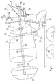
- a mixing drum 16 On a vehicle frame 10 there is a bearing block 12 with rollers 14, on which a mixing drum 16 is rotatably mounted via a running ring 18 in the rear area of the mixing drum.
- the mixing drum 16 has a rear drum mouth 20 which is delimited by an annular flange 22.
- the mixing drum 16 At the opposite front end, the mixing drum 16 is closed and has a central pin, not shown, which is used for storage and for the rotary drive.
- the mixing drum is state of the art.
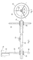
- a coaxial tube 24 is arranged in the interior of the mixing drum and is mounted so as to be relatively rotatable and axially displaceable by means of a front bearing 26 and a rear bearing 28.
- the two bearings 26, 28 are held by means of star-shaped arms 30 on the or the peripheral spirals 32 of the mixing drum 16.
- the bearing shells of the bearings 26, 28 have a larger inner diameter than the outer diameter of the tube 24.
- wear sleeves 34 which are exchangeably fastened on the tube 24.
- the pipe 24 protrudes from the drum mouth 20 and carries at its end a rigidly fastened closure element 36 which comprises an annular wall 38 with an annular seal 40 and a feed funnel 42 which is penetrated by the tube 24.
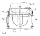
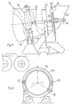
- a U-bracket 44 is attached to the tube end and is welded to the side walls of the feed funnel 42. From the bracket 12, two support arms 41 extend upwards, on one of which a torque support 46 is fastened, which is designed in such a way that it prevents the feed hopper 42 from pivoting about the drum axis, without, however, transmitting relative movements between the drum and undercarriage to the hopper 42 . On a transversely extending yoke 48 of the bracket 44, two pressure medium cylinders 50, 52 engage, which lie in an axial plane of the drum 16 and have their counter bearing according to FIG. 4 on the support arms 41 or according to FIG.
- a bearing yoke 54 which is relative is rotatably mounted on the rim 18 of the mixing drum 16 and is secured against rotation with the drum 16 by means of a rotation prevention device 56.
- the bearing yoke 54 has a plurality of rollers, which are supported on the running surface of the running ring 18, and rollers lying at right angles thereto, which touch the running rim on both end faces.
- the bearing yoke 54 thus forms an abutment for the actuating cylinders 50, 52, which thus do not exert any forces on the closure element due to deformations of the vehicle frame, which results in a perfect sealing of the drum even while the vehicle is traveling.
- the structural unit consisting of closure element 36, feed funnel 42 and tube 24 is axially adjusted and moves from the open position shown in FIG. 1 to a closed position in which the ring seal 40 is located on the ring flange 22 Mixing drum 16 creates.
- the annular wall 38 of the closure element 36 has a forward-facing nozzle 58, which is smaller in diameter than the ring seal 40. This connecting piece 58 engages in the interior of the drum 16 and protects the ring seal 40.
- the tube 24 protrudes from the funnel 42 and has a pressurized water connection 62 at the projecting end, to which a pressurized water hose can be connected.
- the tube 24 is provided along its entire length in the area of the mixing drum 16 with axially spaced outlet nozzles 64, most of the nozzles being arranged in the upper half of the tube 24 and pointing upwards. Mixing water can thus be metered into the dry concrete mixture evenly distributed over the entire length of the drum via the pipe 24.
Landscapes
- Engineering & Computer Science (AREA)
- Mechanical Engineering (AREA)
- Structural Engineering (AREA)
- Preparation Of Clay, And Manufacture Of Mixtures Containing Clay Or Cement (AREA)
Abstract
Description
- Die Erfindung betrifft einen Fahrzeugmischer für fließfähige Medien, wie Beton, mit den Merkmalen des Oberbegriffes von Patentanspruch 1.
- Ein derartiger Fahrzeugmischer ist aus der US-A-2,303902 bekannt. Das Verschlußelement besteht aus einem Rohrstutzen des Aufgabetrichters und ragt in den Trommelmund axial hinein. Das zentrale Rohr ist nur im hinteren Endbereich der Trommel vorgesehen und an Radialarmen der Trommel befestigt. Den Aufgabetrichter durchsetzt eine Hülse, mit der der Aufgabetrichter auf dem Rohr verschiebbar gelagert ist. Das einseitig befestigte kurze Rohr kann den Aufgabetrichter nicht schwingungsfrei abstützen. Schwingungen des Rohres führen zu Undichtigkeiten im Bereich der Ringdichtung zwischen Trommelmund und Verschlußelement. Das fest eingebaute Rohr bildet für Wartungsarbeiten im Inneren der Mischtrommel ein Hindernis.
- Aufgabe der Erfindung ist es, die Lagerung des Verschlußelementes der Mischtrommel zu verbessern, um die Abdichtung zu vervollkommen.
- Diese Aufgabe wird erfindungsgemäß durch die Merkmale des Patentanspruches 1 gelöst.
- Die Baueinheit, die das Verschlußelement und das Rohr, vorzugsweise auch den Aufgabetrichter umfaßt, kann als Ganzes von der Trommel abgezogen und wieder eingefahren werden, wodurch Wartungsarbeiten erleichtert werden. Die mindestens zwei Drehlager in der Trommel sind vorzugsweise nahe den Trommelenden angeordnet, gewährleisten also auch bei großen statischen und dynamischen Belastungen eine schwingungsarme Abstützung des Verschlußelements mit Aufgabetrichter an der Trommel. Dies ist für eine gleichmäßige, gute Abdichtung des Verschlußelementes am Trommelmund entscheidend.
- Eine besonders vorteilhafte Weiterbildung der Erfindung ist darin zu sehen, daß das Rohr dank eines Druckwasseranschlusses und einer Anzahl Wasseraustrittsdüsen im Innenraum der Trommel eine zusätzliche Funktion erhält. Die rezeptbezogene Anmachwassermenge kann sehr wirksam in die trockene Betonmischung eindosiert werden. Die Verteilung des Wassers erfolgt gleichmäßiger und schneller. Dabei wird vorgezogen, daß die Mehrzahl der Düsen schräg und vertikal aufwärts abstrahlen. Deswegen ist die Mehrzahl der Düsen vorzugsweise in der oberen Hälfte des Rohres angeordnet.
- Eine weitere Ausgestaltung der Erfindung besteht darin, daß auf dem Rohr im Bereich seiner Lagerungen in der Mischtrommel abnehmbare Verschleißhülsen angeordnet sind. In Verbindung mit der Druckwassereinspeisung in das Rohr kann nun sehr einfach dieser Verschleißschutz mit Leckwasser aus dem Rohr gereinigt und geschmiert werden. Die Lebensdauer wird dadurch verlängert. Die Düsen im Rohr sind vorzugsweise selbstverschließend und mit einem auswechselbaren Verschleißschutz ausgestattet.
- Anhand der Zeichnung, die ein Ausführungsbeispiel der Erfindung darstellt, wird diese näher beschrieben.
- Es zeigt:
- FIG. 1
- eine Seitenansicht einer auf einem Fahrzeugrahmen gelagerten Mischtrommel mit verstellbarer Verschlußeinrichtung,
- FIG. 2
- einen Axialschnitt durch die Lagerung des zentralen Rohres innerhalb der Mischtrommel,
- FIG. 3
- eine Stirnansicht der Rohrlagerung in der Mischtrommel,
- FIG. 4
- eine Draufsicht auf den Heckbereich der Mischtrommel mit Darstellung einer Stelleinrichtung zum Verschieben des Verschlußelementes,
- FIG. 5
- eine Seitenansicht des Heckbereiches der Mischtrommel, mit einer abgewandelten Aufhängung der Stellzylinder für das verschiebbare Verschlußelement, und
- FIG. 6
- eine heckseitige Ansicht der Ausführungsform gemäß Figur 5.
- Auf einem Fahrzeugrahmen 10 befindet sich ein Lagerbock 12 mit Rollen 14, auf denen eine Mischtrommel 16 über einen Laufkranz 18 im Heckbereich der Mischtrommel drehbar gelagert ist. Die Mischtrommel 16 weist einen heckseitigen Trommelmund 20 auf, der von einem Ringflansch 22 begrenzt wird. Am gegenüberliegenden vorderseitigen Ende ist die Mischtrommel 16 geschlossen und hat einen nicht dargestellten zentralen Zapfen, der zur Lagerung und zum Drehantrieb dient. Die Mischtrommel ist insoweit Stand der Technik.
- Im Inneren der Mischtrommel ist ein koaxiales Rohr 24 angeordnet, welches mittels eines vorderen Lagers 26 und eines hinteren Lagers 28 relativ drehbar und axial verschiebbar gelagert ist. Die beiden Lager 26, 28 sind mittels sternförmiger Arme 30 an der oder den Umfangsspiralen 32 der Mischtrommel 16 gehaltert. Die Lagerschalen der Lager 26, 28 haben einen größeren Innendurchmesser, als er dem Außendurchmesser des Rohres 24 entspricht. Im Ringraum befinden sich Verschleißhülsen 34, die auswechselbar auf dem Rohr 24 befestigt sind. Das Rohr 24 ragt aus dem Trommelmund 20 heraus und trägt an seinem Ende ein starr befestigtes Verschlußelement 36, das eine Ringwand 38 mit Ringdichtung 40 sowie einen Aufgabetrichter 42 umfaßt, der vom Rohr 24 durchsetzt wird. Am Rohrende ist ein U-Bügel 44 befestigt, der an den Seitenwänden des Aufgabetrichters 42 angeschweißt ist. Vom Lagerbock 12 erstrecken sich zwei Tragarme 41 nach oben, an deren einem eine Drehmomentabstützung 46 befestigt ist, welche so ausgelegt ist, daß sie ein Verschwenken des Aufgabetrichters 42 um die Trommelachse verhindert, ohne jedoch Relativbewegungen zwischen Trommel und Fahrwerk auf den Trichter 42 zu übertragen. An einem sich quer erstreckenden Joch 48 des Bügels 44 greifen zwei Druckmittelzylinder 50, 52 an, die in einer Axialebene der Trommel 16 liegen und ihr Gegenlager gemäß Fig. 4 an den Tragarmen 41 oder gemäß Fig. 5 an einem Lagerjoch 54 haben, welches relativ drehbar auf dem Laufkranz 18 der Mischtrommel 16 gelagert und mittels einer Drehverhinderungseinrichtung 56 gegen ein Mitdrehen mit der Trommel 16 gesichert ist. Das Lagerjoch 54 weist mehrere Rollen auf, die sich auf der Lauffläche des Laufkranzes 18 abstützen, sowie dazu rechtwinklig liegende Rollen, die den Laufkranz an beiden Stirnseiten berühren. Das Lagerjoch 54 bildet somit ein Widerlager für die Stellzylinder 50, 52, die somit keine Kräfte aufgrund von Verformungen des Fahrzeugrahmens auf das Verschlußelement ausüben, woraus eine vollkommene Abdichtung der Trommel auch während der Fahrt des Fahrzeuges resultiert.
- Durch Betätigen der beiden vorzugsweise pneumatisch betriebenen Stellzylinder 50, 52 wird die aus Verschlußelement 36, Aufgabetrichter 42 und Rohr 24 bestehende Baueinheit axial verstellt und gelangt aus der in Fig. 1 gezeigten Offenstellung in eine Schließstellung, in welcher die Ringdichtung 40 sich am Ringflansch 22 der Mischtrommel 16 anlegt. Die Ringwand 38 des Verschlußelementes 36 hat einen nach vorn weisenden Stutzen 58, der auf kleinerem Durchmesser liegt als die Ringdichtung 40. Dieser Stutzen 58 greift in das Innere der Trommel 16 ein und schützt die Ringdichtung 40.
- Das Rohr 24 ragt aus dem Trichter 42 heraus und weist am herausragenden Ende einen Druckwasseranschluß 62 auf, an den ein Druckwasserschlauch anschließbar ist. Das Rohr 24 ist über seine ganze Länge im Bereich der Mischtrommel 16 mit axial beabstandeten Auslaßdüsen 64 versehen, wobei die meisten Düsen in der oberen Hälfte des Rohres 24 angeordnet und aufwärts gerichtet sind. Über das Rohr 24 kann somit Anmachwasser über die ganze Trommellänge gleichmäßig verteilt in die trockene Betonmischung eindosiert werden.
Claims (8)
- Fahrzeugmischer für fließfähige Medien, wie Beton, mit einer Mischtrommel (16), die einen heckseitigen Trommelmund (22) und an ihrem Außenumfang einen Laufkranz (18) aufweist, der von Rollen (14) eines Aufbaus (12) des Fahrzeugrahmens drehbar abgestützt ist und deren Trommelmund (22) durch ein Verschlußelement (36) mit Aufgabetrichter (42) absperrbar ist, wobei das Verschlußelement (36) mittels eines, den Trommelmund koaxial durchsetzenden und von der Mischtrommel (16) abgestützten Rohres (24) zwischen einer, den Trommelmund (22) mittels einer Ringdichtung (40) abschließenden Schließstellung und einer Offenstellung verschiebbar angeordnet, gegen Mitdrehen durch einen Drehverhinderungsschutz (46) gesichert und durch eine Stelleinrichtung (50, 52) verstellbar ist, dadurch gekennzeichnet, daß das Rohr (24) mit dem Verschlußelement (36) eine Baueinheit bildet und daR das Rohr (24) sich über wenigstens den größten Teil der Länge der Mischtrommel (16) erstreckt, die mindestens zwei koaxiale Dreh- und Schiebelager (26, 28) für das Rohr (24) aufweist.
- Fahrzeugmischer nach Anspruch 1, dadurch gekennzeichnet, daß der Aufgabetrichter (42) Bestandteil der aus dem Verschlußelement (36) und dem Rohr (24) bestehenden Baueinheit ist.
- Fahrzeugmischer nach Anspruch 1 oder 2, dadurch gekennzeichnet, daß auf dem Rohr (24) im Bereich seiner Lagerungen (26, 28) in der Mischtrommel (16) abnehmbare Verschleißhülsen (34) angeordnet sind.
- Fahrzeugmischer nach einem der Ansprüche 1-3, dadurch gekennzeichnet, daß die Stelleinrichtung zwei beidseitig des Aufgabetrichters (42) an der Baueinheit (24, 36) angeordnete Druckmittelzylinder (50, 52) aufweist, die an einem Lagerjoch (54) befestigt sind, das an dem Laufkranz (18) der Mischtrommel (16) relativ drehbar abgestützt ist.
- Fahrzeugmischer nach einem der Ansprüche 1-4, dadurch gekennzeichnet, daß die Ringdichtung (40) außerhalb eines, in die Trommel (16) hineinragenden Verschleißschutzstutzens (58) der Baueinheit (24, 36, 42) angeordnet ist.
- Fahrzeugmischer nach einem der Ansprüche 1-6, dadurch gekennzeichnet, daß das Rohr (24) außerhalb der Mischtrommel (16) einen Druckwasseranschluß (62) und im Bereich der Trommel (16) mehrere über die Länge der Mischtrommel (16) verteilte Austrittsdüsen (64) aufweist.
- Fahrzeugmischer nach Anspruch 6, dadurch gekennzeichnet, daß wenigstens einige der Austrittsdüsen (64) aufwärts gerichtet sind.
- Fahrzeugmischer nach Anspruch 6 oder 7, dadurch gekennzeichnet, daß die.Auslaßdüsen (64) Verschlußmittel aufweisen, die die Anlaßdüsen (64) im drucklosen Zustand des Rohres (24) selbsttätig schließen und bei Druckwasserzufuhr die Düsen (64) öffnen.
Applications Claiming Priority (2)
| Application Number | Priority Date | Filing Date | Title |
|---|---|---|---|
| DE4431501A DE4431501B4 (de) | 1994-09-03 | 1994-09-03 | Fahrzeugmischer für fließfähige Medien, wie Beton |
| DE4431501 | 1994-09-03 |
Publications (3)
| Publication Number | Publication Date |
|---|---|
| EP0699511A2 true EP0699511A2 (de) | 1996-03-06 |
| EP0699511A3 EP0699511A3 (de) | 1996-04-17 |
| EP0699511B1 EP0699511B1 (de) | 2001-07-04 |
Family
ID=6527405
Family Applications (1)
| Application Number | Title | Priority Date | Filing Date |
|---|---|---|---|
| EP95113597A Expired - Lifetime EP0699511B1 (de) | 1994-09-03 | 1995-08-30 | Fahrzeugmischer für fliessfähige Medien, wie Beton |
Country Status (4)
| Country | Link |
|---|---|
| US (1) | US5513911A (de) |
| EP (1) | EP0699511B1 (de) |
| CZ (1) | CZ287408B6 (de) |
| DE (2) | DE4431501B4 (de) |
Cited By (5)
| Publication number | Priority date | Publication date | Assignee | Title |
|---|---|---|---|---|
| RU2212338C2 (ru) * | 2001-12-06 | 2003-09-20 | Общество с ограниченной ответственностью "Фирма ЭСКОРТ" | Установка смесительная осреднительная |
| CN101856989A (zh) * | 2010-05-24 | 2010-10-13 | 烟台盛利达工程技术有限公司 | 回转密封新技术及搅拌筒水平布置的混凝土搅拌运输车 |
| CN107344401A (zh) * | 2017-08-29 | 2017-11-14 | 烟台盛利达工程技术有限公司 | 中空轴回转密封的混凝土搅拌运输车 |
| CN107457900A (zh) * | 2017-09-18 | 2017-12-12 | 张家港沙工科技服务有限公司 | 一种密封防漏式搅拌机输料装置 |
| WO2020248763A1 (zh) * | 2019-06-12 | 2020-12-17 | 烟台盛利达工程技术有限公司 | 一种螺旋压紧的离合式回转密封机构 |
Families Citing this family (13)
| Publication number | Priority date | Publication date | Assignee | Title |
|---|---|---|---|---|
| US5718508A (en) * | 1996-10-29 | 1998-02-17 | Haltec Corporation | Self-cleaning mixer for cement slurry |
| US6418948B1 (en) * | 1998-10-30 | 2002-07-16 | Thomas G. Harmon | Apparatus and method for removing concrete from interior surfaces of a concrete mixing drum |
| GB2377391A (en) * | 2001-07-10 | 2003-01-15 | Tarmac Ltd | Pressurised transferral of liquid to the inside of a vehicular concrete mixer |
| DE102004003373A1 (de) | 2004-01-22 | 2005-08-11 | Stetter Gmbh | Fahrmischer für fließfähige Medien, insbesondere Beton |
| DE202009004188U1 (de) * | 2009-03-25 | 2010-08-12 | Liebherr-Mischtechnik Gmbh | Fahrmischer |
| DE202009004187U1 (de) * | 2009-03-25 | 2010-08-12 | Liebherr-Mischtechnik Gmbh | Fahrmischer |
| US9194092B2 (en) * | 2010-01-26 | 2015-11-24 | Mark Kline | Mechanism for automated mixing of liquid solutions and granular materials |
| CN103223695B (zh) * | 2013-05-14 | 2015-05-27 | 十九冶成都建设有限公司 | 二次流化剂添加系统 |
| DE102014006774A1 (de) | 2014-05-08 | 2015-11-12 | Beiqi Foton Motor Co., Ltd. | Fahrmischer für fließfähige Medien, insbesondere Beton |
| CN104108136A (zh) * | 2014-06-29 | 2014-10-22 | 广西科亮路桥机械有限公司 | 一种混凝土搅拌运输车的自动向轴心双托轮机构 |
| CN109624087B (zh) * | 2019-01-29 | 2023-12-29 | 烟台盛利达工程技术有限公司 | 一体式回转密封系统 |
| US11786945B2 (en) | 2020-03-12 | 2023-10-17 | Caterpillar Paving Products Inc. | Cleaning nozzles of a machine |
| CN111283874A (zh) * | 2020-04-10 | 2020-06-16 | 烟台盛利达工程技术有限公司 | 一种摆转式回转密封系统 |
Citations (6)
| Publication number | Priority date | Publication date | Assignee | Title |
|---|---|---|---|---|
| US2265752A (en) | 1940-01-11 | 1941-12-09 | Chain Belt Co | Apparatus for charging concrete mixers |
| US2303902A (en) | 1941-04-17 | 1942-12-01 | Chain Belt Co | Mixing concrete |
| US2348682A (en) | 1942-04-10 | 1944-05-09 | Jaeger Machine Co | Door structure for mixers |
| GB587488A (en) | 1944-09-27 | 1947-04-28 | Chain Belt Co | Concrete mixer |
| GB593703A (en) | 1944-08-22 | 1947-10-23 | Jaeger Machine Co | Improvements in or relating to mixing machines |
| US2439250A (en) | 1943-12-27 | 1948-04-06 | Chain Belt Co | Transit concrete mixer |
Family Cites Families (11)
| Publication number | Priority date | Publication date | Assignee | Title |
|---|---|---|---|---|
| DE581116C (de) * | 1931-08-28 | 1933-07-21 | Jaeger Machine Co | Fahrbare Betonmischmaschine |
| US2338820A (en) * | 1940-01-13 | 1944-01-11 | T L Smith Co | Concrete mixer |
| US2280513A (en) * | 1941-04-21 | 1942-04-21 | Jaeger Machine Co | Door structure for mixers |
| US2362435A (en) * | 1942-01-28 | 1944-11-07 | Chain Belt Co | Concrete mixer |
| US2454940A (en) * | 1946-07-27 | 1948-11-30 | T L Smith Co | Seal for chutes of concrete mixers |
| DE3106347C2 (de) * | 1981-02-20 | 1986-09-25 | Reinhard 5461 Windhagen Wirtgen | Vorrichtung zur Herstellung von auftragfähigem erwärmtem Belagmaterial zum Beschichten von Straßendecken |
| US4506983A (en) * | 1982-02-01 | 1985-03-26 | Marr Leonard D | Bulk material storage and mixing apparatus |
| US4478514A (en) * | 1983-02-22 | 1984-10-23 | Ingrid Hudelmaier | Vibrating concrete mixer |
| DE3732231A1 (de) * | 1987-09-24 | 1989-04-13 | Hudelmaier Ingrid | Verfahren zum bestimmen der konsistenz von beton und zugehoeriger betonmischer |
| EP0374681A1 (de) * | 1988-12-17 | 1990-06-27 | Stetter Gmbh | Fahrzeugmischer |
| EP0642900B1 (de) * | 1993-05-05 | 1996-07-17 | Stetter Gmbh | Fahrzeugmischer für fliessfähige Medien, wie Beton |
-
1994
- 1994-09-03 DE DE4431501A patent/DE4431501B4/de not_active Expired - Fee Related
-
1995
- 1995-08-29 US US08/520,706 patent/US5513911A/en not_active Expired - Lifetime
- 1995-08-30 EP EP95113597A patent/EP0699511B1/de not_active Expired - Lifetime
- 1995-08-30 DE DE59509375T patent/DE59509375D1/de not_active Expired - Lifetime
- 1995-08-30 CZ CZ19952225A patent/CZ287408B6/cs not_active IP Right Cessation
Patent Citations (6)
| Publication number | Priority date | Publication date | Assignee | Title |
|---|---|---|---|---|
| US2265752A (en) | 1940-01-11 | 1941-12-09 | Chain Belt Co | Apparatus for charging concrete mixers |
| US2303902A (en) | 1941-04-17 | 1942-12-01 | Chain Belt Co | Mixing concrete |
| US2348682A (en) | 1942-04-10 | 1944-05-09 | Jaeger Machine Co | Door structure for mixers |
| US2439250A (en) | 1943-12-27 | 1948-04-06 | Chain Belt Co | Transit concrete mixer |
| GB593703A (en) | 1944-08-22 | 1947-10-23 | Jaeger Machine Co | Improvements in or relating to mixing machines |
| GB587488A (en) | 1944-09-27 | 1947-04-28 | Chain Belt Co | Concrete mixer |
Cited By (5)
| Publication number | Priority date | Publication date | Assignee | Title |
|---|---|---|---|---|
| RU2212338C2 (ru) * | 2001-12-06 | 2003-09-20 | Общество с ограниченной ответственностью "Фирма ЭСКОРТ" | Установка смесительная осреднительная |
| CN101856989A (zh) * | 2010-05-24 | 2010-10-13 | 烟台盛利达工程技术有限公司 | 回转密封新技术及搅拌筒水平布置的混凝土搅拌运输车 |
| CN107344401A (zh) * | 2017-08-29 | 2017-11-14 | 烟台盛利达工程技术有限公司 | 中空轴回转密封的混凝土搅拌运输车 |
| CN107457900A (zh) * | 2017-09-18 | 2017-12-12 | 张家港沙工科技服务有限公司 | 一种密封防漏式搅拌机输料装置 |
| WO2020248763A1 (zh) * | 2019-06-12 | 2020-12-17 | 烟台盛利达工程技术有限公司 | 一种螺旋压紧的离合式回转密封机构 |
Also Published As
| Publication number | Publication date |
|---|---|
| DE59509375D1 (de) | 2001-08-09 |
| DE4431501B4 (de) | 2004-09-16 |
| US5513911A (en) | 1996-05-07 |
| CZ222595A3 (en) | 1996-03-13 |
| EP0699511B1 (de) | 2001-07-04 |
| EP0699511A3 (de) | 1996-04-17 |
| CZ287408B6 (en) | 2000-11-15 |
| DE4431501A1 (de) | 1996-03-07 |
Similar Documents
| Publication | Publication Date | Title |
|---|---|---|
| EP0699511A2 (de) | Fahrzeugmischer für fliessfähige Medien, wie Beton | |
| EP1055450A2 (de) | Rührwerk | |
| DE3044636C2 (de) | Trommelmühle für autogene oder halbautogene Mahlung | |
| DE3107966C2 (de) | Vorrichtung zum Entleeren eines aufrecht angeordneten Schüttgut-Rundsilos | |
| CH633074A5 (en) | Rock-drilling apparatus | |
| DE4211855A1 (de) | Vorrichtung zum Verladen von Schüttgut | |
| EP1724031B1 (de) | Vorrichtung zur Innenreinigung eines Silos | |
| EP0066755A1 (de) | Schlauchführungseinrichtung für eine Betonspritzanlage | |
| DE102009020409A1 (de) | Rotordüse | |
| DE2240751C3 (de) | Rührwerksmühle | |
| EP0492313B1 (de) | Vorrichtung zum Dosieren von Schüttgut | |
| DE2829631B2 (de) | Abstützvorrichtung, insbesondere für Betonpumpen | |
| DE19854704C1 (de) | Halte- und Reinigungsvorrichtung für zylindrische Filter | |
| WO2008006232A1 (de) | Reinigungswalze | |
| DE3740898A1 (de) | Mahlvorrichtung | |
| DE29621940U1 (de) | Reinigungsvorrichtung für einen Mischer, vorzugsweise Ringtellermischer | |
| DE3523472A1 (de) | Verladevorrichtung fuer fliessfaehige gueter | |
| CH654510A5 (en) | Abrasive-blasting machine | |
| DE4220035A1 (de) | Austragvorrichtung für Rundsilos | |
| DE1632143A1 (de) | Tuellenkopf fuer Wurstfuellmaschinen mit mehreren Tuellen | |
| DE3026033A1 (de) | Transportbetonmischer | |
| DE19938435C2 (de) | Reinigungsvorrichtung | |
| DE19637562C2 (de) | Dosiervorrichtung für Gülle | |
| DE3128113C2 (de) | Verstellbare Bandübergabe zur Verwendung im untertägigen Grubenbetrieb, mit einer um 360 Grad um einen Mittelpunkt stufenlos drehbaren Schurre | |
| EP0494166B1 (de) | Zuführvorrichtung für die dämpfungsflüssigkeit in führungsrohren bei mehrspindel-drehmaschinen und dergleichen |
Legal Events
| Date | Code | Title | Description |
|---|---|---|---|
| PUAI | Public reference made under article 153(3) epc to a published international application that has entered the european phase |
Free format text: ORIGINAL CODE: 0009012 |
|
| PUAL | Search report despatched |
Free format text: ORIGINAL CODE: 0009013 |
|
| AK | Designated contracting states |
Kind code of ref document: A2 Designated state(s): DE FR IT NL |
|
| AK | Designated contracting states |
Kind code of ref document: A3 Designated state(s): DE FR IT NL |
|
| 17P | Request for examination filed |
Effective date: 19961012 |
|
| 17Q | First examination report despatched |
Effective date: 20000307 |
|
| GRAG | Despatch of communication of intention to grant |
Free format text: ORIGINAL CODE: EPIDOS AGRA |
|
| GRAG | Despatch of communication of intention to grant |
Free format text: ORIGINAL CODE: EPIDOS AGRA |
|
| GRAH | Despatch of communication of intention to grant a patent |
Free format text: ORIGINAL CODE: EPIDOS IGRA |
|
| GRAH | Despatch of communication of intention to grant a patent |
Free format text: ORIGINAL CODE: EPIDOS IGRA |
|
| GRAA | (expected) grant |
Free format text: ORIGINAL CODE: 0009210 |
|
| AK | Designated contracting states |
Kind code of ref document: B1 Designated state(s): DE FR IT NL |
|
| ITF | It: translation for a ep patent filed | ||
| REF | Corresponds to: |
Ref document number: 59509375 Country of ref document: DE Date of ref document: 20010809 |
|
| ET | Fr: translation filed | ||
| PLBE | No opposition filed within time limit |
Free format text: ORIGINAL CODE: 0009261 |
|
| STAA | Information on the status of an ep patent application or granted ep patent |
Free format text: STATUS: NO OPPOSITION FILED WITHIN TIME LIMIT |
|
| 26N | No opposition filed | ||
| PGFP | Annual fee paid to national office [announced via postgrant information from national office to epo] |
Ref country code: NL Payment date: 20100823 Year of fee payment: 16 |
|
| PGFP | Annual fee paid to national office [announced via postgrant information from national office to epo] |
Ref country code: IT Payment date: 20100825 Year of fee payment: 16 Ref country code: FR Payment date: 20100901 Year of fee payment: 16 |
|
| PGFP | Annual fee paid to national office [announced via postgrant information from national office to epo] |
Ref country code: DE Payment date: 20101012 Year of fee payment: 16 |
|
| REG | Reference to a national code |
Ref country code: NL Ref legal event code: V1 Effective date: 20120301 |
|
| REG | Reference to a national code |
Ref country code: FR Ref legal event code: ST Effective date: 20120430 |
|
| PG25 | Lapsed in a contracting state [announced via postgrant information from national office to epo] |
Ref country code: IT Free format text: LAPSE BECAUSE OF NON-PAYMENT OF DUE FEES Effective date: 20110830 Ref country code: NL Free format text: LAPSE BECAUSE OF NON-PAYMENT OF DUE FEES Effective date: 20120301 |
|
| REG | Reference to a national code |
Ref country code: DE Ref legal event code: R119 Ref document number: 59509375 Country of ref document: DE Effective date: 20120301 |
|
| PG25 | Lapsed in a contracting state [announced via postgrant information from national office to epo] |
Ref country code: FR Free format text: LAPSE BECAUSE OF NON-PAYMENT OF DUE FEES Effective date: 20110831 |
|
| PG25 | Lapsed in a contracting state [announced via postgrant information from national office to epo] |
Ref country code: DE Free format text: LAPSE BECAUSE OF NON-PAYMENT OF DUE FEES Effective date: 20120301 |