EP0685032B1 - Procede et installation de ventilation de reservoir a essence - Google Patents
Procede et installation de ventilation de reservoir a essence Download PDFInfo
- Publication number
- EP0685032B1 EP0685032B1 EP95903255A EP95903255A EP0685032B1 EP 0685032 B1 EP0685032 B1 EP 0685032B1 EP 95903255 A EP95903255 A EP 95903255A EP 95903255 A EP95903255 A EP 95903255A EP 0685032 B1 EP0685032 B1 EP 0685032B1
- Authority
- EP
- European Patent Office
- Prior art keywords
- valve
- bypass
- tank
- adsorption filter
- air
- Prior art date
- Legal status (The legal status is an assumption and is not a legal conclusion. Google has not performed a legal analysis and makes no representation as to the accuracy of the status listed.)
- Expired - Lifetime
Links
Images


Classifications
-
- F—MECHANICAL ENGINEERING; LIGHTING; HEATING; WEAPONS; BLASTING
- F02—COMBUSTION ENGINES; HOT-GAS OR COMBUSTION-PRODUCT ENGINE PLANTS
- F02M—SUPPLYING COMBUSTION ENGINES IN GENERAL WITH COMBUSTIBLE MIXTURES OR CONSTITUENTS THEREOF
- F02M25/00—Engine-pertinent apparatus for adding non-fuel substances or small quantities of secondary fuel to combustion-air, main fuel or fuel-air mixture
- F02M25/08—Engine-pertinent apparatus for adding non-fuel substances or small quantities of secondary fuel to combustion-air, main fuel or fuel-air mixture adding fuel vapours drawn from engine fuel reservoir
- F02M25/0836—Arrangement of valves controlling the admission of fuel vapour to an engine, e.g. valve being disposed between fuel tank or absorption canister and intake manifold
-
- F—MECHANICAL ENGINEERING; LIGHTING; HEATING; WEAPONS; BLASTING
- F02—COMBUSTION ENGINES; HOT-GAS OR COMBUSTION-PRODUCT ENGINE PLANTS
- F02M—SUPPLYING COMBUSTION ENGINES IN GENERAL WITH COMBUSTIBLE MIXTURES OR CONSTITUENTS THEREOF
- F02M25/00—Engine-pertinent apparatus for adding non-fuel substances or small quantities of secondary fuel to combustion-air, main fuel or fuel-air mixture
- F02M25/08—Engine-pertinent apparatus for adding non-fuel substances or small quantities of secondary fuel to combustion-air, main fuel or fuel-air mixture adding fuel vapours drawn from engine fuel reservoir
- F02M25/089—Layout of the fuel vapour installation
Definitions
- the invention relates to a method for venting a fuel tank of a motor vehicle with an internal combustion engine according to the preamble of claim 1 and a tank ventilation system for performing the method.
- the purge air flow which must include a significant amount of air for effective purging of the adsorption filter per unit of time, is a not insignificant leakage flow with respect to the metered amount of air sucked in via the intake manifold, which leads to a lambda error when the internal combustion engine is working.
- an additional amount of fuel is supplied to the intake manifold in the case of a strongly gassing tank via the purge air, which can impair the optimization of the operating conditions of the internal combustion engine.
- EP-A-0 451 313 Also known from EP-A-0 451 313 is a tank ventilation system in which a bypass branches off from the intake manifold downstream of an air measuring element via a non-return valve and guides all the air flowing through the bypass through an adsorption filter and a tank ventilation valve downstream of a throttle valve into the intake manifold .
- the invention has for its object to provide an improved method for venting a fuel tank of a motor vehicle or an improved tank ventilation system, with or with which an adverse effect on the regulated mixture composition for an internal combustion engine during the Flushing the adsorption filter is avoided.
- An important advantage of the method according to the invention is that the purge air flow enters the intake manifold as a measured leakage stream, since it is branched off from the measured air flow in the intake manifold or in the bypass thereof, so that the operating parameters set for the internal combustion engine are adversely affected by an additionally supplied one Purge air volume is avoided under all operating conditions.
- FIG. 1 shows an intake manifold 10 in which an air measuring element 13 of a known type, for example a flap air knife, a hot film sensor or the like, of a fuel injection system, not shown, is arranged upstream of a throttle valve 12 serving as a throttle element.
- the intake air quantity can also be measured with the aid of an intake manifold pressure measurement downstream of the throttle valve 12.
- a bypass 14 is parallel to the section of the intake manifold 10 provided with the throttle valve provided, in which an idle actuator 16 is arranged. Normally, ie in a conventional system, the bypass 14 or the bypass line leads downstream from the throttle valve 12 directly into the intake manifold, since the bypass with the throttle valve 12 closed has the sole task of acting behind the throttle valve 12 to the internal combustion engine (not shown). limit the amount of flowing air to the amount of air set by the idle actuator 16.
- a tank ventilation valve 18 (regeneration valve) is inserted into the bypass 14 behind the idle actuator 16 in the tank ventilation system according to FIG Position each intermediate position is controllable valve is formed.
- a flushing line 20 serving for flushing, which can be controlled via a shut-off valve 22, which also acts as a between a completely blocking position 20 of the flush line 20 and a position completely opening the line 20 Valve is formed, leads to an adsorption filter 24, which is designed in particular as an activated carbon filter.
- the adsorption filter 24 is connected to a fuel tank 28 via a connecting line 26.
- the adsorption filter 24 is for rinsing via the tank ventilation valve by means of a further line 30 18 connected to the downstream end of the bypass line or to the suction pipe 10. Finally, a further connection of the shut-off valve 22 is connected to the atmosphere via a ventilation opening 32.
- valve 2 relates in particular to an operating state in which the two valves 18, 22 assume their rest position, their valve elements 18a, 22a being in the position shown in FIG. 2 when the excitation winding 18b or 22b is de-energized, in which position they are due to the pretension are held by schematically indicated spring elements 18c and 22c.
- the tank ventilation valve 18 is fully open with respect to the bypass line 14, and the combustion air flows predetermined by the throttle valve 12 and the idle actuator 16 flow via the intake manifold 10 and the bypass 14.
- the tank 28 is connected to the opening 32 via the filter 24 and the valve 22 opened for the exhaust air from the tank, while the valve 22 also blocks the line 20 between the bypass 14 and the filter 24.
- the tank 28 is gassed, the fuel vapors are adsorbed in the filter 24 and the exhaust air is released into the atmosphere via the valve 22 and the opening 32.
- the proportion of fuel in the exhaust air depends on the effectiveness and the condition of the adsorption filter 24. In a corresponding manner, fresh air is drawn in from the atmosphere via the opening 32 when a negative pressure arises in the tank 28.
- valve elements 18a and 22a of the valves 18 and 22 are in an intermediate position shown in FIG. 3, which is usually brought about by means of a correspondingly controlled excitation of the excitation windings 18b and 22b of the valves 18 and 22 by means of a clocked feed current becomes.
- the shut-off valve 22 completely opens the line 20 to the adsorption filter 24 and completely blocks the connection to the ventilation opening 32.
- the tank ventilation valve 18, on the other hand, assumes a position in which the bypass 14 and the line 30 are each partially open.
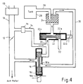
- valve 18 is brought into a further intermediate position in which the second line 30 coming from the filter 24 is throttled relatively strongly and the bypass 14 essentially is opened.
- a part of the air enriched with fuel vapors can be discharged into the environment after filtering in the adsorption filter 24, while another partial air flow, which can contain a certain amount of fuel vapors, can be discharged via the valve 18 with the Bypass flow merged and passed into the suction pipe 10.
- 3 to 5 can be checked as a function of signals which are generated with the aid of sensors which, for example, the internal pressure in the tank, the composition of the exhaust air at the opening 32 and Detect the fuel concentration in the second line 30 leading back to the valve 18, in order to ensure, if necessary in conjunction with other operating parameters, that the small amount of exhaust air, which is additionally introduced into the intake manifold in the operating state according to FIG. 5, as well as its fuel percentage, the set or do not affect the desired operating conditions for the internal combustion engine.
- sensors for example, the internal pressure in the tank, the composition of the exhaust air at the opening 32 and Detect the fuel concentration in the second line 30 leading back to the valve 18, in order to ensure, if necessary in conjunction with other operating parameters, that the small amount of exhaust air, which is additionally introduced into the intake manifold in the operating state according to FIG. 5, as well as its fuel percentage, the set or do not affect the desired operating conditions for the internal combustion engine.
- the method according to the invention or the tank ventilation system for its implementation opens up the possibility of generating a purge air flow for the regeneration of an adsorption filter without impairing the operating parameters for an internal combustion engine, only the Training of the valves which are usually present now to shut off the tank connection and to vent the tank as controllable valves is required.
- the use of these valves also enables a vacuum test or an overpressure test of the tank and the associated parts of the fuel supply system.
Abstract
Claims (6)
- Procédé de ventilation d'un réservoir de carburant d'un véhicule automobile équipé d'un moteur à combustion interne, comprenant une tubulure d'aspiration (10) avec un dispositif de mesure de l'air (13) et une dérivation (14) contournant un organe d'étranglement (12), munie notamment d'un organe de réglage de ralenti (16), le réservoir de carburant (28) étant ventilé à l'atmosphère à travers une conduite équipée d'un filtre par adsorption (24) et d'une vanne d'arrêt (22) comprise entre le filtre et une ouverture de ventilation (32), et le filtre par adsorption 24 est rincé avec de l'air de rinçage fourni à la tubulure d'aspiration (10) à travers une conduite contenant une soupape de ventilation de réservoir (18),
caractérisé en ce que
l'air de rinçage du filtre par adsorption (24) est dérivé du courant d'air traversant la dérivation (14). - Procédé selon la revendication 1,
caractérisé en ce que la quantité d'air de rinçage est étranglée lorsque le réservoir dégaze fortement. - Installation de ventilation d'un réservoir de carburant d'un véhicule automobile équipé d'un moteur à combustion interne, comprenant une tubulure d'aspiration (10) munie d'un dispositif de mesure de l'air (13) et d'une dérivation (14) comportant notamment un organe de réglage de ralenti (16), et contournant un volet d'étranglement (12), le réservoir de carburant (28) étant relié par une conduite équipée d'un filtre par adsorption (24) et d'une vanne d'arrêt (22) située entre celui-ci et l'ouverture de ventilation (32), pour être reliée à l'atmosphère, et un courant d'air de rinçage qui traverse le filtre par adsorption (24) est conduit vers la tubulure d'aspiration (10) par une conduite munie d'une soupape de ventilation de réservoir (18),
caractérisée en ce que
pour l'alimentation en flux d'air de rinçage vers le filtre par adsorption (24), il est prévu une conduite de rinçage (20) qui part de la dérivation (14). - Installation de ventilation de réservoir selon la revendication 3,
caractérisée en ce que
la conduite de rinçage (20) allant de la dérivation (14) vers le filtre par adsorption (24) est commandée par la soupape d'arrêt (22). - Installation de ventilation de réservoir selon la revendication 4,
caractérisée en ce que
la conduite de rinçage (20) commence entre un organe de réglage de ralenti (16) et une soupape de ventilation de réservoir (18) commandant également la conduite de dérivation (14). - Installation de ventilation de réservoir selon l'une des revendications 3 à 5,
caractérisée en ce que
la soupape d'arrêt (22) permet de fermer en même temps la conduite de rinçage (20) et la liaison vers l'orifice de ventilation (32).
Applications Claiming Priority (3)
| Application Number | Priority Date | Filing Date | Title |
|---|---|---|---|
| DE4343654 | 1993-12-21 | ||
| DE4343654A DE4343654A1 (de) | 1993-12-21 | 1993-12-21 | Verfahren und Anlage zur Tankentlüftung |
| PCT/DE1994/001531 WO1995017593A1 (fr) | 1993-12-21 | 1994-12-20 | Procede et installation de ventilation de reservoir a essence |
Publications (2)
| Publication Number | Publication Date |
|---|---|
| EP0685032A1 EP0685032A1 (fr) | 1995-12-06 |
| EP0685032B1 true EP0685032B1 (fr) | 1997-03-19 |
Family
ID=6505649
Family Applications (1)
| Application Number | Title | Priority Date | Filing Date |
|---|---|---|---|
| EP95903255A Expired - Lifetime EP0685032B1 (fr) | 1993-12-21 | 1994-12-20 | Procede et installation de ventilation de reservoir a essence |
Country Status (6)
| Country | Link |
|---|---|
| US (1) | US5533479A (fr) |
| EP (1) | EP0685032B1 (fr) |
| JP (1) | JPH08507119A (fr) |
| KR (1) | KR960701294A (fr) |
| DE (2) | DE4343654A1 (fr) |
| WO (1) | WO1995017593A1 (fr) |
Families Citing this family (11)
| Publication number | Priority date | Publication date | Assignee | Title |
|---|---|---|---|---|
| JPH0942080A (ja) * | 1995-07-26 | 1997-02-10 | Toyota Motor Corp | キャニスタ |
| JP3317121B2 (ja) * | 1996-01-25 | 2002-08-26 | 株式会社日立製作所 | エバポシステムおよびその診断方法 |
| US5857446A (en) * | 1996-07-01 | 1999-01-12 | Norton; Peter | Fuel vapor source |
| DE19645382C2 (de) * | 1996-11-04 | 1998-10-08 | Daimler Benz Ag | Tankentlüftungsanlage für ein Fahrzeug mit Verbrennungsmotor |
| US5878729A (en) * | 1998-05-06 | 1999-03-09 | General Motors Corporation | Air control valve assembly for fuel evaporative emission storage canister |
| DE10102604A1 (de) * | 2001-01-20 | 2002-07-25 | Mann & Hummel Filter | Ansaugsystem für eine Brennkraftmaschine und Verfahren zum Betreiben des Ansaugsystems |
| EP1729005A1 (fr) * | 2005-06-02 | 2006-12-06 | Delphi Technologies, Inc. | Système de commande des émissions de vapeur |
| DE102006002718B4 (de) * | 2006-01-19 | 2008-01-03 | Siemens Ag | Verfahren und Vorrichtung zum Betreiben einer Brennkraftmaschine |
| US7373930B1 (en) * | 2007-08-23 | 2008-05-20 | Chrysler Llc | Multi-port check-valve for an evaporative fuel emissions system in a turbocharged vehicle |
| CN102282352B (zh) * | 2009-02-02 | 2014-08-20 | 博格华纳公司 | 驱动装置 |
| JP5579554B2 (ja) * | 2010-09-22 | 2014-08-27 | 株式会社ケーヒン | 内燃機関の蒸発燃料制御装置 |
Family Cites Families (11)
| Publication number | Priority date | Publication date | Assignee | Title |
|---|---|---|---|---|
| JPH0726599B2 (ja) * | 1986-12-05 | 1995-03-29 | 日本電装株式会社 | 内燃機関用蒸発燃料制御装置 |
| US4926825A (en) * | 1987-12-07 | 1990-05-22 | Honda Giken Kogyo K.K. (Honda Motor Co., Ltd. In English) | Air-fuel ratio feedback control method for internal combustion engines |
| JP2721978B2 (ja) * | 1988-08-31 | 1998-03-04 | 富士重工業株式会社 | 空燃比学習制御装置 |
| US5005550A (en) * | 1989-12-19 | 1991-04-09 | Chrysler Corporation | Canister purge for turbo engine |
| DE59000761D1 (de) * | 1990-04-12 | 1993-02-25 | Siemens Ag | Tankentlueftungssystem. |
| JP2534462Y2 (ja) * | 1991-02-18 | 1997-04-30 | 富士重工業株式会社 | キャニスタ |
| JPH04311664A (ja) * | 1991-04-11 | 1992-11-04 | Toyota Motor Corp | 蒸発燃料回収装置 |
| US5275144A (en) * | 1991-08-12 | 1994-01-04 | General Motors Corporation | Evaporative emission system diagnostic |
| US5315980A (en) * | 1992-01-17 | 1994-05-31 | Toyota Jidosha Kabushiki Kaisha | Malfunction detection apparatus for detecting malfunction in evaporative fuel purge system |
| US5203300A (en) * | 1992-10-28 | 1993-04-20 | Ford Motor Company | Idle speed control system |
| JP2970280B2 (ja) * | 1993-02-05 | 1999-11-02 | トヨタ自動車株式会社 | 発電機駆動用エンジンの制御装置 |
-
1993
- 1993-12-21 DE DE4343654A patent/DE4343654A1/de not_active Withdrawn
-
1994
- 1994-12-20 JP JP7517093A patent/JPH08507119A/ja active Pending
- 1994-12-20 DE DE59402152T patent/DE59402152D1/de not_active Expired - Fee Related
- 1994-12-20 WO PCT/DE1994/001531 patent/WO1995017593A1/fr active IP Right Grant
- 1994-12-20 KR KR1019950703502A patent/KR960701294A/ko not_active Application Discontinuation
- 1994-12-20 US US08/507,261 patent/US5533479A/en not_active Expired - Fee Related
- 1994-12-20 EP EP95903255A patent/EP0685032B1/fr not_active Expired - Lifetime
Also Published As
| Publication number | Publication date |
|---|---|
| KR960701294A (ko) | 1996-02-24 |
| WO1995017593A1 (fr) | 1995-06-29 |
| DE4343654A1 (de) | 1995-06-22 |
| JPH08507119A (ja) | 1996-07-30 |
| US5533479A (en) | 1996-07-09 |
| EP0685032A1 (fr) | 1995-12-06 |
| DE59402152D1 (de) | 1997-04-24 |
Similar Documents
| Publication | Publication Date | Title |
|---|---|---|
| DE102011084539B3 (de) | Turbolader mit einer Venturidüse zur Entlüftung eines Aktivkohlefilters | |
| DE19608292C2 (de) | Kraftstoffdampfrückhaltesystem für einen Verbrennungsmotor | |
| DE102006054117B4 (de) | Im Teil- und Volllastbetrieb gesteuerte Kurbelgehäuse-Belüftung einer Brennkraftmaschine | |
| EP0685032B1 (fr) | Procede et installation de ventilation de reservoir a essence | |
| DE4229110C1 (de) | Vorrichtung zum vorübergehenden Speichern und dosierten Einspeisen von im Freiraum einer Tankanlage befindlichen flüchtigen Kraftstoffbestandteilen in das Ansaugrohr einer Verbrennungskraftmaschine | |
| DE4139946C1 (fr) | ||
| DE2521681A1 (de) | Verfahren und vorrichtung zur internen rezirkulation von abgas bei verbrennungsmotoren | |
| DE102016004381B4 (de) | Kraftstoffdampfverarbeitungsvorrichtung | |
| DE4443133B4 (de) | Abgasnachbehandlungssystem eines ladedruckbetriebenen Verbrennungsmotors mit Partikelfilter und Brenner | |
| DE102006036017B4 (de) | Druckluftbereitstellungseinheit | |
| DE10015172A1 (de) | Tankentlüftungsventil für großen Regenerierluftstrom | |
| DE112015006116T5 (de) | Elektromagnetisches Ventil und Gasbehandlungssystem | |
| DE2716353A1 (de) | Steuervorrichtung fuer das luft- kraftstoff-verhaeltnis fuer eine brennkraftmaschine | |
| DE10252826B4 (de) | Verfahren zur Ansteuerung eines Regenerierventils eines Kraftstoffdampf-Rückhaltesystems | |
| DE3047077C2 (de) | Anordnung zum Regeln des Luft-Brennstoff-Verhältnisses eines Verbrennungsmotors | |
| DE2451148C3 (de) | Abgasrückführeinrichtung bei Verbrennungsmotoren | |
| DE19829423A1 (de) | Einrichtung zur Entlüftung des Kraftstofftanks eines Verbrennungsmotors | |
| WO2021052747A1 (fr) | Procédé et dispositif de diagnostic de la conduite de ventilation d'un réservoir de carburant d'un véhicule automobile pouvant être alimenté par un moteur à combustion interne | |
| DE102016221901A1 (de) | Verfahren zur Steuerung einer Tankentlüftung für einen Kraftstofftank | |
| DE19538786A1 (de) | Verfahren und Vorrichtung zur Steuerung des Leerlaufs einer Brennkraftmaschine | |
| DE10126520C2 (de) | Verfahren und Vorrichtung zur quantitativen Ermittlung einer Brennstoffausgasung in einer Brennstofftankanlage | |
| DE102020123759A1 (de) | Verfahren zum Betreiben einer Tankentlüftungsvorrichtung | |
| DE19503568A1 (de) | Brennkraftmaschine mit einer Saugstrahlpumpe zur Unterdruckversorgung insbesondere eines Bremskraftverstärkers | |
| DE60123552T2 (de) | Vorrichtung und Verfahren zur Überwachung des Luft/Kraftstoffsgemisches aus einem Kraftstoffdampfsammelbehälter | |
| DE102004021387A1 (de) | Brennkraftmaschine |
Legal Events
| Date | Code | Title | Description |
|---|---|---|---|
| PUAI | Public reference made under article 153(3) epc to a published international application that has entered the european phase |
Free format text: ORIGINAL CODE: 0009012 |
|
| AK | Designated contracting states |
Kind code of ref document: A1 Designated state(s): DE FR SE |
|
| 17P | Request for examination filed |
Effective date: 19951229 |
|
| 17Q | First examination report despatched |
Effective date: 19960328 |
|
| GRAG | Despatch of communication of intention to grant |
Free format text: ORIGINAL CODE: EPIDOS AGRA |
|
| GRAH | Despatch of communication of intention to grant a patent |
Free format text: ORIGINAL CODE: EPIDOS IGRA |
|
| GRAH | Despatch of communication of intention to grant a patent |
Free format text: ORIGINAL CODE: EPIDOS IGRA |
|
| GRAA | (expected) grant |
Free format text: ORIGINAL CODE: 0009210 |
|
| AK | Designated contracting states |
Kind code of ref document: B1 Designated state(s): DE FR SE |
|
| REF | Corresponds to: |
Ref document number: 59402152 Country of ref document: DE Date of ref document: 19970424 |
|
| ET | Fr: translation filed | ||
| PLBE | No opposition filed within time limit |
Free format text: ORIGINAL CODE: 0009261 |
|
| STAA | Information on the status of an ep patent application or granted ep patent |
Free format text: STATUS: NO OPPOSITION FILED WITHIN TIME LIMIT |
|
| 26N | No opposition filed | ||
| PGFP | Annual fee paid to national office [announced via postgrant information from national office to epo] |
Ref country code: SE Payment date: 19981218 Year of fee payment: 5 |
|
| PG25 | Lapsed in a contracting state [announced via postgrant information from national office to epo] |
Ref country code: SE Free format text: LAPSE BECAUSE OF NON-PAYMENT OF DUE FEES Effective date: 19991221 |
|
| EUG | Se: european patent has lapsed |
Ref document number: 95903255.8 |
|
| PGFP | Annual fee paid to national office [announced via postgrant information from national office to epo] |
Ref country code: FR Payment date: 20001215 Year of fee payment: 7 |
|
| PGFP | Annual fee paid to national office [announced via postgrant information from national office to epo] |
Ref country code: DE Payment date: 20010226 Year of fee payment: 7 |
|
| PG25 | Lapsed in a contracting state [announced via postgrant information from national office to epo] |
Ref country code: DE Free format text: LAPSE BECAUSE OF NON-PAYMENT OF DUE FEES Effective date: 20020702 |
|
| PG25 | Lapsed in a contracting state [announced via postgrant information from national office to epo] |
Ref country code: FR Free format text: LAPSE BECAUSE OF NON-PAYMENT OF DUE FEES Effective date: 20020830 |
|
| REG | Reference to a national code |
Ref country code: FR Ref legal event code: ST |