EP0684682B2 - Améliorations relatives aux dispositifs de refroidissement pour machines électriques tournantes - Google Patents
Améliorations relatives aux dispositifs de refroidissement pour machines électriques tournantes Download PDFInfo
- Publication number
- EP0684682B2 EP0684682B2 EP95302626A EP95302626A EP0684682B2 EP 0684682 B2 EP0684682 B2 EP 0684682B2 EP 95302626 A EP95302626 A EP 95302626A EP 95302626 A EP95302626 A EP 95302626A EP 0684682 B2 EP0684682 B2 EP 0684682B2
- Authority
- EP
- European Patent Office
- Prior art keywords
- openings
- stator
- rotor
- tooth
- induction machine
- Prior art date
- Legal status (The legal status is an assumption and is not a legal conclusion. Google has not performed a legal analysis and makes no representation as to the accuracy of the status listed.)
- Expired - Lifetime
Links
- 238000001816 cooling Methods 0.000 title claims abstract description 60
- 238000009423 ventilation Methods 0.000 claims abstract description 26
- 230000006698 induction Effects 0.000 claims description 18
- 230000004323 axial length Effects 0.000 claims description 6
- 230000000717 retained effect Effects 0.000 claims 1
- 238000004804 winding Methods 0.000 abstract description 35
- 238000003475 lamination Methods 0.000 description 36
- 230000008901 benefit Effects 0.000 description 11
- 230000000694 effects Effects 0.000 description 7
- 229910052751 metal Inorganic materials 0.000 description 5
- 239000002184 metal Substances 0.000 description 5
- 230000004907 flux Effects 0.000 description 3
- 230000005012 migration Effects 0.000 description 3
- 238000013508 migration Methods 0.000 description 3
- 239000004020 conductor Substances 0.000 description 2
- 238000010276 construction Methods 0.000 description 2
- 238000009413 insulation Methods 0.000 description 2
- 238000004519 manufacturing process Methods 0.000 description 2
- 238000000034 method Methods 0.000 description 2
- 239000007787 solid Substances 0.000 description 2
- 125000006850 spacer group Chemical group 0.000 description 2
- 238000012546 transfer Methods 0.000 description 2
- XLYOFNOQVPJJNP-UHFFFAOYSA-N water Substances O XLYOFNOQVPJJNP-UHFFFAOYSA-N 0.000 description 2
- RYGMFSIKBFXOCR-UHFFFAOYSA-N Copper Chemical compound [Cu] RYGMFSIKBFXOCR-UHFFFAOYSA-N 0.000 description 1
- 241000555745 Sciuridae Species 0.000 description 1
- 239000004411 aluminium Substances 0.000 description 1
- 229910052782 aluminium Inorganic materials 0.000 description 1
- XAGFODPZIPBFFR-UHFFFAOYSA-N aluminium Chemical compound [Al] XAGFODPZIPBFFR-UHFFFAOYSA-N 0.000 description 1
- 238000004873 anchoring Methods 0.000 description 1
- 239000012809 cooling fluid Substances 0.000 description 1
- 229910052802 copper Inorganic materials 0.000 description 1
- 239000010949 copper Substances 0.000 description 1
- 238000013461 design Methods 0.000 description 1
- 238000010586 diagram Methods 0.000 description 1
- 230000004941 influx Effects 0.000 description 1
- 238000005259 measurement Methods 0.000 description 1
- 238000006263 metalation reaction Methods 0.000 description 1
- 230000003134 recirculating effect Effects 0.000 description 1
- 230000009467 reduction Effects 0.000 description 1
- 239000003507 refrigerant Substances 0.000 description 1
- 239000013589 supplement Substances 0.000 description 1
- 230000001360 synchronised effect Effects 0.000 description 1
Images


Classifications
-
- H—ELECTRICITY
- H02—GENERATION; CONVERSION OR DISTRIBUTION OF ELECTRIC POWER
- H02K—DYNAMO-ELECTRIC MACHINES
- H02K1/00—Details of the magnetic circuit
- H02K1/06—Details of the magnetic circuit characterised by the shape, form or construction
- H02K1/12—Stationary parts of the magnetic circuit
- H02K1/20—Stationary parts of the magnetic circuit with channels or ducts for flow of cooling medium
-
- H—ELECTRICITY
- H02—GENERATION; CONVERSION OR DISTRIBUTION OF ELECTRIC POWER
- H02K—DYNAMO-ELECTRIC MACHINES
- H02K1/00—Details of the magnetic circuit
- H02K1/06—Details of the magnetic circuit characterised by the shape, form or construction
- H02K1/22—Rotating parts of the magnetic circuit
- H02K1/32—Rotating parts of the magnetic circuit with channels or ducts for flow of cooling medium
-
- H—ELECTRICITY
- H02—GENERATION; CONVERSION OR DISTRIBUTION OF ELECTRIC POWER
- H02K—DYNAMO-ELECTRIC MACHINES
- H02K17/00—Asynchronous induction motors; Asynchronous induction generators
- H02K17/02—Asynchronous induction motors
- H02K17/16—Asynchronous induction motors having rotors with internally short-circuited windings, e.g. cage rotors
- H02K17/20—Asynchronous induction motors having rotors with internally short-circuited windings, e.g. cage rotors having deep-bar rotors
-
- H—ELECTRICITY
- H02—GENERATION; CONVERSION OR DISTRIBUTION OF ELECTRIC POWER
- H02K—DYNAMO-ELECTRIC MACHINES
- H02K3/00—Details of windings
- H02K3/04—Windings characterised by the conductor shape, form or construction, e.g. with bar conductors
- H02K3/24—Windings characterised by the conductor shape, form or construction, e.g. with bar conductors with channels or ducts for cooling medium between the conductors
-
- H—ELECTRICITY
- H02—GENERATION; CONVERSION OR DISTRIBUTION OF ELECTRIC POWER
- H02K—DYNAMO-ELECTRIC MACHINES
- H02K9/00—Arrangements for cooling or ventilating
- H02K9/14—Arrangements for cooling or ventilating wherein gaseous cooling medium circulates between the machine casing and a surrounding mantle
- H02K9/18—Arrangements for cooling or ventilating wherein gaseous cooling medium circulates between the machine casing and a surrounding mantle wherein the external part of the closed circuit comprises a heat exchanger structurally associated with the machine casing
Definitions
- the invention concerns axial-flow cooling arrangements in rotating electrical machines, and in particular, though not exclusively, axial-flow cooling arrangements in a large cage induction machine employing exclusively air cooling of the stator and rotor.
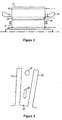
- a squirrel cage induction motor 10 comprises a stator core 11 and a rotor core 12, each having a number of sections 13 and 14, respectively. Both cores are made up of a large number of laminations.
- the stator core 11 is firmly attached to a housing 15 and the rotor core 12 is secured to a shaft 16 which may drive a load (not shown).
- the stator core 11 is provided with a 3-phase winding 17, while the rotor core 12 is equipped with solid aluminium or copper rotor bars 18.
- the rotor bars 18 are shorted together in end rings, one at each end of the rotor.
- the stator core 11 and rotor core 12 are provided with radial ducts 19 through which air is forced in order to cool the stator and rotor.
- Air inside the machine 10 is made to circulate round the machine by a fan 20 secured to the shaft 16.
- the air is drawn in through a number of ducts 21 situated between the rotor core and the shaft 16, and at the same time through an airgap 22 between the stator and rotor, the air then passing through the ducts 19 and over the rear 23 of the stator core, before being returned to the fan 20.
- the air passes through a heat exchanger 24, cooling air being supplied from outside the machine by a further fan 25 also mounted to the shaft 16.
- the laminations of both the stator core and rotor core appear as shown in a simplified representation in Figure 2.
- the stator laminations comprise a body portion 31 and a number of teeth 32. (In practice, the number of teeth in a large rotating machine would be much greater than the number shown in the figure). Between the teeth 32 are slots 33 into which the 3-phase winding 17 (see Figure 1) is inserted.
- each lamination consists of a body portion 35 and a number of teeth 36 and slots 37.
- the slots 37 are suitable shaped to receive the solid bars 18.
- FIG. 3 One known axial ventilation arrangement is shown in Figure 3.
- a ventilation duct 40 is provided in each of the teeth of the stator 11 adjacent to the airgap 22.
- the duct 40 runs the entire axial length of the stator, and air is forced through this duct in order to cool the laminations of the stator core and the windings 17. Additional cooling may be provided by forcing air through small ducts 41, 42 made in the body of the stator core and rotor core, respectively.
- FIG 4 is a partial view of the arrangement of Figure 3 showing a stator tooth 32 and two associated stator slots 33.
- Each slot 33 comprises a winding section 51 and a ventilation duct section 52, which represents the duct 40 in Figure 3.
- the ventilation duct section 52 is sometimes termed a "tunnel slot".
- the winding section 51 accommodates the stator winding 53, which in this example is composed of two sections 54, each made from a number of rectangular conductors held together by a suitable binding means.
- the two sections 54 are kept apart by a separator 55.
- the winding 53 is prevented from moving down the slot 33 by a wedge 56 which runs the length of the stator core 11, or core section 12.
- tunnel slots in such an axial ventilation system makes for inefficient cooling. This is for several reasons: firstly, the cross-sectional area of the tunnel slot 52 is relatively small, which restricts the flow rate of the cooling air and produces an undesirably large pressure drop along the axis of the stator.
- the tunnel slot 52 may be increased in depth to allow a greater throughput of air, but with this must go a reduction in depth of the winding section 51 in order not to prejudice too much the mechanical properties of the stator core.
- the winding 53 must be made shorter and fatter, which necessitates a longer end-winding 17 in order to satisfy minimum clearance requirements at the end-winding itself.
- the surface area of the tunnel slot 52 in contact with the air is restricted, which impairs the cooling efficiency of the arrangement.
- the top part 57 of the winding 53 and its adjacent lamination portions have long heat flow paths 58 to the tunnel slot 52, which produces an undesirably high temperature gradient between these two parts of the slot.
- Figure 4 also shows a pair of rotor bars 18 occupying the slots 37 of the rotor 12.
- FIG. 5 which shows a stator tooth 32 and two adjacent slots 33, the stator tooth 32 is provided with two small ducts 61, 62 running the whole length of the stator core. These ducts serve to provide nominal axial air cooling of the stator laminations only. Cooling of the stator winding (not shown) in the slots 33 is achieved by arranging for the conductors of the winding to be hollow and forcing water through them.
- stator cooling arrangements are illustrated in GB 1,354,247 and in IEEE Transactions on Power Apparatus and Systems, pages 639-643 published 22nd May 1974 and 3rd march 1982, respectively.
- cooling is by triangular ducts formed in the stator teeth through which refrigerant is forced.
- rectangular openings in the stator teeth between the stator windings communicate at intervals with narrow radial openings leading to the airgap; this system is therefore not envisaged as a purely axial system but is an axial/radial cooling system.
- a cage rotor 12 (see Figure 6) is provided with small-diameter air ducts 71 in the rotor teeth 37.
- the arrangement incorporates in addition larger ducts 72 situated in the body of the rotor core below each rotor bar 18.
- the ducts 71 perform essentially cooling of the laminations with some cooling of the rotor bars 18, while ducts 72 take away heat mainly from the rotor bars 18.
- the invention is defined by the features of Claim 1.
- the recess is of such a radial depth as to expose part of an adjacent slot to the duct. This has the effect of directly exposing part of a rotor bar occupying that slot to the cooling air, thereby greatly increasing efficiency of cooling of the bars.
- the rotor teeth are configured so that an unrecessed corner of any one tooth completely bounds the top (short) edge of its associated rotor bar.
- this unrecessed part of the tooth acts as a heat sink when the rotor is stalled. This is significant because when the rotor is locked, rotor slip frequency is at a maximum and most of the current flowing in a rotor bar is crowded toward the top end of the bar. Having laminations all the way along that short top edge helps to dissipate a substantial part of the heat which is thereby produced.
- a preferred embodiment of the invention is defined in Claim 4.
- the inventors have recognised that, on 2-pole machines especially, the flux densities in the stator teeth are relatively low, which means that the teeth are under-utilised. It has been found that, by providing the teeth with fairly large openings, ducts may be thereby formed for the influx of air for cooling the windings, while at the same time leaving the magnetic performance of the core relatively unaffected.
- the rise in flux density in the teeth occasioned by this measure can be somewhat offset for a given opening area by narrowing the slots and thereby increasing the flux-carrying width of the teeth. Narrowing the slots also makes for narrower windings in the slots. This means that the stator end windings can be made shorter, and therefore the machine can be made smaller. This in turn has the advantage of reducing the length of the shaft carrying the rotor, and thus the bearing centres can be brought closer and the stiffness of the shaft increased.
- a number of configurations are possible for the one or more openings.
- a preferred configuration is to have two rectangular or trapezoidal holes disposed end-to-end along the radial axis of the tooth and separated by a bridge section, the holes being situated approximately midway along the width of the tooth.
- two such pairs of holes may be employed side by side along the width of the tooth and suitably spaced from each other and from the adjacent slots.
- each lamination making up the stator core may be provided with one or more recesses along one edge of the tooth, i.e. where the tooth borders onto an adjacent slot.
- Such recesses may be configured in a manner similar to the above holes.
- a preferred arrangement is to have two rectangular or trapezoidal recesses disposed end-to-end along one radial edge of the tooth and separated by a bridge section.
- two such pairs of recesses may be employed along opposite edges of the tooth.
- a further possible opening configuration is to have one opening or recess only running along most of the radial depth of the tooth.
- the single opening may be a hole situated approximately midway along the width of the tooth, or a recess disposed along one radial edge of the tooth. This latter arrangement is not a preferred configuration, however, since it makes for difficulties in preventing migration of the adjacent winding into the recess.
- the use of a bridge section in the double (end-to-end) recess configuration has the advantage of controlling such migration.
- a further possible configuration is to use two such single openings side by side. Again, the preferred arrangement in this case is to have two long holes suitably spaced along the width of the tooth. The use of two long recesses along opposite edges of the tooth would suffer from the same winding migration problem as the use of a single recess along only one edge.
- An opening area created by the one or more openings may extend beyond the radial depth of the tooth. This has the effect of increasing the available duct volume per tooth and is a possible measure, especially in the stator, where the flux density in the core will not thereby be made excessive or where mechanical stiffness considerations of the stator core will not be a prohibiting factor. This latter proviso is mitigated somewhat by the presence of part of the tooth around the opening, which tends to increase the stiffness of the stator core.
- the stator or rotor core may comprise one or more radial ventilation ducts for use in a double-ended axial ventilation arrangement. This is useful where the invention is required to be used in a very large machine with a correspondingly large cooling requirement.
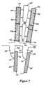
- Figure 7 shows a partial view of a stator and rotor core assembly in a preferred embodiment of the invention.
- the two cores are part of a 2-pole cage induction motor and, since cooling is by axial, not radial, ventilation, the cores consist of only one core section.
- Each core comprises a large number of laminations placed together in a stack.
- the diagram shows a stator tooth 101 bounded by two stator slots 102, and a winding 103, which is divided into two layers 117, is shown inserted into the slots 102 in the stator core. The windings are held in place by wedges 104.
- each lamination of the stator core are stamped two openings in the form of holes 105 with a bridge piece 116 left between them, such that there is formed along the axial length of the stator core two ventilation ducts per tooth allowing the flow of air through the tooth portion of the core.
- the bridge piece 116 helps to maintain adequate rigidity of the tooth 101.
- the upper opening 105 is arranged to extend beyond the radial depth of the slots 102 into the body of the stator, and the total end-to-end radial depth of the two openings is greater than one-half of the depth of the slots 102.
- a fan blows air through the ducts made by the holes 105 and carries heat away from the winding 103 via very short thermal paths 106 in each lamination. These paths run in parallel all the way along the axis of the stator, there being a total cooling surface area per tooth equal to the sum of the measurements of the perimeters of the two openings 105 in the tooth multiplied by the axial length of the stator. This has the effect of cooling very efficiently not only the tooth laminations, but also the windings 103.
- the cooling air is circulated around the machine and dissipates its heat to a heat exchanger (see Figure 1).
- the laminations which make up the rotor core are arranged to have their own openings 110 in the rotor teeth 109.
- the openings 110 are recesses which create, in a manner similar to the holes 105 in the stator laminations, ventilation ducts along the axial length of the rotor core.
- bars 111 are mounted in the rotor slots 118 and shorted to each other at either end of the rotor core.
- the recesses 110 By arranging for the recesses 110 to start at some point 112 along the radial length of the respective rotor bars 111, a significant proportion of one face 113 of each bar is exposed to air and is thereby directly cooled by the contacting air.
- the other face 114 of each rotor bar 111 is separated from the next recess in the series by only a comparatively short thermal path 115, which also assists in cooling the bar. This provides efficient removal of heat from the bars and rotor laminations.
- the recess 110 in each of the rotor laminations increases the local turbulence in the airgap 112, which improves the transfer of heat away from the rotor laminations and bars 111.
- a further effect of the recesses 110 is that they reduce the mass and therefore inertia of the rotor.
- the thermal conductivity of the metal used for the laminations must be used in calculations, not that of the metal and insulation in series.
- Thermal conductivity for the pure metal is approximately 30 W/mK. This means that there is, in the invention, a total gain in cooling efficiency of 25/7 x 30/2.2 ⁇ 55 when comparing the hottest parts of the two arrangements.
- FIG 8. A second embodiment of a stator assembly according to the invention is shown in Figure 8.
- the stator laminations have stamped in them two openings 120 in the tooth 101. These openings, which are recesses, differ from the holes 105 in the first embodiment of the stator assembly in that they are arranged to be a continuation of the slot 102, thereby leaving a substantially narrowed radially extending tooth portion 121.
- This configuration functions in a manner similar to the rotor recesses in Figure 7: one face 122 of the windings 103 is directly cooled by air flowing through the ducts formed by the recesses 120, while the other face 123 has a short thermal path 124 to the recesses of the next tooth.
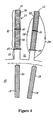
- the openings in the stator may be configured in other ways. Examples of other configurations are shown in Figure 9.
- Figure 9a shows alternative forms of openings in the form of holes
- Figure 9b shows the equivalent in the form of recesses.
- the holes/recesses are, in each case, shown hatched.
- a single long opening only may be used, though in the case of the single recess shown in Figure 9b this may entail difficulties with regard to the anchoring of the winding in the adjacent slot.
- two long but narrower openings may be used side by side; this has the same disadvantage as the single-opening arrangement.
- four openings may be employed in the form of two pairs of the openings shown in the first embodiment of the stator assembly, Figure 7.
- Figure 10 shows a simplified sectional view of a rotating machine according to the invention highlighting the airflow which takes place inside the machine.
- Air enters the machine compartment from the right, having been forced through a heat exchanger 24 by a fan 20.
- the air then follows three parallel paths, A, B and C: A is a path behind the body of the stator core; B is a path through the openings in the stator teeth, and C is a path through the recesses in the rotor teeth and through the airgap.
- the openings in order to increase the cooling surface area of the ducts created by the openings, it is possible to provide the openings with corrugated edges, as shown in Figure 11.
- the corrugations may be on the longer edges or on all the edges of an opening, depending on ease of manufacture.
- FIG. 12 An example of double-ended axial ventilation is shown in Figure 12.
- the stator 11 is equipped with three radial ducts 19, the rotor 12 with none.
- a fan 20 is placed at either end of the machine on the shaft 16, and these fans draw air into both ends of the machine simultaneously along the same three paths illustrated in Figure 10. Air flowing along the stator tooth ducts and the rotor tooth ducts (where this is a recess) and airgap is then forced through the radial ducts 19 when it reaches the central part of the machine and is taken up through the heat exchanger 24 before recirculating through the machine.
Landscapes
- Engineering & Computer Science (AREA)
- Power Engineering (AREA)
- Iron Core Of Rotating Electric Machines (AREA)
- Motor Or Generator Cooling System (AREA)
- Motor Or Generator Frames (AREA)
- Control Of Electric Motors In General (AREA)
Claims (15)
- Noyau de rotor destiné à une machine d'induction à cage comprenant plusieurs dents (109), plusieurs fentes (118) pour barres de rotor et une barre de rotor (111) contenue dans chaque fente, chacune desdites dents ayant une cavité (110) dans un coin externe d'un côté de la dent de façon telle que, en conjonction avec une barre de rotor correspondante (111), chaque cavité (110) forme un conduit de ventilation d'air s'étendant sur la longueur axiale du noyau de rotor, la cavité ayant une profondeur radiale telle qu'elle expose une proportion significative d'une face (113) de la barre de rotor au conduit de telle sorte que la barre de rotor est directement refroidie au contact de l'air.
- Noyau de rotor selon la revendication 1, dans lequel la cavité (110) est telle que le trajet thermique (115) entre chaque barre de rotor (111) et la prochaine cavité (110) de la série est comparativement plus court.
- Noyau de rotor selon la revendication 1 du la revendication 2, dans lequel chaque barre de rotor (111) est retenue dans sa fente (118) par une partie d'une dent adjacente (109) qui s'étend au-dessus de la fente en contact avec le côté supérieur (119) de la barre de rotor.
- Machine d'induction à cage comprenant un noyau de rotor selon la revendication 1 et un noyau de stator, le noyau de stator ayant une pluralité de dents (101), chacune desdites dents de stator ayant une ou plusieurs ouvertures (105, 120) s'étendant suivant une longueur axiale du noyau, l'ouverture ou les ouvertures dans chaque dent de stator ayant des dimensions telles qu'elles donnent une profondeur radiale totale d'ouverture qui s'étend sur la plus grande partie de la profondeur radiale de la dent de stator, les ouvertures de la dent de stator formant des conduits pour la circulation de l'air de refroidissement.
- Machine d'induction à cage selon la revendication 4, dans laquelle les ouvertures (105) de chaque dent de stator (101) comportent deux ouvertures (105) placées bout à bout suivant la profondeur radiale de la dent de stator.
- Machine d'induction à cage selon la revendication 5, dans laquelle les ouvertures sont des trous (105) disposés pratiquement au centre suivant la largeur de la dent de stator.
- Machine d'induction à cage selon la revendication 5, dans laquelle les ouvertures sont des cavités (120) disposées le long d'un bord radial de la dent de stator.
- Machine d'induction à cage selon la revendication 5, comprenant une paire supplémentaire d'ouvertures disposées bout à bout suivant la profondeur radiale de la dent de stator le long de la première paire.
- Machine d'induction à cage selon la revendication 8, dans laquelle les ouvertures sont des trous.
- Machine d'induction à cage selon la revendication 8, dans laquelle les ouvertures sont des cavités, les paires de cavités étant placées le long de bords radiaux opposés de la dent de stator.
- Machine d'induction à cage selon la revendication 4, dans laquelle les ouvertures de chaque dent de stator comportent deux ouvertures disposées côte à côte suivant la largeur de la dent de stator, chaque ouverture ayant une profondeur radiale qui s'étend sur la plus grande partie de la profondeur de la dent de stator.
- Machine d'induction à cage selon la revendication 11, dans laquelle les ouvertures sont des trous.
- Machine d'induction à cage selon la revendication 11, dans laquelle les ouvertures sont des cavités placées le long des bords radiaux opposés de la dent de stator.
- Machine d'induction à cage selon les revendications 4, 5, 6, 8, 9, 11 et 12, dans laquelle une zone d'ouverture créée par l'ouverture ou plusieurs ouvertures s'étend au-delà de la profondeur radiale de la dent de stator.
- Machine d'induction à cage selon l'une quelconque des revendications 4 à 14, comprenant un ou plusieurs conduits radiaux formés dans le noyau de rotor et/ou le noyau de stator et destinés à être utilisés dans un ensemble de ventilation axiale à deux extrémités.
Applications Claiming Priority (2)
| Application Number | Priority Date | Filing Date | Title |
|---|---|---|---|
| GB9410351A GB2289992B (en) | 1994-05-24 | 1994-05-24 | Improvements in or relating to cooling arrangements in rotating electrical machines |
| GB9410351 | 1994-05-24 |
Publications (3)
| Publication Number | Publication Date |
|---|---|
| EP0684682A1 EP0684682A1 (fr) | 1995-11-29 |
| EP0684682B1 EP0684682B1 (fr) | 1998-07-01 |
| EP0684682B2 true EP0684682B2 (fr) | 2004-08-25 |
Family
ID=10755606
Family Applications (1)
| Application Number | Title | Priority Date | Filing Date |
|---|---|---|---|
| EP95302626A Expired - Lifetime EP0684682B2 (fr) | 1994-05-24 | 1995-04-20 | Améliorations relatives aux dispositifs de refroidissement pour machines électriques tournantes |
Country Status (8)
| Country | Link |
|---|---|
| US (1) | US5866959A (fr) |
| EP (1) | EP0684682B2 (fr) |
| JP (1) | JP3663588B2 (fr) |
| AT (1) | ATE167965T1 (fr) |
| CA (1) | CA2148213C (fr) |
| DE (1) | DE69503190T3 (fr) |
| FI (1) | FI116252B (fr) |
| GB (1) | GB2289992B (fr) |
Cited By (5)
| Publication number | Priority date | Publication date | Assignee | Title |
|---|---|---|---|---|
| US6801421B1 (en) | 1998-09-29 | 2004-10-05 | Abb Ab | Switchable flux control for high power static electromagnetic devices |
| US6822363B2 (en) | 1996-05-29 | 2004-11-23 | Abb Ab | Electromagnetic device |
| US6825585B1 (en) | 1997-02-03 | 2004-11-30 | Abb Ab | End plate |
| US6828701B1 (en) | 1997-02-03 | 2004-12-07 | Asea Brown Boveri Ab | Synchronous machine with power and voltage control |
| US6831388B1 (en) | 1996-05-29 | 2004-12-14 | Abb Ab | Synchronous compensator plant |
Families Citing this family (72)
| Publication number | Priority date | Publication date | Assignee | Title |
|---|---|---|---|---|
| WO1997045914A1 (fr) * | 1996-05-29 | 1997-12-04 | Asea Brown Boveri Ab | Generateur electrique rotatif avec refroidissement axial |
| AU2989197A (en) | 1996-05-29 | 1998-01-05 | Asea Brown Boveri Ab | Conductor for high-voltage windings and a rotating electric machine comprising a winding including the conductor |
| SE510192C2 (sv) | 1996-05-29 | 1999-04-26 | Asea Brown Boveri | Förfarande och kopplingsarrangemang för att minska problem med tredjetonsströmmar som kan uppstå vid generator - och motordrift av växelströmsmaskiner kopplade till trefas distributions- eller transmissionsnät |
| CN1220039A (zh) | 1996-05-29 | 1999-06-16 | Abb阿西亚布朗·勃法瑞公司 | 用于高压绕组的绝缘导体及其制作方法 |
| WO1997045916A1 (fr) * | 1996-05-29 | 1997-12-04 | Asea Brown Boveri Ab | Tubes de refroidissement axiaux avec moyens de serrage |
| US5751079A (en) * | 1996-10-17 | 1998-05-12 | Ford Motor Company | Alternator with internal and external fans |
| SE510422C2 (sv) | 1996-11-04 | 1999-05-25 | Asea Brown Boveri | Magnetplåtkärna för elektriska maskiner |
| SE512917C2 (sv) | 1996-11-04 | 2000-06-05 | Abb Ab | Förfarande, anordning och kabelförare för lindning av en elektrisk maskin |
| SE509072C2 (sv) | 1996-11-04 | 1998-11-30 | Asea Brown Boveri | Anod, anodiseringsprocess, anodiserad tråd och användning av sådan tråd i en elektrisk anordning |
| SE515843C2 (sv) | 1996-11-04 | 2001-10-15 | Abb Ab | Axiell kylning av rotor |
| SE508543C2 (sv) | 1997-02-03 | 1998-10-12 | Asea Brown Boveri | Hasplingsanordning |
| SE9704421D0 (sv) | 1997-02-03 | 1997-11-28 | Asea Brown Boveri | Seriekompensering av elektrisk växelströmsmaskin |
| SE9704423D0 (sv) | 1997-02-03 | 1997-11-28 | Asea Brown Boveri | Roterande elektrisk maskin med spolstöd |
| SE508544C2 (sv) | 1997-02-03 | 1998-10-12 | Asea Brown Boveri | Förfarande och anordning för montering av en stator -lindning bestående av en kabel. |
| SE9704427D0 (sv) | 1997-02-03 | 1997-11-28 | Asea Brown Boveri | Infästningsanordning för elektriska roterande maskiner |
| DE19751055A1 (de) * | 1997-11-18 | 1999-05-20 | Abb Patent Gmbh | Gasgekühlter Turbogenerator |
| GB2331867A (en) | 1997-11-28 | 1999-06-02 | Asea Brown Boveri | Power cable termination |
| AU9362998A (en) | 1997-11-28 | 1999-06-16 | Asea Brown Boveri Ab | Method and device for controlling the magnetic flux with an auxiliary winding ina rotating high voltage electric alternating current machine |
| KR19990013313A (ko) * | 1998-02-11 | 1999-02-25 | 이이수 | 무변출력 무정류자 직류전동기 |
| US6069423A (en) * | 1999-04-21 | 2000-05-30 | Vita-Mix Corporation | Motor cooling and sound absorbing system |
| US7211919B2 (en) * | 1999-08-16 | 2007-05-01 | American Superconductor Corporation | Thermally-conductive stator support structure |
| DE10008807A1 (de) * | 2000-02-25 | 2001-09-06 | Siemens Ag | Elektrische Rotationsmaschine und Verfahren zum Kühlen einer elektrischen Rotationsmaschine |
| DE10059387A1 (de) * | 2000-11-30 | 2002-06-06 | Alstom Switzerland Ltd | Rotor für eine elektrische rotierende Maschine |
| JP3624825B2 (ja) * | 2000-12-14 | 2005-03-02 | 日産自動車株式会社 | 回転電機および回転電機の製造方法 |
| US6794773B2 (en) | 2001-01-23 | 2004-09-21 | General Electric Company | Winding restraint on wound rotor generators or motors and method for forming the same |
| US6680551B2 (en) | 2001-08-20 | 2004-01-20 | Hamilton Beach/Proctor-Silex | Electric motor muffler |
| US6933633B2 (en) | 2001-10-03 | 2005-08-23 | Nissan Motor Co., Ltd. | Rotating electric machine and cooling structure for rotating electric machine |
| US6819016B2 (en) * | 2002-07-18 | 2004-11-16 | Tm4 Inc. | Liquid cooling arrangement for electric machines |
| DE10244202A1 (de) | 2002-09-23 | 2004-03-25 | Alstom (Switzerland) Ltd. | Elektrische Maschine mit einem Stator mit gekühlten Wicklungsstäben |
| DE10329678A1 (de) * | 2003-07-01 | 2005-02-03 | Siemens Ag | Elektromotor für einen Antrieb eines Fahrzeugs, insbesondere Bahnantriebe, sowie einen Antrieb mit einem solchen Elektromotor |
| DE102004013133A1 (de) * | 2004-03-17 | 2005-10-13 | Siemens Ag | Elektrische Maschine mit verbesserter Kühlung und entsprechendes Kühlverfahren |
| US7775576B2 (en) * | 2004-06-25 | 2010-08-17 | Robert Bosch Gmbh | Air pump assembly |
| EP1787380B1 (fr) * | 2004-09-09 | 2012-07-04 | Siemens Aktiengesellschaft | Ensemble de plusieurs modules de refroidisseurs et d'un bôitier de machine |
| US7348697B2 (en) * | 2004-09-09 | 2008-03-25 | Siemens Energy & Automation, Inc. | System for ventilating a motor |
| DE102006025487A1 (de) * | 2005-06-07 | 2006-12-14 | Alstom Technology Ltd. | Dynamoelektrische Maschine mit einem bürstenlosen Erreger |
| US7791238B2 (en) * | 2005-07-25 | 2010-09-07 | Hamilton Sundstrand Corporation | Internal thermal management for motor driven machinery |
| US7619345B2 (en) * | 2006-01-30 | 2009-11-17 | American Superconductor Corporation | Stator coil assembly |
| US7579724B2 (en) * | 2006-06-02 | 2009-08-25 | General Electric Company | Methods and apparatus for using an electrical machine to transport fluids through a pipeline |
| US8129880B2 (en) * | 2007-11-15 | 2012-03-06 | GM Global Technology Operations LLC | Concentrated winding machine with magnetic slot wedges |
| US7928616B2 (en) | 2008-05-19 | 2011-04-19 | General Electric Company | Systems and apparatus involving toothed armatures in superconducting machines |
| DE102009031548A1 (de) * | 2009-07-02 | 2011-01-05 | Siemens Aktiengesellschaft | Ständer für eine elektrische Maschine |
| IT1403055B1 (it) * | 2010-11-30 | 2013-09-27 | Itaco S R L Ora Reel S R L | Generatore elettrico. |
| US9729020B2 (en) | 2011-03-22 | 2017-08-08 | Hamilton Sundstrand Corporation | Motor stator having channels used for cooling and method of providing the channels |
| JP5869798B2 (ja) * | 2011-08-04 | 2016-02-24 | ダイヤモンド電機株式会社 | ブラシレスモータ,及び,これを備える電動パワーステアリング装置 |
| DE102011053299A1 (de) * | 2011-09-06 | 2013-03-07 | Antriebstechnik Katt Hessen Gmbh | Kühlsystem für eine hochausgenutzte hochtourige rotierende elektrische Synchronmaschine |
| US9225208B2 (en) * | 2011-09-30 | 2015-12-29 | Hamilton Sundstrand Corporation | Internal cooling of magnetic core for electric machine |
| US9118232B2 (en) * | 2011-12-29 | 2015-08-25 | Qubo Li | Electric machine cooling system |
| WO2013165629A2 (fr) * | 2012-04-30 | 2013-11-07 | Parker-Hannifin Corporation | Servomoteur à refroidissement interne à stator segmenté |
| JP5918656B2 (ja) * | 2012-08-28 | 2016-05-18 | 東芝三菱電機産業システム株式会社 | 回転電機 |
| EP2811620A1 (fr) * | 2013-06-06 | 2014-12-10 | Siemens Aktiengesellschaft | Dispositif de refroidissement pour un enroulement d'une machine électrique |
| DE102014211672A1 (de) * | 2013-07-12 | 2015-01-15 | Schaeffler Technologies Gmbh & Co. Kg | Elektrische Maschine |
| CN104377852B (zh) * | 2013-08-13 | 2016-12-28 | 珠海格力电器股份有限公司 | 永磁电机、制冷压缩机及空调机组 |
| US9653954B2 (en) * | 2013-09-18 | 2017-05-16 | Siemens Industry, Inc. | Electric machine rotor with rotor vent and axial slot fluid communication |
| JP5977298B2 (ja) * | 2014-09-03 | 2016-08-24 | 東芝三菱電機産業システム株式会社 | 全閉式回転電機 |
| EP3198706A1 (fr) * | 2014-09-25 | 2017-08-02 | Heatex AB | Unité d'échange de chaleur |
| EP3032707A1 (fr) * | 2014-12-08 | 2016-06-15 | Siemens Aktiengesellschaft | Agencement de refroidissement |
| JP6490046B2 (ja) * | 2016-12-28 | 2019-03-27 | 東芝三菱電機産業システム株式会社 | 全閉外扇形回転電機 |
| FI20175174L (fi) | 2017-02-24 | 2018-08-25 | Lappeenrannan Teknillinen Yliopisto | Oikosulkukoneen roottori |
| CN107769465A (zh) * | 2017-12-04 | 2018-03-06 | 江苏航天动力机电有限公司 | 新型的电机强迫通风冷却器结构 |
| DE102018208706A1 (de) * | 2018-06-04 | 2019-12-05 | Audi Ag | System zum Kühlen einer Elektromaschine |
| US10923969B2 (en) * | 2019-01-14 | 2021-02-16 | GM Global Technology Operations LLC | Molded core assemblies for a motor-generator |
| US11411448B2 (en) * | 2019-09-03 | 2022-08-09 | Hamilton Sundstrand Corporation | Motor stator core design with integral cooling duct within teeth |
| DE102019131069A1 (de) * | 2019-11-18 | 2021-05-20 | Dr. Ing. H.C. F. Porsche Aktiengesellschaft | Stator für eine elektrische Maschine mit verbesserter Kühlung, elektrische Maschine, Kraftfahrzeug |
| EP3840189A1 (fr) | 2019-12-20 | 2021-06-23 | Volvo Car Corporation | Rotor pour système de refroidissement d'air |
| WO2021229888A1 (fr) * | 2020-05-15 | 2021-11-18 | 株式会社Ihi | Stator de moteur électrique et moteur électrique |
| EP3955424A1 (fr) | 2020-08-10 | 2022-02-16 | Siemens Aktiengesellschaft | Machine dynamoélectrique à refroidissement par liquide |
| CN112564358B (zh) * | 2020-11-10 | 2022-06-28 | 湖南科技大学 | 交流牵引电机转子齿部轴向通风槽的设计方法 |
| EP4016814A1 (fr) | 2020-12-17 | 2022-06-22 | Flender GmbH | Stator, procédé de fabrication, simulation, produit de programme informatique |
| EP4024680A1 (fr) | 2021-01-05 | 2022-07-06 | Flender GmbH | Stator, procédé de simulation, produit programme informatique |
| US12009696B2 (en) * | 2021-05-24 | 2024-06-11 | Hamilton Sundstrand Corporation | Two phase cooling for electric machine |
| EP4145677A1 (fr) * | 2021-09-06 | 2023-03-08 | MAHLE International GmbH | Machine électrique |
| US12126224B2 (en) * | 2022-01-28 | 2024-10-22 | Ge Aviation Systems Llc | Method and apparatus for cooling a rotor assembly |
Family Cites Families (22)
| Publication number | Priority date | Publication date | Assignee | Title |
|---|---|---|---|---|
| DE295610C (fr) * | ||||
| DE252335C (fr) * | ||||
| GB191203106A (en) * | 1912-02-07 | 1912-07-18 | Siemens Brothers Dynamo Works | Improvements in or relating to Cooling Arrangements for Dynamo-electric Machinery. |
| GB252335A (en) * | 1925-05-25 | 1926-09-23 | Thyssen & Co Ag | Improvements in and relating to rotors for dynamo-electric machines |
| GB358240A (en) * | 1930-09-17 | 1931-10-08 | William Norman Kilner | Improvements in dynamo electric machines |
| US1996460A (en) * | 1933-03-31 | 1935-04-02 | Chicago Pneumatic Tool Co | Ventilated induction motor |
| FR929566A (fr) * | 1946-06-21 | 1947-12-31 | Thomson Houston Comp Francaise | Procédé de stabilisation des hydrocarbures halogènes employés comme isolants |
| DE929566C (de) * | 1952-02-02 | 1955-06-30 | Licentia Gmbh | Induktorkuehlung bei Turbogeneratoren mit einseitig neben den in Nuten eingebetteten Wicklungen liegenden Kuehlungsnuten und Haltestuecken |
| GB938180A (en) * | 1960-05-10 | 1963-10-02 | Parsons C A & Co Ltd | Improvements in and relating to the cooling of dynamo-electric machines |
| GB1076839A (en) * | 1963-12-07 | 1967-07-26 | Siemens Ag | A rotor for an asynchronous motor |
| GB1354247A (en) * | 1972-05-30 | 1974-06-05 | Gen Electric | Dynamoelectric machine |
| DE2340691A1 (de) * | 1973-08-10 | 1975-02-27 | Siemens Ag | Staenderblechpaket fuer eine kompensierte gleichstrommaschine |
| US4217511A (en) * | 1978-06-13 | 1980-08-12 | Westinghouse Electric Corp. | Stator core cooling for dynamoelectric machines |
| US4208597A (en) * | 1978-06-22 | 1980-06-17 | Westinghouse Electric Corp. | Stator core cooling for dynamoelectric machines |
| DE2912592A1 (de) * | 1979-03-28 | 1980-10-09 | Siemens Ag | Elektrische maschine mit lamelliertem blechpaket |
| US4311932A (en) * | 1980-01-28 | 1982-01-19 | Sundstrand Corporation | Liquid cooling for induction motors |
| JPS58215954A (ja) * | 1982-06-07 | 1983-12-15 | Mitsubishi Electric Corp | 回転電機の回転子 |
| DE3444189A1 (de) * | 1984-03-21 | 1985-09-26 | Kraftwerk Union AG, 4330 Mülheim | Einrichtung zur indirekten gaskuehlung der staenderwicklung und/oder zur direkten gaskuehlung des staenderblechpaketes dynamoelektrischer maschinen, vorzugsweise fuer gasgekuehlte turbogeneratoren |
| SE462310B (sv) * | 1988-10-14 | 1990-05-28 | Asea Brown Boveri | Kortsluten asynkronmotor foer frekvensomriktardrift |
| JPH03222651A (ja) * | 1989-11-06 | 1991-10-01 | Toshiba Corp | 空冷式誘導電動機 |
| US5182483A (en) * | 1989-12-28 | 1993-01-26 | Kabushiki Kaisha Toshiba | Squirrel-cage rotor with shaped-conductor harmonic reduction |
| US4994700A (en) * | 1990-02-15 | 1991-02-19 | Sundstrand Corporation | Dynamoelectric machine oil-cooled stator winding |
-
1994
- 1994-05-24 GB GB9410351A patent/GB2289992B/en not_active Expired - Fee Related
-
1995
- 1995-04-20 AT AT95302626T patent/ATE167965T1/de active
- 1995-04-20 EP EP95302626A patent/EP0684682B2/fr not_active Expired - Lifetime
- 1995-04-20 DE DE69503190T patent/DE69503190T3/de not_active Expired - Lifetime
- 1995-04-28 CA CA002148213A patent/CA2148213C/fr not_active Expired - Lifetime
- 1995-05-15 JP JP14001195A patent/JP3663588B2/ja not_active Expired - Lifetime
- 1995-05-23 FI FI952501A patent/FI116252B/fi not_active IP Right Cessation
-
1997
- 1997-08-04 US US08/905,492 patent/US5866959A/en not_active Expired - Lifetime
Cited By (5)
| Publication number | Priority date | Publication date | Assignee | Title |
|---|---|---|---|---|
| US6822363B2 (en) | 1996-05-29 | 2004-11-23 | Abb Ab | Electromagnetic device |
| US6831388B1 (en) | 1996-05-29 | 2004-12-14 | Abb Ab | Synchronous compensator plant |
| US6825585B1 (en) | 1997-02-03 | 2004-11-30 | Abb Ab | End plate |
| US6828701B1 (en) | 1997-02-03 | 2004-12-07 | Asea Brown Boveri Ab | Synchronous machine with power and voltage control |
| US6801421B1 (en) | 1998-09-29 | 2004-10-05 | Abb Ab | Switchable flux control for high power static electromagnetic devices |
Also Published As
| Publication number | Publication date |
|---|---|
| DE69503190T3 (de) | 2005-12-15 |
| CA2148213C (fr) | 2005-02-08 |
| CA2148213A1 (fr) | 1995-11-25 |
| DE69503190T2 (de) | 1998-12-03 |
| JPH07322565A (ja) | 1995-12-08 |
| ATE167965T1 (de) | 1998-07-15 |
| JP3663588B2 (ja) | 2005-06-22 |
| FI952501A0 (fi) | 1995-05-23 |
| EP0684682B1 (fr) | 1998-07-01 |
| GB9410351D0 (en) | 1994-07-13 |
| FI952501A (fi) | 1995-11-25 |
| GB2289992A (en) | 1995-12-06 |
| GB2289992B (en) | 1998-05-20 |
| FI116252B (fi) | 2005-10-14 |
| US5866959A (en) | 1999-02-02 |
| EP0684682A1 (fr) | 1995-11-29 |
| DE69503190D1 (de) | 1998-08-06 |
Similar Documents
| Publication | Publication Date | Title |
|---|---|---|
| EP0684682B2 (fr) | Améliorations relatives aux dispositifs de refroidissement pour machines électriques tournantes | |
| US20200136451A1 (en) | Synchronous reluctance machine | |
| EP1220424A1 (fr) | Machine dynamo-electrique | |
| KR101755669B1 (ko) | 다이나모일렉트릭 머신용 로터, 냉각 가스 통기 침니 및 다이나모일렉트릭 머신 | |
| US5084641A (en) | Air-cooled type induction motor for use in vehicles having means to reduce exhaust air noise | |
| KR100854197B1 (ko) | 가스 냉각식 발전기 기계 및 엔드와인딩 냉각 방법 | |
| US2221567A (en) | Turbogenerator rotor | |
| US4508985A (en) | Dynamoelectric machine with rotor ventilation system including axial duct inlet fairing | |
| JP2004516789A (ja) | 発電機コイル端の増大された冷却のためのスペースブロックデフレクタ | |
| JP3737480B2 (ja) | ロータ空洞の熱伝導を増強するためのスペースブロックスクープ | |
| JP3453058B2 (ja) | 回転電機の固定子 | |
| JP2004516796A (ja) | 発電機ロータのコイル端における空洞流れを増強するための後流減少構造 | |
| JPH09285052A (ja) | 回転電機 | |
| US6870299B1 (en) | Thermal management of rotor endwinding coils | |
| EP0579625B1 (fr) | Rotor pour moteur a courant alternatif en court-circuit | |
| JP3832187B2 (ja) | 圧縮機用電動モータ | |
| JPH10295052A (ja) | 回転電機の回転子の冷却構造 | |
| JPH08205435A (ja) | 回転電機の固定子鉄心 | |
| JP2002369472A (ja) | 誘導電動機のロータ構造 | |
| US20040084975A1 (en) | Gas-cooled generator stator | |
| JP2000308293A (ja) | 回転電機 | |
| CA1164032A (fr) | Moteur a carcasse fermee refroidi par ventilateur | |
| JPH09247877A (ja) | 回転電機の固定子 | |
| JPS60170441A (ja) | 電動機 | |
| KR19990058914A (ko) | 선형유도전동기의 냉각장치 |
Legal Events
| Date | Code | Title | Description |
|---|---|---|---|
| PUAI | Public reference made under article 153(3) epc to a published international application that has entered the european phase |
Free format text: ORIGINAL CODE: 0009012 |
|
| AK | Designated contracting states |
Kind code of ref document: A1 Designated state(s): AT BE CH DE FR GB IT LI NL SE |
|
| 17P | Request for examination filed |
Effective date: 19960529 |
|
| 17Q | First examination report despatched |
Effective date: 19961217 |
|
| GRAG | Despatch of communication of intention to grant |
Free format text: ORIGINAL CODE: EPIDOS AGRA |
|
| GRAG | Despatch of communication of intention to grant |
Free format text: ORIGINAL CODE: EPIDOS AGRA |
|
| GRAG | Despatch of communication of intention to grant |
Free format text: ORIGINAL CODE: EPIDOS AGRA |
|
| GRAH | Despatch of communication of intention to grant a patent |
Free format text: ORIGINAL CODE: EPIDOS IGRA |
|
| GRAH | Despatch of communication of intention to grant a patent |
Free format text: ORIGINAL CODE: EPIDOS IGRA |
|
| GRAA | (expected) grant |
Free format text: ORIGINAL CODE: 0009210 |
|
| AK | Designated contracting states |
Kind code of ref document: B1 Designated state(s): AT BE CH DE FR IT LI NL SE |
|
| REF | Corresponds to: |
Ref document number: 167965 Country of ref document: AT Date of ref document: 19980715 Kind code of ref document: T |
|
| ITF | It: translation for a ep patent filed | ||
| REG | Reference to a national code |
Ref country code: CH Ref legal event code: NV Representative=s name: JOHN P. MUNZINGER INGENIEUR-CONSEIL Ref country code: CH Ref legal event code: EP |
|
| ET | Fr: translation filed | ||
| RBV | Designated contracting states (corrected) |
Designated state(s): AT BE CH DE FR IT LI NL SE |
|
| REF | Corresponds to: |
Ref document number: 69503190 Country of ref document: DE Date of ref document: 19980806 |
|
| RAP2 | Party data changed (patent owner data changed or rights of a patent transferred) |
Owner name: ALSTOM UK LTD |
|
| PLBI | Opposition filed |
Free format text: ORIGINAL CODE: 0009260 |
|
| PLBF | Reply of patent proprietor to notice(s) of opposition |
Free format text: ORIGINAL CODE: EPIDOS OBSO |
|
| 26 | Opposition filed |
Opponent name: SIEMENS AKTIENGESELLSCHAFT, BERLIN UND MUENCHEN Effective date: 19990331 |
|
| NLT2 | Nl: modifications (of names), taken from the european patent patent bulletin |
Owner name: ALSTOM UK LTD |
|
| NLR1 | Nl: opposition has been filed with the epo |
Opponent name: SIEMENS AKTIENGESELLSCHAFT, BERLIN UND MUENCHEN |
|
| PLBF | Reply of patent proprietor to notice(s) of opposition |
Free format text: ORIGINAL CODE: EPIDOS OBSO |
|
| PLBF | Reply of patent proprietor to notice(s) of opposition |
Free format text: ORIGINAL CODE: EPIDOS OBSO |
|
| PLAW | Interlocutory decision in opposition |
Free format text: ORIGINAL CODE: EPIDOS IDOP |
|
| APAC | Appeal dossier modified |
Free format text: ORIGINAL CODE: EPIDOS NOAPO |
|
| APAE | Appeal reference modified |
Free format text: ORIGINAL CODE: EPIDOS REFNO |
|
| APAC | Appeal dossier modified |
Free format text: ORIGINAL CODE: EPIDOS NOAPO |
|
| APBU | Appeal procedure closed |
Free format text: ORIGINAL CODE: EPIDOSNNOA9O |
|
| NLT1 | Nl: modifications of names registered in virtue of documents presented to the patent office pursuant to art. 16 a, paragraph 1 |
Owner name: ALSTOM UK LTD Owner name: ALSTOM UK |
|
| PUAH | Patent maintained in amended form |
Free format text: ORIGINAL CODE: 0009272 |
|
| STAA | Information on the status of an ep patent application or granted ep patent |
Free format text: STATUS: PATENT MAINTAINED AS AMENDED |
|
| 27A | Patent maintained in amended form |
Effective date: 20040825 |
|
| AK | Designated contracting states |
Kind code of ref document: B2 Designated state(s): AT BE CH DE FR IT LI NL SE |
|
| REG | Reference to a national code |
Ref country code: SE Ref legal event code: RPEO |
|
| REG | Reference to a national code |
Ref country code: CH Ref legal event code: AEN Free format text: MAINTIEN DU BREVET DONT L'ETENDUE A ETE MODIFIEE |
|
| REG | Reference to a national code |
Ref country code: CH Ref legal event code: PFA Owner name: ALSTOM UK LTD Free format text: GEC ALSTHOM LIMITED#MILL ROAD, P.O. BOX 70#RUGBY, WARWICKSHIRE CV21 1TB (GB) -TRANSFER TO- ALSTOM UK LTD#MILL ROAD#RUGBY WARWICKSHIRE CV21 1TB (GB) Ref country code: CH Ref legal event code: NV Representative=s name: CRONIN INTELLECTUAL PROPERTY |
|
| NLR2 | Nl: decision of opposition |
Effective date: 20040825 |
|
| NLR3 | Nl: receipt of modified translations in the netherlands language after an opposition procedure | ||
| ET3 | Fr: translation filed ** decision concerning opposition | ||
| APAH | Appeal reference modified |
Free format text: ORIGINAL CODE: EPIDOSCREFNO |
|
| REG | Reference to a national code |
Ref country code: CH Ref legal event code: PUE Owner name: ALSTOM POWER CONVERSION LTD Free format text: ALSTOM UK LTD#MILL ROAD#RUGBY WARWICKSHIRE CV21 1TB (GB) -TRANSFER TO- ALSTOM POWER CONVERSION LTD#BOUGHTON ROAD#RUGBY, WARWICKSHIRE, CV21 1BU (GB) |
|
| REG | Reference to a national code |
Ref country code: FR Ref legal event code: TP Ref country code: FR Ref legal event code: CD Ref country code: FR Ref legal event code: CA |
|
| NLS | Nl: assignments of ep-patents |
Owner name: ALSTOM POWER CONVERSION LTD Effective date: 20061123 |
|
| NLT1 | Nl: modifications of names registered in virtue of documents presented to the patent office pursuant to art. 16 a, paragraph 1 |
Owner name: CONVERTEAM LTD |
|
| REG | Reference to a national code |
Ref country code: CH Ref legal event code: PFA Owner name: CONVERTEAM LTD Free format text: ALSTOM POWER CONVERSION LTD#BOUGHTON ROAD#RUGBY, WARWICKSHIRE, CV21 1BU (GB) -TRANSFER TO- CONVERTEAM LTD#BOUGHTON ROAD#RUGBY WARWICKSHIRE CV21 1BU (GB) |
|
| REG | Reference to a national code |
Ref country code: CH Ref legal event code: PCAR Free format text: CRONIN INTELLECTUAL PROPERTY;CHEMIN DE PRECOSSY 31;1260 NYON (CH) |
|
| REG | Reference to a national code |
Ref country code: FR Ref legal event code: CD |
|
| BECA | Be: change of holder's address |
Owner name: CONVERTEAM LTDBOUGHTON ROAD, RUGBY, WARWICKSHIRE C Effective date: 20060629 |
|
| BECH | Be: change of holder |
Owner name: CONVERTEAM LTD Effective date: 20060629 |
|
| BECN | Be: change of holder's name |
Owner name: CONVERTEAM LTDBOUGHTON ROAD, RUGBY, WARWICKSHIRE C Effective date: 20060629 |
|
| REG | Reference to a national code |
Ref country code: CH Ref legal event code: PUE Owner name: CONVERTEAM UK LTD Free format text: CONVERTEAM LTD#BOUGHTON ROAD#RUGBY WARWICKSHIRE CV21 1BU (GB) -TRANSFER TO- CONVERTEAM UK LTD#BOUGHTON ROAD#RUGBY WARWICKSHIRE CV21 1BU (GB) |
|
| NLS | Nl: assignments of ep-patents |
Owner name: CONVERTEAM UK LTD Effective date: 20100122 |
|
| REG | Reference to a national code |
Ref country code: FR Ref legal event code: TP |
|
| REG | Reference to a national code |
Ref country code: DE Ref legal event code: R082 Ref document number: 69503190 Country of ref document: DE Representative=s name: RUEGER UND KOLLEGEN, DE |
|
| REG | Reference to a national code |
Ref country code: DE Ref legal event code: R082 Ref document number: 69503190 Country of ref document: DE Representative=s name: RUEGER UND KOLLEGEN, DE |
|
| REG | Reference to a national code |
Ref country code: DE Ref legal event code: R082 Ref document number: 69503190 Country of ref document: DE Representative=s name: RUEGER, BARTHELT & ABEL, DE Effective date: 20130902 Ref country code: DE Ref legal event code: R082 Ref document number: 69503190 Country of ref document: DE Representative=s name: RUEGER, BARTHELT & ABEL, DE Effective date: 20140120 Ref country code: DE Ref legal event code: R082 Ref document number: 69503190 Country of ref document: DE Representative=s name: RUEGER UND KOLLEGEN, DE Effective date: 20130902 Ref country code: DE Ref legal event code: R082 Ref document number: 69503190 Country of ref document: DE Representative=s name: RUEGER UND KOLLEGEN, DE Effective date: 20140120 Ref country code: DE Ref legal event code: R081 Ref document number: 69503190 Country of ref document: DE Owner name: GE ENERGY POWER CONVERSION UK LIMITED, RUGBY, GB Free format text: FORMER OWNER: CONVERTEAM UK LTD., RUGBY, WARWICKSHIRE, GB Effective date: 20140120 Ref country code: DE Ref legal event code: R081 Ref document number: 69503190 Country of ref document: DE Owner name: GE ENERGY POWER CONVERSION UK LIMITED, GB Free format text: FORMER OWNER: CONVERTEAM UK LTD., RUGBY, GB Effective date: 20140120 |
|
| PGFP | Annual fee paid to national office [announced via postgrant information from national office to epo] |
Ref country code: FR Payment date: 20140417 Year of fee payment: 20 Ref country code: AT Payment date: 20140402 Year of fee payment: 20 Ref country code: IT Payment date: 20140429 Year of fee payment: 20 Ref country code: NL Payment date: 20140426 Year of fee payment: 20 Ref country code: DE Payment date: 20140429 Year of fee payment: 20 Ref country code: SE Payment date: 20140429 Year of fee payment: 20 Ref country code: CH Payment date: 20140428 Year of fee payment: 20 |
|
| PGFP | Annual fee paid to national office [announced via postgrant information from national office to epo] |
Ref country code: BE Payment date: 20140428 Year of fee payment: 20 |
|
| REG | Reference to a national code |
Ref country code: DE Ref legal event code: R071 Ref document number: 69503190 Country of ref document: DE |
|
| REG | Reference to a national code |
Ref country code: DE Ref legal event code: R071 Ref document number: 69503190 Country of ref document: DE |
|
| REG | Reference to a national code |
Ref country code: NL Ref legal event code: V4 Effective date: 20150420 |
|
| REG | Reference to a national code |
Ref country code: CH Ref legal event code: PL |
|
| REG | Reference to a national code |
Ref country code: SE Ref legal event code: EUG |
|
| REG | Reference to a national code |
Ref country code: AT Ref legal event code: MK07 Ref document number: 167965 Country of ref document: AT Kind code of ref document: T Effective date: 20150420 |