EP0683101A2 - Dispositif pour le remplissage automatique du magasin principal d'une étiqueteuse et magasin utilisable dans un tel dispositif - Google Patents
Dispositif pour le remplissage automatique du magasin principal d'une étiqueteuse et magasin utilisable dans un tel dispositif Download PDFInfo
- Publication number
- EP0683101A2 EP0683101A2 EP95107068A EP95107068A EP0683101A2 EP 0683101 A2 EP0683101 A2 EP 0683101A2 EP 95107068 A EP95107068 A EP 95107068A EP 95107068 A EP95107068 A EP 95107068A EP 0683101 A2 EP0683101 A2 EP 0683101A2
- Authority
- EP
- European Patent Office
- Prior art keywords
- magazine
- stack
- labels
- storage
- label stack
- Prior art date
- Legal status (The legal status is an assumption and is not a legal conclusion. Google has not performed a legal analysis and makes no representation as to the accuracy of the status listed.)
- Withdrawn
Links
Images


Classifications
-
- B—PERFORMING OPERATIONS; TRANSPORTING
- B65—CONVEYING; PACKING; STORING; HANDLING THIN OR FILAMENTARY MATERIAL
- B65C—LABELLING OR TAGGING MACHINES, APPARATUS, OR PROCESSES
- B65C9/00—Details of labelling machines or apparatus
- B65C9/08—Label feeding
- B65C9/10—Label magazines
- B65C9/105—Storage arrangements including a plurality of magazines
-
- Y—GENERAL TAGGING OF NEW TECHNOLOGICAL DEVELOPMENTS; GENERAL TAGGING OF CROSS-SECTIONAL TECHNOLOGIES SPANNING OVER SEVERAL SECTIONS OF THE IPC; TECHNICAL SUBJECTS COVERED BY FORMER USPC CROSS-REFERENCE ART COLLECTIONS [XRACs] AND DIGESTS
- Y10—TECHNICAL SUBJECTS COVERED BY FORMER USPC
- Y10T—TECHNICAL SUBJECTS COVERED BY FORMER US CLASSIFICATION
- Y10T156/00—Adhesive bonding and miscellaneous chemical manufacture
- Y10T156/17—Surface bonding means and/or assemblymeans with work feeding or handling means
- Y10T156/1702—For plural parts or plural areas of single part
- Y10T156/1744—Means bringing discrete articles into assembled relationship
- Y10T156/1763—Magazine stack directly contacting separate work
-
- Y—GENERAL TAGGING OF NEW TECHNOLOGICAL DEVELOPMENTS; GENERAL TAGGING OF CROSS-SECTIONAL TECHNOLOGIES SPANNING OVER SEVERAL SECTIONS OF THE IPC; TECHNICAL SUBJECTS COVERED BY FORMER USPC CROSS-REFERENCE ART COLLECTIONS [XRACs] AND DIGESTS
- Y10—TECHNICAL SUBJECTS COVERED BY FORMER USPC
- Y10T—TECHNICAL SUBJECTS COVERED BY FORMER US CLASSIFICATION
- Y10T156/00—Adhesive bonding and miscellaneous chemical manufacture
- Y10T156/17—Surface bonding means and/or assemblymeans with work feeding or handling means
- Y10T156/1702—For plural parts or plural areas of single part
- Y10T156/1744—Means bringing discrete articles into assembled relationship
- Y10T156/1768—Means simultaneously conveying plural articles from a single source and serially presenting them to an assembly station
- Y10T156/1771—Turret or rotary drum-type conveyor
- Y10T156/1773—For flexible sheets
-
- Y—GENERAL TAGGING OF NEW TECHNOLOGICAL DEVELOPMENTS; GENERAL TAGGING OF CROSS-SECTIONAL TECHNOLOGIES SPANNING OVER SEVERAL SECTIONS OF THE IPC; TECHNICAL SUBJECTS COVERED BY FORMER USPC CROSS-REFERENCE ART COLLECTIONS [XRACs] AND DIGESTS
- Y10—TECHNICAL SUBJECTS COVERED BY FORMER USPC
- Y10T—TECHNICAL SUBJECTS COVERED BY FORMER US CLASSIFICATION
- Y10T156/00—Adhesive bonding and miscellaneous chemical manufacture
- Y10T156/17—Surface bonding means and/or assemblymeans with work feeding or handling means
- Y10T156/1702—For plural parts or plural areas of single part
- Y10T156/1744—Means bringing discrete articles into assembled relationship
- Y10T156/1776—Means separating articles from bulk source
- Y10T156/1778—Stacked sheet source
- Y10T156/178—Rotary or pivoted picker
Definitions
- the invention relates to a device for automatically filling the main magazine of a labeling machine with a label stack consisting of a plurality of individual labels, which can be inserted from a storage magazine by means of a feed device into the main magazine via its insertion opening.
- the invention also relates to a storage magazine which can be used in such devices.
- Devices and storage magazines of the aforementioned type make it possible to operate labeling machines without interruption over a long period of time without the need for an operator to refill the main magazine with new labels.
- a device of the type mentioned is known for example from German patent DE 35 36 294 C2.
- the storage magazines are arranged parallel to one another on a table-shaped slideway, via which they are conveyed behind the main magazine of the associated labeling machine by means of a feed device.
- the end faces of the stack of labels contained in the storage magazines lie against a guide rail during the advancement of the storage magazines, which prevent the labels from falling out during the movement. This rail is withdrawn when the respective storage magazine has reached the filling position behind the main magazine.
- German patent DE 36 30 925 C2 In order to prevent individual labels of the label stack from falling out in the storage magazine, it is known from German patent DE 36 30 925 C2 to provide releasable adhesive strips by means of which the end face of the respective first label of the stack of labels contained in the storage magazine is connected to the walls of the storage magazine are. These adhesive strips are removed immediately before the stack of labels is inserted into the main magazine. The use of adhesive strips complicates the handling of the known storage magazines when inserting the stack of labels into the main magazine.
- the advantage of the known device is that because of the table-shaped arrangement of the storage magazines and the associated low overall height, it is possible to arrange several refill devices one above the other, as is often required for multiple labeling of bottles. For this purpose, however, a large space requirement for the sliding surface must be accepted, which increases the more storage magazines are to be stored on the sliding surface.
- Another disadvantage of the known device is that the large sliding surface makes access to the feed mechanism arranged below it difficult.
- it has been shown in the practical testing of the known device that malfunctions frequently occur during the insertion of a new stack of labels into the main magazine.
- German patent DE 36 30 925 C2 In order to prevent individual labels of the label stack from falling out in the storage magazine, it is known from German patent DE 36 30 925 C2 to provide detachable adhesive strips, by means of which the end face of the first label of the label stack contained in the storage magazine with the walls of the Storage magazine are connected. These adhesive strips are removed immediately before the stack of labels is inserted into the main magazine. The use of adhesive strips complicates the handling of the known storage magazines when inserting the stack of labels into the main magazine.
- the object of the invention is to reduce the space required for a device of the type mentioned, to simplify the automatic refilling of the main magazine and at the same time to reduce the risk of a malfunction of the insertion process.
- the storage magazine can be pivoted from a waiting position into an insertion position, in which its extension opening lies against the insertion opening of the main magazine.
- the supply magazines are in a waiting position, as long as the main magazine is still sufficiently filled, from which they are pivoted into the filling position to fill the main magazine with new labels.
- the pivotability of the storage magazines enables them to be held in a waiting position angled relative to the conveying surface of the main magazine. In this way, the footprint required for the refill device can be reduced. This applies in particular if the storage magazines are arranged hanging in their waiting position. In this case, individual labels are prevented from falling out of the storage container by their own weight.
- the pivotability of the storage magazines also enables the storage magazines to be directly at the insertion opening of the main magazine swivel in so that the new stack of labels can be transferred smoothly into the main magazine and is always guided during its transfer into the main magazine. This reduces the risk of the insertion process being disrupted by slipping individual labels.
- Good operability with a simultaneously further reduced space requirement for the device according to the invention can be achieved in that several storage magazines of the same type are held by the arms of a magazine carrier, by means of which they can be conveyed into their pivoted position.
- This makes it possible, for example, to arrange the storage magazines on a carousel-shaped magazine carrier on which they can be loaded and monitored without any problems.
- Other arrangements of the storage magazines on the magazine carrier, in particular a linear arrangement of the magazines next to one another, are conceivable.
- the magazine carrier conveys the storage magazines to their swivel position in the area of the main magazine, where they are swiveled from the waiting position to the insertion position.
- a particularly simple mechanism for pivoting the storage magazines can be used when the storage magazines hang on the arms of the magazine carrier.
- a further improvement in the smooth transition of the label stack from the respective storage magazine into the main magazine can be achieved in that the storage magazines have projections in the region of their ejection opening at least on the surface on which the labels are supported during insertion into the main magazine engage in corresponding recesses in the main magazine in the inserted position.
- An unwanted exit of the labels from the label stack during the pivoting of the respective storage magazine or during insertion can be prevented by holding elements in the waiting position and at least over part of the distance covered during insertion of the label stack into the main magazine Prevent stack of labels from the storage magazine and that the holding elements then automatically release the stack of labels.
- holding elements both the maintenance of the supply magazines and during their pivoting and in the critical phase at the start of the insertion of the stack of labels into the main magazine, secure holding of the stack of labels and thus trouble-free pivoting and insertion are guaranteed at all times.
- the cohesion of the label stack which favors a trouble-free insertion of the label stack into the main magazine, with reduced space requirement during the insertion phase, can also be achieved by a storage magazine for a device for automatically filling a main magazine of a labeling machine with one consisting of a large number of individual labels Label stack, the storage magazine being equipped with holding means which prevent the label stack from falling apart before it is pushed into the main magazine, thereby ensuring that the holding means can be pushed into the main magazine together with the respective label stack so that the holding elements during the insertion of the label stack in the main magazine on the front of the label stack a holding force opposite to the insertion force on the Exercise stack of labels and that the holding elements automatically swing away from the end face of the stack of labels immediately before reaching the end of the insertion path.
- the stack of labels is prevented from falling apart until it reaches the end of its insertion path and forms an easily controllable unit during insertion.
- storage magazines not only is the insertion of the stack of labels favored, but also space is saved which is required in the known devices for additional securing elements, by means of which a malfunction by, for example, slipping individual labels is to be prevented, at least when the storage container is being brought up to the main magazine.
- the holding elements are designed in the manner of leaf springs, which are arranged axially parallel to and parallel to the longitudinal axis of the label stack and can be bent in the transverse direction to the longitudinal axis of the label stack, they can simultaneously serve for lateral guidance of the label stack.
- the automatic pivoting away of the holding elements from the end face of the stack of labels can be accomplished in a simple manner.
- the holding elements can be pivoted away from the end face of the stack of labels by a guide element arranged at the end of the insertion path of the holding elements.
- the holding elements should be assigned to the end face of the stack of labels Tip have at least one protruding from the label stack, in particular funnel-shaped rounded section, which causes the holding element to pivot away from the end face of the label stack when it hits the guide element, wherein the guide element can consist of a roller carried by a pin.
- the holding elements can be retracted into their starting position by means of tension springs, one end of each of which is fastened to one of the walls of the storage magazine.
- tension springs can exert the force necessary for holding the stack of labels together during their insertion into the main magazine via the holding elements.
- the springs ensure that the holding elements are automatically retracted into their starting position after they have been pivoted away from the end face of the stack of labels, so that the respective storage magazine can be swiveled back into the waiting division without problems after the insertion is completed and filled again.
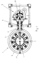
- the device 1 shown in FIGS. 1 and 2 for automatically filling a main magazine 2 of a labeling machine 3 has a carousel-shaped, rotatable magazine carrier 4, on which holding arms 5 are arranged in a circle and at regular intervals from one another.
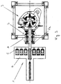
- the device shown in FIG. 3 differs from the device shown in FIGS. 1 and 2 in that the magazine carrier 6 is rectangular and the holding arms 5 are arranged linearly next to one another at regular intervals, the magazine carrier 6 being transverse to the longitudinal axis 7 of the main magazine 2 is movable.
- the holding arms 5 shown in FIGS. 1, 2, 3 each have a cranked upper section 5a, at the tip of which a swiveling device 8 is arranged.
- a storage magazine 9 is fastened to this swiveling device 8 in each case by means of a joint element arranged on its bottom surface 10 and assigned to the ejection opening 11 of the storage magazine 9.
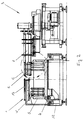
- the storage magazine 9 can be pivoted from its vertically oriented, hanging waiting position W into a horizontally oriented insertion position E by means of the pivoting device 8.
- the corresponding pivoting movement is indicated by arrows P in FIGS. 2.2a, the supply magazine 9 being shown in dashed lines in its hanging waiting position W and in solid lines in its insertion position E in FIG. 2a.
- the holding arms 5 is a, carried by the frame 12 of the device 1, pneumatically in the direction of Main magazine 2 arranged from a waiting position insert plunger 13, the longitudinal axis of which is aligned with the longitudinal axis 7 of the main magazine 2. Its length is dimensioned in its waiting division in such a way that sufficient space remains for the pivoting of the storage magazines 9 in their insertion position E between the insertion plunger 13 and the main magazine 2.
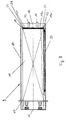
- Each of the storage magazines 9 is box-shaped and has 10 side walls 14 in addition to the bottom surface.
- 10 slide rails 15 are arranged on the bottom surface, which protrude beyond the opening 11 and the front edge of the bottom surface 10. The section of the slide rails 15 protruding beyond the front edge of the bottom surface 10 engages in corresponding recesses in the main magazine 2 in the insertion position E of the storage magazines 9.
- each storage magazine 9 has a rear wall 16 and a plate 17 which is sprung against the rear wall 16 and via which a stack of labels 18 filled in the respective storage magazine is resiliently supported in the waiting position W of the storage container 9.
- This arrangement of the plate 17 enables the stack of labels 18 of different lengths to be filled into the storage container 9, since the spring-loaded support always ensures that the end face 18a of the stack of labels 18 is arranged at a predetermined point in the discharge opening 11 of the storage container 9.
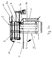
- each storage container 9 is equipped with holding elements 19 which each extend inside the storage container 9 on both sides along a stack of labels 18 filled with a plurality of individual labels and filled into the storage container 9.
- On the Holding elements 19 exert tension springs 20 spring forces.
- the tension springs 20 each extend along the holding elements 19 and are attached at one end to the end 19a of the holding elements 19 assigned to the ejection opening 11 and at the other end to a rear section of the side walls 14.
- the holding elements 19 are designed in the manner of leaf springs and can be resiliently bent at least in the region of their end 19a in the transverse direction to their longitudinal axis. At their end 19a, the holding elements 19 each have projections 21 protruding toward the inside of the storage container 9, which protrude from the end face 18a of the label stack 18 and prevent unwanted escape of individual labels of the label stack 18 from the storage container 9. In addition, at the end 19a of the holding elements 19, a section 22 is formed in a funnel-shaped curve facing outward from the label stack 18.
- the main magazine 2 has a guideway 23 for a label stack 24 inserted into the main magazine 2.
- a guiding element 26 designed as a roller 25 carried by a pin is arranged.
- the inserted label stack 24 is conveyed by conveyor elements 27 in the direction of glue segments 28 of the labeling machine 3.
- the conveying elements 27 are pivotally attached to a conveying device 29 and are each held by a torsion spring 30 in contact with the inserted stack of labels 24.
- the main magazine 2 is also equipped with consumption sensors, not shown, which monitor the consumption of the labels of the label stack 24 inserted into the main magazine 2.
- the consumption sensors report the need to refill the main magazine 2 with a new label stack 18 so early that there is always a sufficient amount of labels in the main magazine 2 to operate the labeling machine 3 without interruption, taking into account the refilling process.
- the device explained above works as follows: As soon as the consumption sensors of the main magazine 2 report that a refilling of the main magazine 2 is necessary, one of the storage containers 9 is conveyed into its pivoting position by means of the magazine carrier 4, in which it is arranged directly in front of the main magazine 2 of the labeling machine 3. The respective holding arm 9 is arranged below the main magazine 2 in a space-saving manner.
- the respective storage container 9 is then pivoted into its insertion position E (FIG. 2a), in which it is aligned horizontally with the main magazine 2.
- the ejection opening 11 of the storage container 9 now lies flush with the insertion opening of the main magazine 2, the sections of the slide rails 15 projecting into the main magazine 2 ensuring that the new stack of labels 18 can be pushed into the main magazine 2 without jolts.
- the slide-in ram 13 moves into the storage magazine 9 and pushes the stack of labels 18 in the direction of the main magazine 2.
- the holding elements 19 are carried along by their projections 21 and exert a force generated by the tension springs 20 on the label stack 18 until the end of the used label stack 24 already in the main magazine 2 is approximately reached. In this position, the funnel-shaped sections 22 of the holding elements 19 meet the roller 25 of the respective guide element 26 (FIGS. 4a, b).
- the further insertion of the label stack 18 into the main magazine 2 has the effect that the funnel-shaped section 22 of the holding elements 19 is guided away from the label stack 18 by the guide element 26 while the holding element 19 is bent in the direction transverse to its longitudinal axis. This bending is accompanied by a pivoting away of the projections 21 of the holding elements 19 from the end face 18a of the label stack 18 (FIGS. 5a, b).
- the conveying elements 27 are pulled out between the stacks of labels 18, 24 in a pivoting movement triggered by the conveying device 29.
- the conveyor device 29 then moves with the conveyor elements 27 to the end of the newly inserted label stack 18, where they pivot behind the label stack 18.
- the label stack 18 can now be conveyed in the main magazine 2 in the direction of the glue segments 28 of the labeling machine 3 (FIGS. 7a, b).
Landscapes
- Labeling Devices (AREA)
- Sheets, Magazines, And Separation Thereof (AREA)
Applications Claiming Priority (2)
| Application Number | Priority Date | Filing Date | Title |
|---|---|---|---|
| DE4417497A DE4417497A1 (de) | 1994-05-19 | 1994-05-19 | Vorrichtung zum automatischen Befüllen des Hauptmagazins einer Etikettiermaschine, sowie in einer derartigen Vorrichtung verwendbares Vorratsmagazin |
| DE4417497 | 1994-05-19 |
Publications (2)
| Publication Number | Publication Date |
|---|---|
| EP0683101A2 true EP0683101A2 (fr) | 1995-11-22 |
| EP0683101A3 EP0683101A3 (fr) | 1996-01-03 |
Family
ID=6518452
Family Applications (1)
| Application Number | Title | Priority Date | Filing Date |
|---|---|---|---|
| EP95107068A Withdrawn EP0683101A2 (fr) | 1994-05-19 | 1995-05-10 | Dispositif pour le remplissage automatique du magasin principal d'une étiqueteuse et magasin utilisable dans un tel dispositif |
Country Status (4)
| Country | Link |
|---|---|
| US (1) | US5569353A (fr) |
| EP (1) | EP0683101A2 (fr) |
| BR (1) | BR9502482A (fr) |
| DE (1) | DE4417497A1 (fr) |
Cited By (1)
| Publication number | Priority date | Publication date | Assignee | Title |
|---|---|---|---|---|
| EP0836999A1 (fr) * | 1996-10-19 | 1998-04-22 | Kronseder, Hermann, Dr.-Ing. E.h. | Dispositif chargeur d'étiquettes dans des étiqueteuses |
Families Citing this family (25)
| Publication number | Priority date | Publication date | Assignee | Title |
|---|---|---|---|---|
| DE19712193C5 (de) * | 1997-03-22 | 2008-06-12 | Khs Ag | Wechselmagazin für Etiketten einer Etikettiermaschine |
| JP3808581B2 (ja) * | 1997-03-25 | 2006-08-16 | 株式会社湯山製作所 | 注射剤払出装置 |
| US6170700B1 (en) | 1998-11-06 | 2001-01-09 | Kalish Canada Inc. | Leaflet dispensing apparatus |
| DE10007089A1 (de) | 2000-02-16 | 2001-08-23 | Focke & Co | Vorrichtung zur Handhabung von Zuschnitten, insbesondere Banderolen für Zigarettenpackungen |
| ITPR20010053A1 (it) * | 2001-08-24 | 2003-02-24 | Sig Alfa Spa | Magazzino etichette, in particolare per macchine etichettatrici. |
| EP1314648B1 (fr) | 2001-11-08 | 2003-06-04 | KOSME S.r.l. | Magasin automatique pour alimenter en étiquettes des étiqueteuses |
| ITBO20040670A1 (it) * | 2004-10-28 | 2005-01-28 | Gd Spa | Unita' di alimentazione di materiale di incarto raggruppato in pile ad una macchina impachettatrice |
| US7704347B2 (en) | 2005-05-27 | 2010-04-27 | Prairie Packaging, Inc. | Reinforced plastic foam cup, method of and apparatus for manufacturing same |
| US7694843B2 (en) | 2005-05-27 | 2010-04-13 | Prairie Packaging, Inc. | Reinforced plastic foam cup, method of and apparatus for manufacturing same |
| US7818866B2 (en) | 2005-05-27 | 2010-10-26 | Prairie Packaging, Inc. | Method of reinforcing a plastic foam cup |
| US7814647B2 (en) | 2005-05-27 | 2010-10-19 | Prairie Packaging, Inc. | Reinforced plastic foam cup, method of and apparatus for manufacturing same |
| US9612369B2 (en) | 2007-08-12 | 2017-04-04 | Toyota Motor Engineering & Manufacturing North America, Inc. | Red omnidirectional structural color made from metal and dielectric layers |
| US9739917B2 (en) | 2007-08-12 | 2017-08-22 | Toyota Motor Engineering & Manufacturing North America, Inc. | Red omnidirectional structural color made from metal and dielectric layers |
| US10870740B2 (en) | 2007-08-12 | 2020-12-22 | Toyota Jidosha Kabushiki Kaisha | Non-color shifting multilayer structures and protective coatings thereon |
| US10048415B2 (en) | 2007-08-12 | 2018-08-14 | Toyota Motor Engineering & Manufacturing North America, Inc. | Non-dichroic omnidirectional structural color |
| US10690823B2 (en) | 2007-08-12 | 2020-06-23 | Toyota Motor Corporation | Omnidirectional structural color made from metal and dielectric layers |
| DE102007062471A1 (de) * | 2007-12-20 | 2009-06-25 | Krones Ag | Vorrichtung und Verfahren zum Aufbringen von Etiketten |
| US8828170B2 (en) | 2010-03-04 | 2014-09-09 | Pactiv LLC | Apparatus and method for manufacturing reinforced containers |
| DE102012101114A1 (de) * | 2012-02-14 | 2013-08-14 | Krones Ag | Vorrichtung zum Bereitstellen von Verbrauchsmaterial |
| US9678260B2 (en) | 2012-08-10 | 2017-06-13 | Toyota Motor Engineering & Manufacturing North America, Inc. | Omnidirectional high chroma red structural color with semiconductor absorber layer |
| US9658375B2 (en) | 2012-08-10 | 2017-05-23 | Toyota Motor Engineering & Manufacturing North America, Inc. | Omnidirectional high chroma red structural color with combination metal absorber and dielectric absorber layers |
| US9664832B2 (en) | 2012-08-10 | 2017-05-30 | Toyota Motor Engineering & Manufacturing North America, Inc. | Omnidirectional high chroma red structural color with combination semiconductor absorber and dielectric absorber layers |
| JP6741586B2 (ja) | 2014-04-01 | 2020-08-19 | トヨタ モーター エンジニアリング アンド マニュファクチャリング ノース アメリカ,インコーポレイティド | 色シフトのない多層構造 |
| US9810824B2 (en) | 2015-01-28 | 2017-11-07 | Toyota Motor Engineering & Manufacturing North America, Inc. | Omnidirectional high chroma red structural colors |
| DE102022101940A1 (de) * | 2022-01-27 | 2023-07-27 | Espera-Werke Gmbh | Verfahren zum Betrieb eines Etikettiersystems |
Citations (3)
| Publication number | Priority date | Publication date | Assignee | Title |
|---|---|---|---|---|
| DE3536294A1 (de) * | 1985-10-11 | 1987-04-16 | Hermann Kronseder | Verfahren und vorrichtung zum austauschen der wechselmagazine einer magazinvorrichtung fuer etiketten in etikettiermaschinen |
| FR2631011A1 (fr) * | 1988-05-04 | 1989-11-10 | Astinfrance Sarl | Procede de transfert d'une pile de produits plats et dispositif de manutention d'une telle pile |
| EP0537823A1 (fr) * | 1991-10-15 | 1993-04-21 | Peter Theel | Dispositif pour alimenter en feuilles de carton une machine de traitement |
Family Cites Families (9)
| Publication number | Priority date | Publication date | Assignee | Title |
|---|---|---|---|---|
| US1536835A (en) * | 1925-05-05 | Ezst t hojbjii pstti | ||
| US2060193A (en) * | 1933-07-21 | 1936-11-10 | Us Rubber Co | Label applying machine |
| US3180521A (en) * | 1963-04-08 | 1965-04-27 | Jo Dee Corp | Rotary dispenser |
| CA1003792A (en) * | 1973-01-25 | 1977-01-18 | Hermann Kronseder | Method and apparatus for tray loading of labels into label magazines |
| BR8102485A (pt) * | 1980-04-30 | 1982-01-05 | Jagenberg Werke Ag | Dispositivo para trocar caixas de deposito de etiquetas em maquinas de rotular |
| BR8207560A (pt) * | 1982-02-16 | 1983-10-25 | Jagenberg Ag | Estacao de etiquetagem para objetos como garrafas |
| DE3402514A1 (de) * | 1984-01-26 | 1985-08-01 | Focke & Co, 2810 Verden | Vorrichtung zum verpacken von gegenstaenden, insbesondere zigaretten |
| EP0190633A1 (fr) * | 1985-02-02 | 1986-08-13 | Hermann Kronseder | Dispositif chargeur d'étiquettes pour étiqueteuse et procédé pour échanger des magasins de recharge |
| DE3630925C3 (de) * | 1986-09-11 | 1988-03-24 | Hermann Kronseder | Magazinvorrichtung fuer etiketten in etikettiermaschinen |
-
1994
- 1994-05-19 DE DE4417497A patent/DE4417497A1/de not_active Withdrawn
-
1995
- 1995-05-10 EP EP95107068A patent/EP0683101A2/fr not_active Withdrawn
- 1995-05-19 US US08/444,621 patent/US5569353A/en not_active Expired - Fee Related
- 1995-05-19 BR BR9502482A patent/BR9502482A/pt not_active Application Discontinuation
Patent Citations (3)
| Publication number | Priority date | Publication date | Assignee | Title |
|---|---|---|---|---|
| DE3536294A1 (de) * | 1985-10-11 | 1987-04-16 | Hermann Kronseder | Verfahren und vorrichtung zum austauschen der wechselmagazine einer magazinvorrichtung fuer etiketten in etikettiermaschinen |
| FR2631011A1 (fr) * | 1988-05-04 | 1989-11-10 | Astinfrance Sarl | Procede de transfert d'une pile de produits plats et dispositif de manutention d'une telle pile |
| EP0537823A1 (fr) * | 1991-10-15 | 1993-04-21 | Peter Theel | Dispositif pour alimenter en feuilles de carton une machine de traitement |
Cited By (1)
| Publication number | Priority date | Publication date | Assignee | Title |
|---|---|---|---|---|
| EP0836999A1 (fr) * | 1996-10-19 | 1998-04-22 | Kronseder, Hermann, Dr.-Ing. E.h. | Dispositif chargeur d'étiquettes dans des étiqueteuses |
Also Published As
| Publication number | Publication date |
|---|---|
| EP0683101A3 (fr) | 1996-01-03 |
| US5569353A (en) | 1996-10-29 |
| DE4417497A1 (de) | 1995-11-23 |
| BR9502482A (pt) | 1995-12-19 |
Similar Documents
| Publication | Publication Date | Title |
|---|---|---|
| EP0683101A2 (fr) | Dispositif pour le remplissage automatique du magasin principal d'une étiqueteuse et magasin utilisable dans un tel dispositif | |
| EP0222344B1 (fr) | Dispositif à tester et à trier des composants électroniques | |
| EP0941654B1 (fr) | Outil pour appliquer des marques d'oreille | |
| DE3688484T2 (de) | Einrichtung zum zufuehren von bauteilen. | |
| CH454010A (de) | Vorrichtung zum Einlegen von auf einer Zuführeinrichtung ausgerichteten Süsswarenstücken in Verpackungen | |
| DE69500571T2 (de) | Verbesserte Speisevorrichtung für elektronische Komponenten | |
| DE3221620A1 (de) | Vorrichtung zum anbringen von komponenten | |
| EP0344763B1 (fr) | Magasin à bande pour manipulateurs de SMD | |
| DE3002250C2 (de) | Vorrichtung zum Bereitstellen von Etiketten an einer Etikettiermaschine | |
| DE2655040C3 (de) | Munzenausgabegerat | |
| DE3825273A1 (de) | Spulentransporteinrichtung mit auskragendem dorn | |
| DE3712087C2 (fr) | ||
| DE3929405C2 (de) | Vorrichtung für die Zuführung von Textilhülsen | |
| DE4344744A1 (de) | Vorrichtung zum Einbringen von Verpackungen in Verpackungsbehälter | |
| DE4102899A1 (de) | Automat zum zusammenbau von scharnierteilen | |
| DE2850214A1 (de) | Ausgabevorrichtung fuer verkaufsautomaten u.dgl. | |
| EP3718711A2 (fr) | Procédé de fonctionnement d'un robot, tête d'outil pour un robot ainsi que ligne d'usinage dotée d'un robot | |
| DE3429285A1 (de) | Vorrichtung zum umhuellen von bloecken | |
| DE19926713B4 (de) | Vorrichtung zur Handhabung von Banderolen | |
| DE1218254B (de) | Vorrichtung zum Beschicken einer Rohrbiegemaschine | |
| DE4328359A1 (de) | Halterung für plattenförmige Gegenstände, insbesondere Leiterplatten sowie Entnahme- und Beschickungseinrichtung für diese Halterung | |
| DE3536294C2 (fr) | ||
| DE3409395A1 (de) | Vorrichtung zum automatischen legen von distanzlatten | |
| DE19712193C5 (de) | Wechselmagazin für Etiketten einer Etikettiermaschine | |
| DE3040195A1 (de) | Ausrichtvorrichtung fuer bandkassetten |
Legal Events
| Date | Code | Title | Description |
|---|---|---|---|
| PUAI | Public reference made under article 153(3) epc to a published international application that has entered the european phase |
Free format text: ORIGINAL CODE: 0009012 |
|
| PUAL | Search report despatched |
Free format text: ORIGINAL CODE: 0009013 |
|
| AK | Designated contracting states |
Kind code of ref document: A2 Designated state(s): AT CH DE FR GB IT LI |
|
| AK | Designated contracting states |
Kind code of ref document: A3 Designated state(s): AT CH DE FR GB IT LI |
|
| 17P | Request for examination filed |
Effective date: 19960129 |
|
| GRAG | Despatch of communication of intention to grant |
Free format text: ORIGINAL CODE: EPIDOS AGRA |
|
| GRAG | Despatch of communication of intention to grant |
Free format text: ORIGINAL CODE: EPIDOS AGRA |
|
| GRAG | Despatch of communication of intention to grant |
Free format text: ORIGINAL CODE: EPIDOS AGRA |
|
| 17Q | First examination report despatched |
Effective date: 19960923 |
|
| GRAH | Despatch of communication of intention to grant a patent |
Free format text: ORIGINAL CODE: EPIDOS IGRA |
|
| RAP3 | Party data changed (applicant data changed or rights of an application transferred) |
Owner name: KHS ETI-TEC MASCHINENBAU GMBH |
|
| STAA | Information on the status of an ep patent application or granted ep patent |
Free format text: STATUS: THE APPLICATION IS DEEMED TO BE WITHDRAWN |
|
| 18D | Application deemed to be withdrawn |
Effective date: 19970301 |