EP0683101A2 - Device for automatically filling the main magazine of a labelling machine and magazine for use in such a device - Google Patents
Device for automatically filling the main magazine of a labelling machine and magazine for use in such a device Download PDFInfo
- Publication number
- EP0683101A2 EP0683101A2 EP95107068A EP95107068A EP0683101A2 EP 0683101 A2 EP0683101 A2 EP 0683101A2 EP 95107068 A EP95107068 A EP 95107068A EP 95107068 A EP95107068 A EP 95107068A EP 0683101 A2 EP0683101 A2 EP 0683101A2
- Authority
- EP
- European Patent Office
- Prior art keywords
- magazine
- stack
- labels
- storage
- label stack
- Prior art date
- Legal status (The legal status is an assumption and is not a legal conclusion. Google has not performed a legal analysis and makes no representation as to the accuracy of the status listed.)
- Withdrawn
Links
Images


Classifications
-
- B—PERFORMING OPERATIONS; TRANSPORTING
- B65—CONVEYING; PACKING; STORING; HANDLING THIN OR FILAMENTARY MATERIAL
- B65C—LABELLING OR TAGGING MACHINES, APPARATUS, OR PROCESSES
- B65C9/00—Details of labelling machines or apparatus
- B65C9/08—Label feeding
- B65C9/10—Label magazines
- B65C9/105—Storage arrangements including a plurality of magazines
-
- Y—GENERAL TAGGING OF NEW TECHNOLOGICAL DEVELOPMENTS; GENERAL TAGGING OF CROSS-SECTIONAL TECHNOLOGIES SPANNING OVER SEVERAL SECTIONS OF THE IPC; TECHNICAL SUBJECTS COVERED BY FORMER USPC CROSS-REFERENCE ART COLLECTIONS [XRACs] AND DIGESTS
- Y10—TECHNICAL SUBJECTS COVERED BY FORMER USPC
- Y10T—TECHNICAL SUBJECTS COVERED BY FORMER US CLASSIFICATION
- Y10T156/00—Adhesive bonding and miscellaneous chemical manufacture
- Y10T156/17—Surface bonding means and/or assemblymeans with work feeding or handling means
- Y10T156/1702—For plural parts or plural areas of single part
- Y10T156/1744—Means bringing discrete articles into assembled relationship
- Y10T156/1763—Magazine stack directly contacting separate work
-
- Y—GENERAL TAGGING OF NEW TECHNOLOGICAL DEVELOPMENTS; GENERAL TAGGING OF CROSS-SECTIONAL TECHNOLOGIES SPANNING OVER SEVERAL SECTIONS OF THE IPC; TECHNICAL SUBJECTS COVERED BY FORMER USPC CROSS-REFERENCE ART COLLECTIONS [XRACs] AND DIGESTS
- Y10—TECHNICAL SUBJECTS COVERED BY FORMER USPC
- Y10T—TECHNICAL SUBJECTS COVERED BY FORMER US CLASSIFICATION
- Y10T156/00—Adhesive bonding and miscellaneous chemical manufacture
- Y10T156/17—Surface bonding means and/or assemblymeans with work feeding or handling means
- Y10T156/1702—For plural parts or plural areas of single part
- Y10T156/1744—Means bringing discrete articles into assembled relationship
- Y10T156/1768—Means simultaneously conveying plural articles from a single source and serially presenting them to an assembly station
- Y10T156/1771—Turret or rotary drum-type conveyor
- Y10T156/1773—For flexible sheets
-
- Y—GENERAL TAGGING OF NEW TECHNOLOGICAL DEVELOPMENTS; GENERAL TAGGING OF CROSS-SECTIONAL TECHNOLOGIES SPANNING OVER SEVERAL SECTIONS OF THE IPC; TECHNICAL SUBJECTS COVERED BY FORMER USPC CROSS-REFERENCE ART COLLECTIONS [XRACs] AND DIGESTS
- Y10—TECHNICAL SUBJECTS COVERED BY FORMER USPC
- Y10T—TECHNICAL SUBJECTS COVERED BY FORMER US CLASSIFICATION
- Y10T156/00—Adhesive bonding and miscellaneous chemical manufacture
- Y10T156/17—Surface bonding means and/or assemblymeans with work feeding or handling means
- Y10T156/1702—For plural parts or plural areas of single part
- Y10T156/1744—Means bringing discrete articles into assembled relationship
- Y10T156/1776—Means separating articles from bulk source
- Y10T156/1778—Stacked sheet source
- Y10T156/178—Rotary or pivoted picker
Definitions
- the invention relates to a device for automatically filling the main magazine of a labeling machine with a label stack consisting of a plurality of individual labels, which can be inserted from a storage magazine by means of a feed device into the main magazine via its insertion opening.
- the invention also relates to a storage magazine which can be used in such devices.
- Devices and storage magazines of the aforementioned type make it possible to operate labeling machines without interruption over a long period of time without the need for an operator to refill the main magazine with new labels.
- a device of the type mentioned is known for example from German patent DE 35 36 294 C2.
- the storage magazines are arranged parallel to one another on a table-shaped slideway, via which they are conveyed behind the main magazine of the associated labeling machine by means of a feed device.
- the end faces of the stack of labels contained in the storage magazines lie against a guide rail during the advancement of the storage magazines, which prevent the labels from falling out during the movement. This rail is withdrawn when the respective storage magazine has reached the filling position behind the main magazine.
- German patent DE 36 30 925 C2 In order to prevent individual labels of the label stack from falling out in the storage magazine, it is known from German patent DE 36 30 925 C2 to provide releasable adhesive strips by means of which the end face of the respective first label of the stack of labels contained in the storage magazine is connected to the walls of the storage magazine are. These adhesive strips are removed immediately before the stack of labels is inserted into the main magazine. The use of adhesive strips complicates the handling of the known storage magazines when inserting the stack of labels into the main magazine.
- the advantage of the known device is that because of the table-shaped arrangement of the storage magazines and the associated low overall height, it is possible to arrange several refill devices one above the other, as is often required for multiple labeling of bottles. For this purpose, however, a large space requirement for the sliding surface must be accepted, which increases the more storage magazines are to be stored on the sliding surface.
- Another disadvantage of the known device is that the large sliding surface makes access to the feed mechanism arranged below it difficult.
- it has been shown in the practical testing of the known device that malfunctions frequently occur during the insertion of a new stack of labels into the main magazine.
- German patent DE 36 30 925 C2 In order to prevent individual labels of the label stack from falling out in the storage magazine, it is known from German patent DE 36 30 925 C2 to provide detachable adhesive strips, by means of which the end face of the first label of the label stack contained in the storage magazine with the walls of the Storage magazine are connected. These adhesive strips are removed immediately before the stack of labels is inserted into the main magazine. The use of adhesive strips complicates the handling of the known storage magazines when inserting the stack of labels into the main magazine.
- the object of the invention is to reduce the space required for a device of the type mentioned, to simplify the automatic refilling of the main magazine and at the same time to reduce the risk of a malfunction of the insertion process.
- the storage magazine can be pivoted from a waiting position into an insertion position, in which its extension opening lies against the insertion opening of the main magazine.
- the supply magazines are in a waiting position, as long as the main magazine is still sufficiently filled, from which they are pivoted into the filling position to fill the main magazine with new labels.
- the pivotability of the storage magazines enables them to be held in a waiting position angled relative to the conveying surface of the main magazine. In this way, the footprint required for the refill device can be reduced. This applies in particular if the storage magazines are arranged hanging in their waiting position. In this case, individual labels are prevented from falling out of the storage container by their own weight.
- the pivotability of the storage magazines also enables the storage magazines to be directly at the insertion opening of the main magazine swivel in so that the new stack of labels can be transferred smoothly into the main magazine and is always guided during its transfer into the main magazine. This reduces the risk of the insertion process being disrupted by slipping individual labels.
- Good operability with a simultaneously further reduced space requirement for the device according to the invention can be achieved in that several storage magazines of the same type are held by the arms of a magazine carrier, by means of which they can be conveyed into their pivoted position.
- This makes it possible, for example, to arrange the storage magazines on a carousel-shaped magazine carrier on which they can be loaded and monitored without any problems.
- Other arrangements of the storage magazines on the magazine carrier, in particular a linear arrangement of the magazines next to one another, are conceivable.
- the magazine carrier conveys the storage magazines to their swivel position in the area of the main magazine, where they are swiveled from the waiting position to the insertion position.
- a particularly simple mechanism for pivoting the storage magazines can be used when the storage magazines hang on the arms of the magazine carrier.
- a further improvement in the smooth transition of the label stack from the respective storage magazine into the main magazine can be achieved in that the storage magazines have projections in the region of their ejection opening at least on the surface on which the labels are supported during insertion into the main magazine engage in corresponding recesses in the main magazine in the inserted position.
- An unwanted exit of the labels from the label stack during the pivoting of the respective storage magazine or during insertion can be prevented by holding elements in the waiting position and at least over part of the distance covered during insertion of the label stack into the main magazine Prevent stack of labels from the storage magazine and that the holding elements then automatically release the stack of labels.
- holding elements both the maintenance of the supply magazines and during their pivoting and in the critical phase at the start of the insertion of the stack of labels into the main magazine, secure holding of the stack of labels and thus trouble-free pivoting and insertion are guaranteed at all times.
- the cohesion of the label stack which favors a trouble-free insertion of the label stack into the main magazine, with reduced space requirement during the insertion phase, can also be achieved by a storage magazine for a device for automatically filling a main magazine of a labeling machine with one consisting of a large number of individual labels Label stack, the storage magazine being equipped with holding means which prevent the label stack from falling apart before it is pushed into the main magazine, thereby ensuring that the holding means can be pushed into the main magazine together with the respective label stack so that the holding elements during the insertion of the label stack in the main magazine on the front of the label stack a holding force opposite to the insertion force on the Exercise stack of labels and that the holding elements automatically swing away from the end face of the stack of labels immediately before reaching the end of the insertion path.
- the stack of labels is prevented from falling apart until it reaches the end of its insertion path and forms an easily controllable unit during insertion.
- storage magazines not only is the insertion of the stack of labels favored, but also space is saved which is required in the known devices for additional securing elements, by means of which a malfunction by, for example, slipping individual labels is to be prevented, at least when the storage container is being brought up to the main magazine.
- the holding elements are designed in the manner of leaf springs, which are arranged axially parallel to and parallel to the longitudinal axis of the label stack and can be bent in the transverse direction to the longitudinal axis of the label stack, they can simultaneously serve for lateral guidance of the label stack.
- the automatic pivoting away of the holding elements from the end face of the stack of labels can be accomplished in a simple manner.
- the holding elements can be pivoted away from the end face of the stack of labels by a guide element arranged at the end of the insertion path of the holding elements.
- the holding elements should be assigned to the end face of the stack of labels Tip have at least one protruding from the label stack, in particular funnel-shaped rounded section, which causes the holding element to pivot away from the end face of the label stack when it hits the guide element, wherein the guide element can consist of a roller carried by a pin.
- the holding elements can be retracted into their starting position by means of tension springs, one end of each of which is fastened to one of the walls of the storage magazine.
- tension springs can exert the force necessary for holding the stack of labels together during their insertion into the main magazine via the holding elements.
- the springs ensure that the holding elements are automatically retracted into their starting position after they have been pivoted away from the end face of the stack of labels, so that the respective storage magazine can be swiveled back into the waiting division without problems after the insertion is completed and filled again.
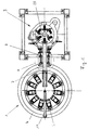
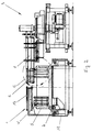
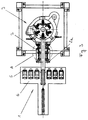
- the device 1 shown in FIGS. 1 and 2 for automatically filling a main magazine 2 of a labeling machine 3 has a carousel-shaped, rotatable magazine carrier 4, on which holding arms 5 are arranged in a circle and at regular intervals from one another.
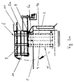
- the device shown in FIG. 3 differs from the device shown in FIGS. 1 and 2 in that the magazine carrier 6 is rectangular and the holding arms 5 are arranged linearly next to one another at regular intervals, the magazine carrier 6 being transverse to the longitudinal axis 7 of the main magazine 2 is movable.
- the holding arms 5 shown in FIGS. 1, 2, 3 each have a cranked upper section 5a, at the tip of which a swiveling device 8 is arranged.
- a storage magazine 9 is fastened to this swiveling device 8 in each case by means of a joint element arranged on its bottom surface 10 and assigned to the ejection opening 11 of the storage magazine 9.
- the storage magazine 9 can be pivoted from its vertically oriented, hanging waiting position W into a horizontally oriented insertion position E by means of the pivoting device 8.
- the corresponding pivoting movement is indicated by arrows P in FIGS. 2.2a, the supply magazine 9 being shown in dashed lines in its hanging waiting position W and in solid lines in its insertion position E in FIG. 2a.
- the holding arms 5 is a, carried by the frame 12 of the device 1, pneumatically in the direction of Main magazine 2 arranged from a waiting position insert plunger 13, the longitudinal axis of which is aligned with the longitudinal axis 7 of the main magazine 2. Its length is dimensioned in its waiting division in such a way that sufficient space remains for the pivoting of the storage magazines 9 in their insertion position E between the insertion plunger 13 and the main magazine 2.
- Each of the storage magazines 9 is box-shaped and has 10 side walls 14 in addition to the bottom surface.
- 10 slide rails 15 are arranged on the bottom surface, which protrude beyond the opening 11 and the front edge of the bottom surface 10. The section of the slide rails 15 protruding beyond the front edge of the bottom surface 10 engages in corresponding recesses in the main magazine 2 in the insertion position E of the storage magazines 9.
- each storage magazine 9 has a rear wall 16 and a plate 17 which is sprung against the rear wall 16 and via which a stack of labels 18 filled in the respective storage magazine is resiliently supported in the waiting position W of the storage container 9.
- This arrangement of the plate 17 enables the stack of labels 18 of different lengths to be filled into the storage container 9, since the spring-loaded support always ensures that the end face 18a of the stack of labels 18 is arranged at a predetermined point in the discharge opening 11 of the storage container 9.
- each storage container 9 is equipped with holding elements 19 which each extend inside the storage container 9 on both sides along a stack of labels 18 filled with a plurality of individual labels and filled into the storage container 9.
- On the Holding elements 19 exert tension springs 20 spring forces.
- the tension springs 20 each extend along the holding elements 19 and are attached at one end to the end 19a of the holding elements 19 assigned to the ejection opening 11 and at the other end to a rear section of the side walls 14.
- the holding elements 19 are designed in the manner of leaf springs and can be resiliently bent at least in the region of their end 19a in the transverse direction to their longitudinal axis. At their end 19a, the holding elements 19 each have projections 21 protruding toward the inside of the storage container 9, which protrude from the end face 18a of the label stack 18 and prevent unwanted escape of individual labels of the label stack 18 from the storage container 9. In addition, at the end 19a of the holding elements 19, a section 22 is formed in a funnel-shaped curve facing outward from the label stack 18.
- the main magazine 2 has a guideway 23 for a label stack 24 inserted into the main magazine 2.
- a guiding element 26 designed as a roller 25 carried by a pin is arranged.
- the inserted label stack 24 is conveyed by conveyor elements 27 in the direction of glue segments 28 of the labeling machine 3.
- the conveying elements 27 are pivotally attached to a conveying device 29 and are each held by a torsion spring 30 in contact with the inserted stack of labels 24.
- the main magazine 2 is also equipped with consumption sensors, not shown, which monitor the consumption of the labels of the label stack 24 inserted into the main magazine 2.
- the consumption sensors report the need to refill the main magazine 2 with a new label stack 18 so early that there is always a sufficient amount of labels in the main magazine 2 to operate the labeling machine 3 without interruption, taking into account the refilling process.
- the device explained above works as follows: As soon as the consumption sensors of the main magazine 2 report that a refilling of the main magazine 2 is necessary, one of the storage containers 9 is conveyed into its pivoting position by means of the magazine carrier 4, in which it is arranged directly in front of the main magazine 2 of the labeling machine 3. The respective holding arm 9 is arranged below the main magazine 2 in a space-saving manner.
- the respective storage container 9 is then pivoted into its insertion position E (FIG. 2a), in which it is aligned horizontally with the main magazine 2.
- the ejection opening 11 of the storage container 9 now lies flush with the insertion opening of the main magazine 2, the sections of the slide rails 15 projecting into the main magazine 2 ensuring that the new stack of labels 18 can be pushed into the main magazine 2 without jolts.
- the slide-in ram 13 moves into the storage magazine 9 and pushes the stack of labels 18 in the direction of the main magazine 2.
- the holding elements 19 are carried along by their projections 21 and exert a force generated by the tension springs 20 on the label stack 18 until the end of the used label stack 24 already in the main magazine 2 is approximately reached. In this position, the funnel-shaped sections 22 of the holding elements 19 meet the roller 25 of the respective guide element 26 (FIGS. 4a, b).
- the further insertion of the label stack 18 into the main magazine 2 has the effect that the funnel-shaped section 22 of the holding elements 19 is guided away from the label stack 18 by the guide element 26 while the holding element 19 is bent in the direction transverse to its longitudinal axis. This bending is accompanied by a pivoting away of the projections 21 of the holding elements 19 from the end face 18a of the label stack 18 (FIGS. 5a, b).
- the conveying elements 27 are pulled out between the stacks of labels 18, 24 in a pivoting movement triggered by the conveying device 29.
- the conveyor device 29 then moves with the conveyor elements 27 to the end of the newly inserted label stack 18, where they pivot behind the label stack 18.
- the label stack 18 can now be conveyed in the main magazine 2 in the direction of the glue segments 28 of the labeling machine 3 (FIGS. 7a, b).
Abstract
Description
Die Erfindung betrifft eine Vorrichtung zum automatischen Befüllen des Hauptmagazins einer Etikettiermaschine mit einem aus einer Vielzahl von Einzeletiketten bestehenden Etikettenstapel, welcher aus einem Vorratsmagazin mittels einer Vorschubeinrichtung in das Hauptmagazin über dessen Einschuböffnung einschiebbar ist. Darüber hinaus betrifft die Erfindung auch ein Vorratsmagazin, welches in derartigen Vorrichtungen einsetzbar ist.The invention relates to a device for automatically filling the main magazine of a labeling machine with a label stack consisting of a plurality of individual labels, which can be inserted from a storage magazine by means of a feed device into the main magazine via its insertion opening. In addition, the invention also relates to a storage magazine which can be used in such devices.
Vorrichtungen und Vorratsmagazine der vorstehend genannten Art ermöglichen es, Etikettiermaschinen über einen langen Zeitraum Unterbrechungsfrei zu betreiben, ohne daß eine Bedienungsperson zum Nachfüllen des Hauptmagazins mit neuen Etiketten erforderlich ist.Devices and storage magazines of the aforementioned type make it possible to operate labeling machines without interruption over a long period of time without the need for an operator to refill the main magazine with new labels.
Eine Vorrichtung der eingangs genannten Art ist beispielsweise aus der deutschen Patentschrift DE 35 36 294 C2 bekannt. Bei der bekannten Vorrichtung sind die Vorratsmagazine parallel zueinander auf einer tischförmigen Gleitbahn angeordnet, über die sie mittels einer Vorschubeinrichtung hinter das Hauptmagazin der zugehörigen Etikettiermaschine gefördert werden. Dabei liegen die Stirnseiten der in den Vorratsmagazinen enthaltenen Etikettenstapel wahrend des Vorschiebens der Vorratsmagazine an einer Führungsschiene an, die ein Herausfallen der Etiketten während des Verschiebens verhindern. Diese Schiene wird zurückgezogen, wenn das jeweilige Vorratsmagazin die Einfüllstellung hinter dem Hauptmagazin erreicht hat.A device of the type mentioned is known for example from German patent DE 35 36 294 C2. In the known device, the storage magazines are arranged parallel to one another on a table-shaped slideway, via which they are conveyed behind the main magazine of the associated labeling machine by means of a feed device. The end faces of the stack of labels contained in the storage magazines lie against a guide rail during the advancement of the storage magazines, which prevent the labels from falling out during the movement. This rail is withdrawn when the respective storage magazine has reached the filling position behind the main magazine.
Um ein Herausfallen von Einzeletiketten des Etikettenstapels in dem Vorratsmagazin zu verhindern, ist es aus der deutschen Patentschrift DE 36 30 925 C2 bekannt, lösbare Klebstreifen vorzusehen, über die die Stirnseite des jeweils ersten Etiketts des in dem Vorratsmagazin enthaltenen Etikettenstapels mit den wanden des Vorratsmagazins verbunden sind. Diese Klebstreifen werden unmittelbar vor dem Einschieben des Etikettenstapels in das Hauptmagazin entfernt. Die Verwendung von Klebstreifen erschwert die Handhabung der bekannten Vorratsmagazine beim Einführen des Etikettenstapels in das Hauptmagazin.In order to prevent individual labels of the label stack from falling out in the storage magazine, it is known from German patent DE 36 30 925 C2 to provide releasable adhesive strips by means of which the end face of the respective first label of the stack of labels contained in the storage magazine is connected to the walls of the storage magazine are. These adhesive strips are removed immediately before the stack of labels is inserted into the main magazine. The use of adhesive strips complicates the handling of the known storage magazines when inserting the stack of labels into the main magazine.
Der Vorteil der bekannten Vorrichtung liegt darin, daß es bei ihr wegen der tischförmigen Anordnung der Vorratsmagazine und ihrer damit einhergehenden geringen Bauhöhe möglich ist, mehrere Nachfüllvorrichtungen übereinander anzuordnen, wie es bei einer Mehrfachetikettierung von Flaschen häufig erforderlich ist. Hierzu muß jedoch jeweils ein großer Raumbedarf für die Gleitfläche in Kauf genommen werden, der umso größer wird, je mehr Vorratsmagazine auf der Gleitfläche bevorratet werden sollen. Ein weiterer Nachteil der bekannten Vorrichtung liegt darin, daß die große Gleitfläche den Zugang zu der unter ihr angeordneten Vorschubmechanik erschwert. Zudem hat es sich bei der praktischen Erprobung der bekannten Vorrichtung gezeigt, daß es während des Einschiebens eines neuen Etikettenstapels in das Hauptmagazin häufig zu Störungen kommt.The advantage of the known device is that because of the table-shaped arrangement of the storage magazines and the associated low overall height, it is possible to arrange several refill devices one above the other, as is often required for multiple labeling of bottles. For this purpose, however, a large space requirement for the sliding surface must be accepted, which increases the more storage magazines are to be stored on the sliding surface. Another disadvantage of the known device is that the large sliding surface makes access to the feed mechanism arranged below it difficult. In addition, it has been shown in the practical testing of the known device that malfunctions frequently occur during the insertion of a new stack of labels into the main magazine.
Um ein Herausfallen von Einzeletiketten des Etikettenstapels in dem Vorratsmagazin zu verhindern, ist es aus der deutschen Patentschrift DE 36 30 925 C2 bekannt, lösbare Klebstreifen vorzusehen, über die die Stirnseite des jeweils ersten Etiketts des in dem Vorratsmagazin enthaltenen Etikettenstapels mit den Wänden des Vorratsmagazins verbunden sind. Diese Klebstreifen werden unmittelbar vor dem Einschieben des Etikettenstapels in das Hauptmagazin entfernt. Die Verwendung von Klebstreifen erschwert die Handhabung der bekannten Vorratsmagazine beim Einführen des Etikettenstapels in das Hauptmagazin.In order to prevent individual labels of the label stack from falling out in the storage magazine, it is known from German patent DE 36 30 925 C2 to provide detachable adhesive strips, by means of which the end face of the first label of the label stack contained in the storage magazine with the walls of the Storage magazine are connected. These adhesive strips are removed immediately before the stack of labels is inserted into the main magazine. The use of adhesive strips complicates the handling of the known storage magazines when inserting the stack of labels into the main magazine.
Die Aufgabe der Erfindung besteht darin, den Raumbedarf für eine Vorrichtung der eingangs genannten Art zu verringern, dabei das automatische Nachfüllen des Hauptmagazins zu vereinfachen und gleichzeitig die Gefahr einer Störung des Einschiebevorgangs zu vermindern.The object of the invention is to reduce the space required for a device of the type mentioned, to simplify the automatic refilling of the main magazine and at the same time to reduce the risk of a malfunction of the insertion process.
Diese Aufgabe wird erfindungsgemäß dadurch gelöst, daß das Vorratsmagazin aus einer Wartestellung in eine Einschubstellung schwenkbar ist, in der seine Ausschuböffnung an der Einschuböffnung des Hauptmagazins anliegt. Gemäß der Erfindung befinden sich die Vorratsmagazine solange das Hauptmagazin noch ausreichend befüllt ist in einer Wartestellung, aus der heraus sie zum Befüllen des Hauptmagazins mit neuen Etiketten in die Einfüllstellung geschwenkt werden. Die Verschwenkbarkeit der Vorratsmagazine ermöglicht es, diese in einer gegenüber der Förderfläche des Hauptmagazins angewinkelten Warteposition zu halten. Auf diese Weise läßt sich die erforderliche Stellfläche für die Nachfüllvorrichtung verringern. Dies gilt insbesondere dann, wenn die Vorratsmagazine in ihrer Wartestellung hängend angeordnet sind. In diesem Fall wird ein Herausfallen von Einzeletiketten aus dem Vorratsbehälter schon durch deren Eigengewicht verhindert. Dies gilt insbesondere dann, wenn bei horizontaler Ausrichtung des Hauptmagazins das Vorratsmagazin in seiner Wartestellung vertikal ausgerichtet ist. Die Verschwenkbarkeit der Vorratsmagazine ermöglicht es darüber hinaus, die Vorratsmagazine unmittelbar an die Einschuböffnung des Hauptmagazin heranzuschwenken, so daß der neue Etikettenstapel stoßfrei in das Hauptmagazin überführt werden kann und während seiner Überführung in das Hauptmagazin stets geführt ist. Dies verringert die Gefahr einer Störung des Einschubvorganges durch verrutschende Einzeletiketten.This object is achieved in that the storage magazine can be pivoted from a waiting position into an insertion position, in which its extension opening lies against the insertion opening of the main magazine. According to the invention, the supply magazines are in a waiting position, as long as the main magazine is still sufficiently filled, from which they are pivoted into the filling position to fill the main magazine with new labels. The pivotability of the storage magazines enables them to be held in a waiting position angled relative to the conveying surface of the main magazine. In this way, the footprint required for the refill device can be reduced. This applies in particular if the storage magazines are arranged hanging in their waiting position. In this case, individual labels are prevented from falling out of the storage container by their own weight. This applies in particular if the supply magazine is oriented vertically in its waiting position when the main magazine is aligned horizontally. The pivotability of the storage magazines also enables the storage magazines to be directly at the insertion opening of the main magazine swivel in so that the new stack of labels can be transferred smoothly into the main magazine and is always guided during its transfer into the main magazine. This reduces the risk of the insertion process being disrupted by slipping individual labels.
Eine gute Bedienbarkeit bei gleichzeitig weiter verringertem Raumbedarf für die erfindungsgemäße Vorrichtung kann dadurch erreicht werden, daß mehrere gleichartige Vorratsmagazine von Armen eines Magazinträgers gehalten sind, mittels dessen sie in ihre Schwenkposition förderbar sind. Dies ermöglicht es beispielsweise, die Vorratsmagazine auf einem karusselförmigen Magazinträger anzuordnen, auf dem sie problemlos beladen und überwacht werden können. Andere Anordnungen der Vorratsmagazine auf dem Magazinträger, insbesondere eine lineare Anordnung der Magazine nebeneinander, sind denkbar. Der Magazinträger fördert dabei die Vorratsmagazine jeweils bei Bedarf in ihre Schwenkposition im Bereich des Hauptmagazins, wo sie aus der Wartestellung in die Einschubstellung geschwenkt werden. Ein besonders einfacher Mechanismus zum Verschwenken der Vorratsmagazine kann dann benutzt werden, wenn die Vorratsmagazine an den Armen des Magazinträgers hängen.Good operability with a simultaneously further reduced space requirement for the device according to the invention can be achieved in that several storage magazines of the same type are held by the arms of a magazine carrier, by means of which they can be conveyed into their pivoted position. This makes it possible, for example, to arrange the storage magazines on a carousel-shaped magazine carrier on which they can be loaded and monitored without any problems. Other arrangements of the storage magazines on the magazine carrier, in particular a linear arrangement of the magazines next to one another, are conceivable. The magazine carrier conveys the storage magazines to their swivel position in the area of the main magazine, where they are swiveled from the waiting position to the insertion position. A particularly simple mechanism for pivoting the storage magazines can be used when the storage magazines hang on the arms of the magazine carrier.
Eine weitere Verbesserung des stoßfreien Übergangs des Etikettenstapels von dem jeweiligen Vorratsmagazin in das Hauptmagazin kann dadurch erreicht werden, daß die Vorratsmagazine mindestens an der Fläche, an der die Etiketten während des Einschiebens in das Hauptmagazin abgestutzt sind, im Bereich ihrer Ausschuböffnung jeweils Vorsprünge aufweisen, die in der Einschubstellung in entsprechende Ausnehmungen des Hauptmagazins eingreifen.A further improvement in the smooth transition of the label stack from the respective storage magazine into the main magazine can be achieved in that the storage magazines have projections in the region of their ejection opening at least on the surface on which the labels are supported during insertion into the main magazine engage in corresponding recesses in the main magazine in the inserted position.
Ein ungewolltes Austritten der Etiketten aus dem Etikettenstapel während des Verschwenkens des jeweiligen Vorratsmagazins oder wahrend des Einschiebens kann dadurch verhindert werden, daß Halteelemente in der wartestellung und zumindest über einen Teil der wahrend des Einschiebens des Etikettenstapels in das Hauptmagazin zurückgelegten Strecke einen ungewollten Austritt der Etiketten des Etikettenstapels aus dem Vorratsmagazin verhindern und daß die Halteelemente anschließend selbsttätig den Etikettenstapel freigeben. Bei Verwendung derartiger Halteelemente ist sowohl während des Wartens der Vorratsmagazine als auch während ihres Verschwenkens sowie in der kritischen Phase bei Beginn des Einschiebens des Etikettenstapels in das Hauptmagazin ein sicherer Zusammenhalt des Etikettenstapels und damit ein störungsfreies Verschwenken und Einschieben jederzeit gewährleistet.An unwanted exit of the labels from the label stack during the pivoting of the respective storage magazine or during insertion can be prevented by holding elements in the waiting position and at least over part of the distance covered during insertion of the label stack into the main magazine Prevent stack of labels from the storage magazine and that the holding elements then automatically release the stack of labels. When such holding elements are used, both the maintenance of the supply magazines and during their pivoting and in the critical phase at the start of the insertion of the stack of labels into the main magazine, secure holding of the stack of labels and thus trouble-free pivoting and insertion are guaranteed at all times.
Gemäß einer alternativen Lösung der Aufgabe kann der ein störungsfreies Einschieben des Etikettenstapels in das Hauptmagazin begünstigende Zusammenhalt des Etikettenstapels bei verringertem Raumbedarf während der Phase des Einschiebens auch durch ein Vorratsmagazin für eine Vorrichtung zum automatischen Befüllen eines Hauptmagazins einer Etikettiermaschine mit einem aus einer Vielzahl von Einzeletiketten bestehenden Etikettenstapel, wobei das Vorratsmagazin mit Haltemitteln ausgestattet ist, die ein Auseinanderfallen des Etikettenstapels vor dessen Einschieben in das Hauptmagazin verhindern, dadurch sichergestellt gesichert werden, daß die Haltemittel gemeinsam mit dem jeweiligen Etikettenstapel in das Hauptmagazin einschiebbar sind, daß die Halteelemente während des Einschiebens des Etikettenstapels in das Hauptmagazin über die Stirnseite des Etikettenstapels eine der Einschubkraft entgegengesetzte Haltekraft auf den Etikettenstapel ausüben und daß die Halteelemente unmittelbar vor Erreichen des Endes des Einschubweges selbsttätig von der Stirnseite des Etikettenstapels wegschwenken. Auf diese weise ist der Etikettenstapel bis zum Erreichen des Endes seines Einschubweges an einem Auseinanderfallen gehindert und bildet während des Einschiebens eine leicht kontrollierbare Einheit. Bei Verwendung derartiger Vorratsmagazine wird nicht nur das Einschieben des Etikettenstapels begünstigt, sondern auch Bauraum eingespart, der bei den bekannten Vorrichtungen für zusätzliche Sicherungselemente erforderlich ist, durch die zumindest beim Heranfördern der Vorratsbehälter an das Hauptmagazin eine Störung durch beispielsweise verrutschende Einzeletiketten verhindert werden soll.According to an alternative solution to the problem, the cohesion of the label stack, which favors a trouble-free insertion of the label stack into the main magazine, with reduced space requirement during the insertion phase, can also be achieved by a storage magazine for a device for automatically filling a main magazine of a labeling machine with one consisting of a large number of individual labels Label stack, the storage magazine being equipped with holding means which prevent the label stack from falling apart before it is pushed into the main magazine, thereby ensuring that the holding means can be pushed into the main magazine together with the respective label stack so that the holding elements during the insertion of the label stack in the main magazine on the front of the label stack a holding force opposite to the insertion force on the Exercise stack of labels and that the holding elements automatically swing away from the end face of the stack of labels immediately before reaching the end of the insertion path. In this way, the stack of labels is prevented from falling apart until it reaches the end of its insertion path and forms an easily controllable unit during insertion. When using such storage magazines, not only is the insertion of the stack of labels favored, but also space is saved which is required in the known devices for additional securing elements, by means of which a malfunction by, for example, slipping individual labels is to be prevented, at least when the storage container is being brought up to the main magazine.
Wenn bei einem erfindungsgemäßen Vorratsmagazin die Halteelemente nach Art von Blattfedern ausgebildet sind, die achsparallel zu der Längsachse des Etikettenstapels und seitlich von diesem angeordnet und in Querrichtung zu der Längsachse des Etikettenstapels verbiegbar sind, so können diese gleichzeitig zur seitlichen Führung des Etikettenstapels dienen.If, in a storage magazine according to the invention, the holding elements are designed in the manner of leaf springs, which are arranged axially parallel to and parallel to the longitudinal axis of the label stack and can be bent in the transverse direction to the longitudinal axis of the label stack, they can simultaneously serve for lateral guidance of the label stack.
Darüber hinaus läßt sich aufgrund der Biegsamkeit der blattfederartigen Halteelemente in Querrichtung ihrer Längsachse auf einfache Weise das selbsttätige Wegschwenken der Halteelemente von der Stirnseite des Etikettenstapels bewerkstelligen. So kann beispielsweise das Wegschwenken der Halteelemente von der Stirnseite des Etikettenstapels durch ein am Ende des Einschubweges der Halteelemente angeordnetes Führungselement bewirkt werden.In addition, due to the flexibility of the leaf spring-like holding elements in the transverse direction of their longitudinal axis, the automatic pivoting away of the holding elements from the end face of the stack of labels can be accomplished in a simple manner. For example, the holding elements can be pivoted away from the end face of the stack of labels by a guide element arranged at the end of the insertion path of the holding elements.
Um das Zusammenwirken der Führungselemente und der Halteelemente zu erleichtern, sollten die Halteelemente an ihrer der Stirnseite des Etikettenstapels zugeordneten Spitze mindestens einen von dem Etikettenstapel abstehenden, insbesondere trichterförmig nach außen abgerundeten Abschnitt aufweisen, der bei Auftreffen auf das Führungselement das Wegschwenken der Halteelement von der Stirnseite des Etikettenstapels bewirkt, wobei das Führungselement aus einer von einem Zapfen getragenen Rolle bestehen kann.In order to facilitate the interaction of the guide elements and the holding elements, the holding elements should be assigned to the end face of the stack of labels Tip have at least one protruding from the label stack, in particular funnel-shaped rounded section, which causes the holding element to pivot away from the end face of the label stack when it hits the guide element, wherein the guide element can consist of a roller carried by a pin.
Schließlich ist es günstig, wenn die Halteelemente mittels Zugfedern in ihre Ausgangsstellung zurückziehbar sind, deren eine Enden jeweils an einer der Wandungen des Vorratsmagazins befestigt sind. Diese Federn können zum einen die für den Zusammenhalt des Etikettenstapels während seines Einschiebens in das Hauptmagazin notwendigen Kraft über die Halteelemente ausüben. Darüber stellen die Federn sicher, daß die Halteelemente nach ihrem Wegschwenken von der Stirnflache des Etikettenstapels selbsttätig in ihre Ausgangsstellung zurückgezogen werden, so daß das jeweilige Vorratsmagazin nach Abschluß des Einschiebens problemlos wieder in die Wartesteilung geschwenkt und von neuem befüllt werden kann.Finally, it is expedient if the holding elements can be retracted into their starting position by means of tension springs, one end of each of which is fastened to one of the walls of the storage magazine. On the one hand, these springs can exert the force necessary for holding the stack of labels together during their insertion into the main magazine via the holding elements. In addition, the springs ensure that the holding elements are automatically retracted into their starting position after they have been pivoted away from the end face of the stack of labels, so that the respective storage magazine can be swiveled back into the waiting division without problems after the insertion is completed and filled again.
Besonders vorteilhaft ist die Verwendung der vorstehend erläuterten Vorratsmagazine in einer Vorrichtung der ebenfalls vorstehend erläuterten Art.It is particularly advantageous to use the storage magazines explained above in a device of the type also explained above.
Nachfolgend wird die Erfindung anhand einer Ausführungsbeispiele der Erfindung zeigenden Zeichnung näher erläutert. Es zeigen:
- Fig. 1, eine Vorrichtung zum automatischen Befüllen des Hauptmagazins einer Etikettiermaschine in Aufsicht;
- Fig. 2, eine seitliche Ansicht der Vorrichtung nach Fig. 1;
- Fig. 2a, einen Ausschnitt C der Fig. 2 in vergrößerter Ansicht;
- Fig. 3, eine alternative Ausführung einer Vorrichtung zum automatischen Befüllen des Hauptmagazins einer Etikettiermaschine in Aufsicht;
- Fig. 4a, einen Ausschnitt A der Vorrichtungen nach Fig. 1 oder 3 in vergrößerter Aufsicht in einer ersten Stellung der Vorrichtung während des Einschiebens eines neuen Etikettenstapels;
- Fig. 4b, einen Ausschnitt B der Fig. 4a in einer weiter vergrößerten Aufsicht;
- Fig. 5a, den Ausschnitt A der Vorrichtungen nach Fig. 1 oder 3 in einer zweiten Stellung der Vorrichtung während des Einschiebens eines neuen Etikettenstapels;
- Fig. 5b, einen Ausschnitt B der Fig. 5a in einer weiter vergrößerten Aufsicht;
- Fig. 6a, den Ausschnitt A der Vorrichtungen nach Fig. 1 oder 3 in einer dritten Stellung der Vorrichtung während des Einschiebens eines neuen Etikettenstapels;
- Fig. 6b, einen Ausschnitt B der Fig. 6a in einer weiter vergrößerten Aufsicht;
- Fig. 7a, den Ausschnitt A der Vorrichtungen nach Fig. 1
oder 3 in einer vierten Stellung der Vorrichtung während des Einschiebens eines neuen Etikettenstapels; - Fig. 7b, einen Ausschnitt B der Fig. 7a in einer weiter vergrößerten Aufsicht;
- Fig. 8, ein in einer der Vorrichtungen nach Fig. 1
oder 3 eingesetztes Vorratsmagazin in Aufsicht.
- Figure 1, a device for automatically filling the main magazine of a labeling machine in supervision.
- Fig. 2, a side view of the device of Fig. 1;
- Fig. 2a, a section C of Figure 2 in an enlarged view.
- 3 shows an alternative embodiment of a device for automatically filling the main magazine of a labeling machine in supervision;
- 4a shows a detail A of the devices according to FIG. 1 or 3 in an enlarged top view in a first position of the device during the insertion of a new stack of labels;
- 4b, a section B of FIG. 4a in a further enlarged plan view;
- Fig. 5a, the section A of the devices of Figure 1 or 3 in a second position of the device while inserting a new stack of labels.
- 5b, a section B of FIG. 5a in a further enlarged plan view;
- Fig. 6a, the detail A of the devices of Figure 1 or 3 in a third position of the device while inserting a new stack of labels.
- 6b, a section B of FIG. 6a in a further enlarged plan view;
- 7a, the detail A of the devices according to FIG. 1 or 3 in a fourth position of the device during the insertion of a new label stack;
- 7b, a section B of FIG. 7a in a further enlarged plan view;
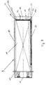
- Fig. 8, a storage magazine used in one of the devices according to Fig. 1 or 3 in supervision.
Die in den Fig. 1 und 2 gezeigte Vorrichtung 1 zum automatischen Befüllen eines Hauptmagazins 2 einer Etikettiermaschine 3 weist einen karusselförmig ausgebildeten, drehbaren Magazinträger 4 auf, auf dem im Kreis und in regelmäßigen Abständen zueinander benachbart Haltearme 5 angeordnet sind.The device 1 shown in FIGS. 1 and 2 for automatically filling a
Die in Fig. 3 gezeigt Vorrichtung unterscheidet sich von der in den Figuren 1,2 gezeigten Vorrichtung dadurch, daß bei ihr der Magazinträger 6 rechteckig ausgebildet ist und die Haltearme 5 linear nebeneinander in regelmäßigen Abständen angeordnet sind, wobei der Magazinträger 6 quer zur Längsachse 7 des Hauptmagazins 2 verfahrbar ist.The device shown in FIG. 3 differs from the device shown in FIGS. 1 and 2 in that the
Die in den Figuren 1,2,3 gezeigten Haltearme 5 weisen jeweils einen gekröpften oberen Abschnitt 5a auf, an dessen Spitze eine Schwenkeinrichtung 8 angeordnet ist. An dieser Schwenkeinrichtung 8 ist jeweils ein Vorratsmagazin 9 über ein an seiner Bodenfläche 10 angeordnetes, der Ausschuböffnung 11 des Vorratsmagazins 9 zugeordnetes Gelenkelement befestigt. Mittels dor Schwenkeinrichtung 8 ist das Vorratsmagazin 9 aus seiner vertikal ausgerichteten, hängenden Wartestellung W in eine horizontal ausgerichtete Einschubstellung E verschwenkbar. Die entsprechende Schwenkbewegung ist in den Fig. 2,2a durch Pfeile P angedeutet, wobei in Fig. 2a das Vorratsmagazin 9 in seiner hängenden Wartestellung W in gestrichelten Linien und in seiner Einschubstellung E in Vollinien dargestellt ist.The holding
Oberhalb der Haltearme 5 ist ein vom Gestell 12 der Vorrichtung 1 getragener, pneumatisch in Richtung des Hauptmagazins 2 aus einer Wartestellung ausfahrbarer Einschubstößel 13 angeordnet, dessen Längsachse fluchtend zur Längsachse 7 des Hauptmagazins 2 ausgerichtet ist. Seine Länge ist dabei in seiner Wartesteilung so bemessen, daß zwischen dem Einschubstößel 13 und dem Hauptmagazin 2 ein ausreichender Raum für das Verschwenken der Vorratsmagazine 9 in deren Einschubstellung E verbleibt.Above the holding
Jedes der Vorratsmagazine 9 ist kastenförmig ausgebildet und weist neben der Bodenfläche 10 Seitenwände 14 auf. Darüber hinaus sind auf der Bodenfläche 10 Gleitschienen 15 angeordnet, die über die Ausschuböffnung 11 und die vordere Kante der Bodenflache 10 hinausragen. Der über die vordere Kante der Bodenfläche 10 hinausragende Abschnitt der Gleitschienen 15 greift in der Einschubstellung E der Vorratsmagazine 9 in entsprechende Ausnehmungen des Hauptmagazins 2 ein.Each of the
Desweiteren weist jedes Vorratsmagazin 9 eine Rückwand 16, sowie eine gegenüber der Rückwand 16 abgefederte Platte 17 auf, über die ein in dem jeweiligen Vorratsmagazin eingefüllter Etikettenstapel 18 in der Wartestellung W der Vorratsbehälter 9 federnd abgestützt ist. Diese Anordnung der Platte 17 ermöglicht es, Etikettenstapel 18 verschiedener Länge in den Vorratsbehälter 9 einzufüllen, da aufgrund der federdernden Abstützung stets sichergestellt ist, daß die Stirnseite 18a des Etikettenstapels 18 an einer vorgegebenen Stelle der Auschuböffnung 11 des Vorratsbehälters 9 angeordnet ist.Furthermore, each
Zusätzlich ist jeder Vorratsbehälter 9 mit Halteelementen 19 ausgestattet, die sich im Inneren der Vorratsbehälter 9 jeweils beidseitig entlang eines in den Vorratsbehälter 9 eingefüllten, aus einer Vielzahl Von Einzeletiketten bestehenden Etikettenstapels 18 erstrecken. Auf die Halteelemente 19 üben Zugfedern 20 Federkräfte aus. Die Zugfedern 20 erstrecken sich jeweils längs der Halteelemente 19 und sind mit ihrem einen Ende an dem der Ausschuböffnung 11 zugeordneten Ende 19a der Halteelemente 19 und mit ihrem anderen Ende an einem rückwärtigen Abschnitt der Seitenwände 14 befestigt.In addition, each
Die Halteelemente 19 sind nach Art Von Blattfedern ausgebildet und zumindest im Bereich ihres Endes 19a in Querrichtung zu ihrer Längsachse federnd verbiegbar. An ihrem Ende 19a weisen die Halteelemente 19 jeweils zum Innern des Vorratsbehälters 9 vorstehende Vorsprünge 21 auf, die auf der Stirnseite 18a des Etikettenstapels 18 aufliegen und ein ungewolltes Austreten einzelner Etiketten des Etikettenstapels 18 aus dem Vorratsbehälter 9 verhindern. Darüber hinaus ist am Ende 19a der Halteelemente 19 ein in einer trichterförmigen Rundung nach Außen von dem Etikettenstapel 18 weggerichteter Abschnitt 22 ausgebildet.The holding
Das Hauptmagazin 2 weist eine Führungsbahn 23 für einen in das Hauptmagazin 2 eingeschobenen Etikettenstapel 24 auf. Im Bereich der Einschuböffnung 2a des Hauptmagazins 2 benachbart zu den beiden Seiten der Führungsbahn 23 ist jeweils ein als von einem Zapfen getragene Rolle 25 ausgebildetes Führungselement 26 angeordnet.The
Innerhalb des Hauptmagazins 2 wird der eingeschobene Etikettenstapel 24 durch Förderelemente 27 in Richtung von Leimsegmenten 28 der Etikettiermaschine 3 gefördert. Die Förderelemente 27 sind dazu schwenkbar an eine Fördereinrichtung 29 befestigt und werden jeweils durch eine Drehfeder 30 in Anlage an den eingeschobenen Etikettenstapel 24 gehalten.Within the
Das Hauptmagazin 2 ist darüber hinaus mit nicht gezeigten Verbrauchssensoren ausgestattet, die den Verbrauch der Etiketten des in das Hauptmagazin 2 eingeschobenen Etikettenstapels 24 überwachen. Die Verbrauchssensoren melden die Notwendigkeit eines Nachfüllens des Hauptmagazins 2 mit einem neuen Etikettenstapel 18 so frühzeitig, daß stets eine ausreichende Menge an Etiketten in dem Hauptmagazin 2 enthalten sind, um die Etikettiermaschine 3 unter Berücksichtigung des Nachfüllvorganges unterbrechungsfrei zu betreiben.The
Die vorstehend erläuterte Vorrichtung arbeitet wie folgt:
Sobald die Verbrauchssensoren des Hauptmagazins 2 melden, daß ein Nachfüllen des Hauptmagazins 2 erforderlich ist, wird einer der Vorratsbehälter 9 mittels des Magazinträgers 4 in seine Schwenkposition gefördert, in der er unmittelbar vor dem Hauptmagazin 2 der Etikettiermaschine 3 angeordnet ist. Dabei ist der jeweilige Haltearm 9 platzsparend unterhalb des Hauptmagazins 2 angeordnet.The device explained above works as follows:
As soon as the consumption sensors of the
Anschließend wird der jeweilige Vorratsbehälter 9 in seine Einschubstellung E geschwenkt (Fig. 2a), in der er horizontal fluchtend zu dem Hauptmagazin 2 ausgerichtet ist. Die Ausschuböffnung 11 des Vorratsbehälters 9 liegt nun bündig an der Einschuböffnung des Hauptmagazins 2 an, wobei durch die in das Hauptmagazin 2 vorstehenden Abschnitte der Gleitschienen 15 sichergestellt ist, daß der neue Etikettenstapel 18 stoßfrei in das Hauptmagazin 2 eingeschoben werden kann.The
Anschließend fährt der Einschubstößel 13 in das Vorratsmagazin 9 ein und schiebt den Etikettenstapel 18 in Richtung des Hauptmagazins 2 vor. Dabei werden die Halteelemente 19 über ihre Vorsprünge 21 mitgenommen und üben eine durch die Zugfedern 20 erzeugte Kraft auf den Etikettenstapel 18 aus, bis das Ende des sich schon in dem Hauptmagazin 2 befindenden, verbrauchten Etikettenstapels 24 annähernd erreicht ist. In dieser Stellung treffen die trichterförmigen Abschnitte 22 der Halteelemente 19 auf die Rolle 25 des jeweiligen Führungselements 26 (Fig. 4a,b).Then the slide-in
Das weitere Einschieben des Etikettenstapels 18 in das Hauptmagazin 2 bewirkt, daß der trichterförmige Abschnitt 22 der Halteelemente 19 durch das Führungselement 26 unter einer Verbiegung des Halteelements 19 in Querrichtung zu seiner Längsachse von dem Etikettenstapel 18 weggeführt wird. Mit diese Verbiegung geht ein Wegschwenken der Vorsprünge 21 der Halteelemente 19 von der Stirnseite 18a des Etikettenstapels 18 einher (Fig. 5a,b).The further insertion of the
Sobald die Vorsprünge 21 vollständig von der Stirnseite 18a des Etikettenstapels 18 wegbewegt sind, so daß dieser frei von der Kraftbelastung durch die Halteelemente 19 ist, schnellen die Halteelemente 19 gezogen durch die Zugfedern 20 in ihre Ausgangsposition zurück. Die Stirnseite 18a des neu eingeschobenen Etikettenstapels 18 liegt nun an den Förderelementen 27 an (Fig. 6a,6b).As soon as the
Zuletzt werden die Förderelemente 27 in einer durch die Fördereinrichtung 29 ausgelösten Schwenkbewegung zwischen den Etikettenstapeln 18,24 herausgezogen. Anschließend fährt die Fördereinrichtung 29 mit den Förderelementen 27 an das Ende des neu eingeschobenen Etikettenstapels 18, wo diese hinter den Etikettenstapel 18 schwenken. Der Etikettenstapel 18 kann nun im Hauptmagazin 2 in Richtung der Leimsegmente 28 der Etikettiermaschine 3 gefördert werden (Fig. 7a,b).Finally, the conveying
Claims (15)
Applications Claiming Priority (2)
| Application Number | Priority Date | Filing Date | Title |
|---|---|---|---|
| DE4417497A DE4417497A1 (en) | 1994-05-19 | 1994-05-19 | Device for automatically filling the main magazine of a labeling machine, as well as a storage magazine that can be used in such a device |
| DE4417497 | 1994-05-19 |
Publications (2)
| Publication Number | Publication Date |
|---|---|
| EP0683101A2 true EP0683101A2 (en) | 1995-11-22 |
| EP0683101A3 EP0683101A3 (en) | 1996-01-03 |
Family
ID=6518452
Family Applications (1)
| Application Number | Title | Priority Date | Filing Date |
|---|---|---|---|
| EP95107068A Withdrawn EP0683101A2 (en) | 1994-05-19 | 1995-05-10 | Device for automatically filling the main magazine of a labelling machine and magazine for use in such a device |
Country Status (4)
| Country | Link |
|---|---|
| US (1) | US5569353A (en) |
| EP (1) | EP0683101A2 (en) |
| BR (1) | BR9502482A (en) |
| DE (1) | DE4417497A1 (en) |
Cited By (1)
| Publication number | Priority date | Publication date | Assignee | Title |
|---|---|---|---|---|
| EP0836999A1 (en) * | 1996-10-19 | 1998-04-22 | Kronseder, Hermann, Dr.-Ing. E.h. | Label magazine device in labelling machines |
Families Citing this family (25)
| Publication number | Priority date | Publication date | Assignee | Title |
|---|---|---|---|---|
| DE19712193C5 (en) * | 1997-03-22 | 2008-06-12 | Khs Ag | Change magazine for labels of a labeling machine |
| JP3808581B2 (en) * | 1997-03-25 | 2006-08-16 | 株式会社湯山製作所 | Injection dispensing device |
| US6170700B1 (en) | 1998-11-06 | 2001-01-09 | Kalish Canada Inc. | Leaflet dispensing apparatus |
| DE10007089A1 (en) | 2000-02-16 | 2001-08-23 | Focke & Co | Device for handling blanks, in particular banderoles for cigarette packs |
| ITPR20010053A1 (en) * | 2001-08-24 | 2003-02-24 | Sig Alfa Spa | LABEL WAREHOUSE, IN PARTICULAR FOR LABELING MACHINES. |
| ATE242158T1 (en) | 2001-11-08 | 2003-06-15 | Kosme Srl | AUTOMATIC MAGAZINE FOR FEEDING LABELS TO LABELING MACHINES |
| ITBO20040670A1 (en) * | 2004-10-28 | 2005-01-28 | Gd Spa | POWER SUPPLY UNIT OF WRAPPING MATERIAL GROUPED IN BATTERIES TO A PACKAGING MACHINE |
| US7694843B2 (en) | 2005-05-27 | 2010-04-13 | Prairie Packaging, Inc. | Reinforced plastic foam cup, method of and apparatus for manufacturing same |
| US7818866B2 (en) | 2005-05-27 | 2010-10-26 | Prairie Packaging, Inc. | Method of reinforcing a plastic foam cup |
| US7814647B2 (en) | 2005-05-27 | 2010-10-19 | Prairie Packaging, Inc. | Reinforced plastic foam cup, method of and apparatus for manufacturing same |
| US7704347B2 (en) | 2005-05-27 | 2010-04-27 | Prairie Packaging, Inc. | Reinforced plastic foam cup, method of and apparatus for manufacturing same |
| US9612369B2 (en) | 2007-08-12 | 2017-04-04 | Toyota Motor Engineering & Manufacturing North America, Inc. | Red omnidirectional structural color made from metal and dielectric layers |
| US10690823B2 (en) | 2007-08-12 | 2020-06-23 | Toyota Motor Corporation | Omnidirectional structural color made from metal and dielectric layers |
| US10870740B2 (en) | 2007-08-12 | 2020-12-22 | Toyota Jidosha Kabushiki Kaisha | Non-color shifting multilayer structures and protective coatings thereon |
| US9739917B2 (en) | 2007-08-12 | 2017-08-22 | Toyota Motor Engineering & Manufacturing North America, Inc. | Red omnidirectional structural color made from metal and dielectric layers |
| US10048415B2 (en) | 2007-08-12 | 2018-08-14 | Toyota Motor Engineering & Manufacturing North America, Inc. | Non-dichroic omnidirectional structural color |
| DE102007062471A1 (en) * | 2007-12-20 | 2009-06-25 | Krones Ag | Apparatus and method for applying labels |
| US8828170B2 (en) | 2010-03-04 | 2014-09-09 | Pactiv LLC | Apparatus and method for manufacturing reinforced containers |
| DE102012101114A1 (en) * | 2012-02-14 | 2013-08-14 | Krones Ag | Device for providing consumables |
| US9664832B2 (en) | 2012-08-10 | 2017-05-30 | Toyota Motor Engineering & Manufacturing North America, Inc. | Omnidirectional high chroma red structural color with combination semiconductor absorber and dielectric absorber layers |
| US9678260B2 (en) | 2012-08-10 | 2017-06-13 | Toyota Motor Engineering & Manufacturing North America, Inc. | Omnidirectional high chroma red structural color with semiconductor absorber layer |
| US9658375B2 (en) | 2012-08-10 | 2017-05-23 | Toyota Motor Engineering & Manufacturing North America, Inc. | Omnidirectional high chroma red structural color with combination metal absorber and dielectric absorber layers |
| JP6741586B2 (en) | 2014-04-01 | 2020-08-19 | トヨタ モーター エンジニアリング アンド マニュファクチャリング ノース アメリカ,インコーポレイティド | Multi-layer structure without color shift |
| US9810824B2 (en) | 2015-01-28 | 2017-11-07 | Toyota Motor Engineering & Manufacturing North America, Inc. | Omnidirectional high chroma red structural colors |
| DE102022101940A1 (en) * | 2022-01-27 | 2023-07-27 | Espera-Werke Gmbh | Procedure for operating a labeling system |
Citations (3)
| Publication number | Priority date | Publication date | Assignee | Title |
|---|---|---|---|---|
| DE3536294A1 (en) * | 1985-10-11 | 1987-04-16 | Hermann Kronseder | Method and apparatus for exchanging the interchangeable magazines of a magazine device for labels in labelling machines |
| FR2631011A1 (en) * | 1988-05-04 | 1989-11-10 | Astinfrance Sarl | Method of transferring a pile of flat products and device for handling such a pile |
| EP0537823A1 (en) * | 1991-10-15 | 1993-04-21 | Peter Theel | A device for feeding cardboard sheets to processing machines |
Family Cites Families (9)
| Publication number | Priority date | Publication date | Assignee | Title |
|---|---|---|---|---|
| US1536835A (en) * | 1925-05-05 | Ezst t hojbjii pstti | ||
| US2060193A (en) * | 1933-07-21 | 1936-11-10 | Us Rubber Co | Label applying machine |
| US3180521A (en) * | 1963-04-08 | 1965-04-27 | Jo Dee Corp | Rotary dispenser |
| CA1003792A (en) * | 1973-01-25 | 1977-01-18 | Hermann Kronseder | Method and apparatus for tray loading of labels into label magazines |
| US4369089A (en) * | 1980-04-30 | 1983-01-18 | Jagenberg-Werke Ag | Apparatus for changing the label magazine boxes of labelling machines |
| BR8207560A (en) * | 1982-02-16 | 1983-10-25 | Jagenberg Ag | LABELING STATION FOR OBJECTS LIKE BOTTLES |
| DE3402514A1 (en) * | 1984-01-26 | 1985-08-01 | Focke & Co, 2810 Verden | DEVICE FOR PACKAGING ITEMS, IN PARTICULAR CIGARETTES |
| EP0190633A1 (en) * | 1985-02-02 | 1986-08-13 | Hermann Kronseder | Label magazine device for labeling machines and method for exchanging refill magazines |
| DE3630925C3 (en) * | 1986-09-11 | 1988-03-24 | Hermann Kronseder | MAGAZINE DEVICE FOR LABELS IN LABELING MACHINES |
-
1994
- 1994-05-19 DE DE4417497A patent/DE4417497A1/en not_active Withdrawn
-
1995
- 1995-05-10 EP EP95107068A patent/EP0683101A2/en not_active Withdrawn
- 1995-05-19 BR BR9502482A patent/BR9502482A/en not_active Application Discontinuation
- 1995-05-19 US US08/444,621 patent/US5569353A/en not_active Expired - Fee Related
Patent Citations (3)
| Publication number | Priority date | Publication date | Assignee | Title |
|---|---|---|---|---|
| DE3536294A1 (en) * | 1985-10-11 | 1987-04-16 | Hermann Kronseder | Method and apparatus for exchanging the interchangeable magazines of a magazine device for labels in labelling machines |
| FR2631011A1 (en) * | 1988-05-04 | 1989-11-10 | Astinfrance Sarl | Method of transferring a pile of flat products and device for handling such a pile |
| EP0537823A1 (en) * | 1991-10-15 | 1993-04-21 | Peter Theel | A device for feeding cardboard sheets to processing machines |
Cited By (1)
| Publication number | Priority date | Publication date | Assignee | Title |
|---|---|---|---|---|
| EP0836999A1 (en) * | 1996-10-19 | 1998-04-22 | Kronseder, Hermann, Dr.-Ing. E.h. | Label magazine device in labelling machines |
Also Published As
| Publication number | Publication date |
|---|---|
| BR9502482A (en) | 1995-12-19 |
| US5569353A (en) | 1996-10-29 |
| EP0683101A3 (en) | 1996-01-03 |
| DE4417497A1 (en) | 1995-11-23 |
Similar Documents
| Publication | Publication Date | Title |
|---|---|---|
| EP0683101A2 (en) | Device for automatically filling the main magazine of a labelling machine and magazine for use in such a device | |
| EP0222344B1 (en) | Device for testing and sorting electronic components | |
| DE3540201A1 (en) | DEVICE FOR AUTOMATICALLY MOUNTING TENSION SPRINGS | |
| EP0941654B1 (en) | Ear tag applicator tool. | |
| CH454010A (en) | Device for placing pieces of confectionery aligned on a feed device into packaging | |
| DE3221620A1 (en) | DEVICE FOR ATTACHING COMPONENTS | |
| EP0344763B1 (en) | Tape magazine for smd-manipulators | |
| DE3002250C2 (en) | Device for providing labels on a labeling machine | |
| EP0380930A1 (en) | Suspended transport system | |
| DE2655040C3 (en) | Coin dispenser | |
| DE3825273A1 (en) | Bobbin-transport device with a projecting mandrel | |
| DE3712087C2 (en) | ||
| DE3929405C2 (en) | Device for feeding textile tubes | |
| DE4344744A1 (en) | Appliance for inserting packages filled with pourable contents into containers | |
| DE4102899A1 (en) | Automatic hinge assembling machine - has slides working at right angles transporting mounting from feed conveyor | |
| EP3718711A2 (en) | Method for operating a robot, tool head for a robot and processing line with a robot | |
| DE3429285A1 (en) | DEVICE FOR COVERING BLOCKS | |
| DE19926713B4 (en) | Device for handling banderoles | |
| DE1218254B (en) | Device for feeding a pipe bending machine | |
| DE3534664A1 (en) | Label container for labelling machines | |
| DE4328359A1 (en) | Holder for plate-shaped objects, in particular circuit boards and removal and loading device for this holder | |
| DE3536294C2 (en) | ||
| DE19712193C5 (en) | Change magazine for labels of a labeling machine | |
| DE3040195A1 (en) | ALIGNMENT DEVICE FOR TAPE CASSETTES | |
| DE3409395A1 (en) | Apparatus for the automatic laying of spacing laths |
Legal Events
| Date | Code | Title | Description |
|---|---|---|---|
| PUAI | Public reference made under article 153(3) epc to a published international application that has entered the european phase |
Free format text: ORIGINAL CODE: 0009012 |
|
| PUAL | Search report despatched |
Free format text: ORIGINAL CODE: 0009013 |
|
| AK | Designated contracting states |
Kind code of ref document: A2 Designated state(s): AT CH DE FR GB IT LI |
|
| AK | Designated contracting states |
Kind code of ref document: A3 Designated state(s): AT CH DE FR GB IT LI |
|
| 17P | Request for examination filed |
Effective date: 19960129 |
|
| GRAG | Despatch of communication of intention to grant |
Free format text: ORIGINAL CODE: EPIDOS AGRA |
|
| GRAG | Despatch of communication of intention to grant |
Free format text: ORIGINAL CODE: EPIDOS AGRA |
|
| GRAG | Despatch of communication of intention to grant |
Free format text: ORIGINAL CODE: EPIDOS AGRA |
|
| 17Q | First examination report despatched |
Effective date: 19960923 |
|
| GRAH | Despatch of communication of intention to grant a patent |
Free format text: ORIGINAL CODE: EPIDOS IGRA |
|
| RAP3 | Party data changed (applicant data changed or rights of an application transferred) |
Owner name: KHS ETI-TEC MASCHINENBAU GMBH |
|
| STAA | Information on the status of an ep patent application or granted ep patent |
Free format text: STATUS: THE APPLICATION IS DEEMED TO BE WITHDRAWN |
|
| 18D | Application deemed to be withdrawn |
Effective date: 19970301 |