EP0683050B1 - Tintenversorgungsvorrichtung und zugehöriges Tintenstrahlaufzeichnungsgerät - Google Patents
Tintenversorgungsvorrichtung und zugehöriges Tintenstrahlaufzeichnungsgerät Download PDFInfo
- Publication number
- EP0683050B1 EP0683050B1 EP95107689A EP95107689A EP0683050B1 EP 0683050 B1 EP0683050 B1 EP 0683050B1 EP 95107689 A EP95107689 A EP 95107689A EP 95107689 A EP95107689 A EP 95107689A EP 0683050 B1 EP0683050 B1 EP 0683050B1
- Authority
- EP
- European Patent Office
- Prior art keywords
- ink
- filter
- flow passage
- chamber
- disposed
- Prior art date
- Legal status (The legal status is an assumption and is not a legal conclusion. Google has not performed a legal analysis and makes no representation as to the accuracy of the status listed.)
- Expired - Lifetime
Links
- 230000005484 gravity Effects 0.000 claims description 28
- 230000001154 acute effect Effects 0.000 claims 1
- 238000001914 filtration Methods 0.000 description 18
- 239000007788 liquid Substances 0.000 description 11
- 238000012986 modification Methods 0.000 description 9
- 230000004048 modification Effects 0.000 description 9
- 238000011144 upstream manufacturing Methods 0.000 description 5
- 230000007423 decrease Effects 0.000 description 4
- 230000000694 effects Effects 0.000 description 3
- 239000000463 material Substances 0.000 description 3
- 230000004044 response Effects 0.000 description 3
- 230000008901 benefit Effects 0.000 description 2
- 230000008859 change Effects 0.000 description 2
- 238000013461 design Methods 0.000 description 2
- 238000011161 development Methods 0.000 description 2
- 239000013013 elastic material Substances 0.000 description 2
- 230000007246 mechanism Effects 0.000 description 2
- 230000003134 recirculating effect Effects 0.000 description 2
- 238000004891 communication Methods 0.000 description 1
- 230000001276 controlling effect Effects 0.000 description 1
- 238000007796 conventional method Methods 0.000 description 1
- 230000003247 decreasing effect Effects 0.000 description 1
- 230000006866 deterioration Effects 0.000 description 1
- 230000002542 deteriorative effect Effects 0.000 description 1
- 238000001704 evaporation Methods 0.000 description 1
- 230000008020 evaporation Effects 0.000 description 1
- 238000003384 imaging method Methods 0.000 description 1
- 238000009434 installation Methods 0.000 description 1
- 230000005499 meniscus Effects 0.000 description 1
- 230000002035 prolonged effect Effects 0.000 description 1
- 238000011084 recovery Methods 0.000 description 1
- 230000009467 reduction Effects 0.000 description 1
- 230000001105 regulatory effect Effects 0.000 description 1
- 239000011347 resin Substances 0.000 description 1
- 229920005989 resin Polymers 0.000 description 1
- 238000012216 screening Methods 0.000 description 1
- 238000005549 size reduction Methods 0.000 description 1
- 239000004094 surface-active agent Substances 0.000 description 1
- 238000003466 welding Methods 0.000 description 1
Images

Classifications
-
- B—PERFORMING OPERATIONS; TRANSPORTING
- B41—PRINTING; LINING MACHINES; TYPEWRITERS; STAMPS
- B41J—TYPEWRITERS; SELECTIVE PRINTING MECHANISMS, i.e. MECHANISMS PRINTING OTHERWISE THAN FROM A FORME; CORRECTION OF TYPOGRAPHICAL ERRORS
- B41J2/00—Typewriters or selective printing mechanisms characterised by the printing or marking process for which they are designed
- B41J2/005—Typewriters or selective printing mechanisms characterised by the printing or marking process for which they are designed characterised by bringing liquid or particles selectively into contact with a printing material
- B41J2/01—Ink jet
- B41J2/17—Ink jet characterised by ink handling
- B41J2/175—Ink supply systems ; Circuit parts therefor
- B41J2/17503—Ink cartridges
- B41J2/1752—Mounting within the printer
- B41J2/17523—Ink connection
-
- B—PERFORMING OPERATIONS; TRANSPORTING
- B41—PRINTING; LINING MACHINES; TYPEWRITERS; STAMPS
- B41J—TYPEWRITERS; SELECTIVE PRINTING MECHANISMS, i.e. MECHANISMS PRINTING OTHERWISE THAN FROM A FORME; CORRECTION OF TYPOGRAPHICAL ERRORS
- B41J2/00—Typewriters or selective printing mechanisms characterised by the printing or marking process for which they are designed
- B41J2/005—Typewriters or selective printing mechanisms characterised by the printing or marking process for which they are designed characterised by bringing liquid or particles selectively into contact with a printing material
- B41J2/01—Ink jet
- B41J2/17—Ink jet characterised by ink handling
- B41J2/175—Ink supply systems ; Circuit parts therefor
- B41J2/17563—Ink filters
Definitions
- the present invention relates to an ink jet recording apparatus, in particular, an ink jet recording apparatus comprising an foreign matters removing apparatus for removing foreign matters.
- the ink jet recording apparatus is liable to suffer from this blockage caused by the foreign matters or ink deposit. This is because it has ejection orifices for ejecting ink droplets, and these orifices are extremely small relative to the internal diameter of the liquid passage, being thereby liable to be blocked.
- an foreign matters removing apparatus has been disposed in an ink supplying system for supplying the ink from the ink container, which is the ink storing portion, to the ejection orifices.
- This foreign matters removing apparatus is constituted of a chamber or the like provided with a filter which removes the microscopic foreign matters or bubbles, see for example EP-A2-0 585 901.
- FIG 1 A schematic view of the basic structure of such an ink jet recording apparatus is given in Figure 1, and a schematic section of the general structure of the filter chamber as a conventional foreign matters removing apparatus, which has been employed in this ink jet recording apparatus, is given in Figure 2.
- the ink jet recording apparatus depicted in Figure 1 is of a type that carries out a performance restoring operation by recirculating the ink.
- a reference numeral 8 designates an ink container as an ink storing portion; 9, a gear pump for pressure-feeding the ink; 10, a power source for driving the gear pump; 11, a switch for controlling the driving of the pump; and a reference numeral 12 designates a recording head for ejecting the ink.
- the ink container 8 is schematically drawn with its top open, but the ink container 8 generally comprises an opening, through which the internal space thereof is in communication with the atmosphere.
- a reference numeral 20 designates a filter chamber as the foreign matters removing apparatus; 21, an inflow tube as an ink supply tube, through which the ink is flowed into the foreign matters removing apparatus; and a reference numeral 22 designates an outflow tube as an ink flow passage, through which the ink is led out of the filtering apparatus.
- This foreign matters removing apparatus 20 is disposed in both the ink passage leading from the ink container 8 to the recording head 12, and the ink flow passage returning to the ink container 8 from the recording head.
- the foreign matters removing apparatus 2 comprises a filter 1, wherein a reference numeral 2 designates an ink entrance opening and a reference numeral 3 designates an ink exit opening.
- the ink 13 from the ink container 8 enters the gear pump 9 by way of the ink supply tube 23, flows through the inflow tube 21, enters the foreign matters removing apparatus 20 disposed on the pump side through the ink entrance opening 2, passes through the filter 1, and reaches the recording head 12 by way of the ink exit opening 3.
- the ink is pressure-fed by the pump from the ink container to the recording head through the ink supply passage 23 constituting the outward passage, and the inflow tube 21,; and then, is further pressure-fed by the pump, being thereby returned from the recording head to the ink container through the outflow tube 22 constituting the return passage.
- the bubbles existing in the outward ink passage, return ink passage, and recording head are returned to the ink container, where they are separated from the ink and released into the atmosphere.
- the filter of the foreign matters removing apparatus disposed in the aforementioned outward ink passage or return ink passage must allow the bubbles to pass when the gear pump 9 is activated.
- the ink when the ink is supplied from the ink container to the recording head through the outward ink passage during a recording operation, the ink is generally not pressure-fed by the pump, and instead, is supplied using the capillary force or the like of the ink in the recording head or the like.
- the ink is supplied by the capillary force mainly from the ink exit tube 22 side, where flow resistance is smaller.
- the bubble must not be allowed to pass through the filter of the foreign matters removing apparatus. This is because when the bubbles having entered the recording head exist in the ink passage on the ejection orifice side, ejection becomes instable, and in the worst case, the ejection may become impossible.
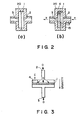
- the ink 13 flowed in from the direction of an arrow mark a is sent to the foreign matters removing apparatus 20 comprising the filter 1 through an unillustrated inflow tube.
- the ink 13, which flows through the ink exit opening 3, is filtered by the filter 1 that does not pass the foreign matters or the like larger than 10 ⁇ m in diameter. Because of the presence of this filter 1, the foreign matters 7 within the ink 13 accumulate on the arrow mark a side, which is the upstream side of the filter 1. In this case, the foreign matters do not flow into the side of an arrow mark b, which constitutes the outflow tube.
- the aforementioned bubbles are liable to enter the ink flow passage (ink supply system passage), being thereby mixed into the ink, or remain on the upstream side of the filter chamber 20. Further, it is liable that even after the bubbles having accumulated on the upstream side of the filter chamber 20 pass the filtering portion, they rise due to their buoyancy and tend to linger at the point of ink flow stagnation, which develops at the top portion of the filter 1, on the downstream side, adhering subsequently to the filter within the filter chamber and reducing thereby the effective area of the filter. As a result, it is liable that the ink pressure is reduced to a point where unsatisfactory ink ejection occurs during the recording operation.
- the recording means and ink storing portion are in the form of cartridge, and can be individually mounted in, or removed from, the recording apparatus, even though they remain integrated while they are in the recording apparatus.
- This arrangement has such an advantage that when the ink stops coming out of the recording means, the recording operation can be restarted just by replacing the ink storing portion. In other words, it reduces the running cost.
- this arrangement has a smaller component count compared to a structure in which the recording means and ink storing portion are not separable; therefore, it is easier to deal with the used components like the ink depleted ink storing portion, reducing thereby the impact on the environment.
- the dimension of the filter in the filtering portion may be increased so that the effective area through which the ink passes can be increased.
- a filter chamber is generally disposed at a predetermined point of the ink supply passage which connects the ink ejecting portion of the recording means and the ink storing portion.
- ink cartridge cartridge type ink storing portion
- recording head cartridge cartridge type recording means
- This phenomenon is similar to the one that is frequently experienced when the recording means and ink storing portion are connected with a tube or the like as described before.
- the removal of the bubbles adhering to the filter occurs when the ink is sucked through the ejection orifices of the recording means to restore the recording performance of the apparatus, and in order to remove completely the bubbles, a sucking apparatus with a large capacity is necessary, which goes against the trend of reducing the apparatus size.
- the primary object of the present invention is to solve the aforementioned various problems, and thereby, to provide an ink jet recording apparatus capable of removing effectively the bubbles so that the ink is consistently and stably ejected, wherein the ink entrance opening of the foreign matters removing apparatus is disposed at a substantially central portion thereof, and the ink exit opening is disposed at the topmost portion thereof to smooth the ink flow, eliminating thereby the development of the spot where the bubbles tend to linger, so that the bubbles can be effectively removed.
- Another object of the present invention is to provide an ink jet apparatus and an ink supplying apparatus which do not invite the increase in size and complexity thereof caused by the increase in the size or the like of the recording head cartridge provided with the ink flow passage.
- Another object of the present invention is to prevent the deterioration of the recording image quality resulting from the instable ejection caused by the bubble adhesion to the filtering portion.
- a further object of the present invention is to provide an ink jet apparatus and an ink supplying apparatus which are capable of surely removing the bubbles even when an attempt is made to reduce the apparatus size in the width direction thereof by disposing the ink storing portion and ink ejecting means on the top and bottom sides of the filter, respectively, relative to the gravity direction.
- an ink supplying apparatus comprising: an ink flow passage connecting an ink storing portion for storing ink and an ejecting portion for ejecting the ink; a chamber disposed in the ink flow passage; a filter which divides the chamber into two spaces, one of which is provided with an ink entrance opening leading to the ink storing portion, and the other of which is provided with an ink exit opening leading to the ejecting portion; wherein the ink exit opening is disposed adjacent to the top wall of the chamber, with respect to gravity direction, and also, the ink exit opening is disposed above a level at which the ink entrance opening is disposed, with respect to direction.
- an ink jet recording apparatus as defined in claim 9.
- Figure 1 is a schematic perspective view of an example of conventional foreign matters removing apparatus.
- Figure 2 is a schematic sectional view of an example of the filtering portion of the conventional foreign matters removing apparatus.
- Figure 3 is a schematic sectional view depicting the shape of the filtering portion of the ink supplying system in the conventional small ink jet apparatus.
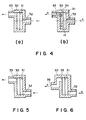
- Figure 4 is a schematic sectional view of the first embodiment of the foreign matters removing apparatus according to the present invention.
- Figure 5 is a schematic sectional view of a modification of the first embodiment of the foreign matters removing apparatus according to the present invention.
- Figure 6 is a schematic sectional view of another modification of the first embodiment of the foreign matters removing apparatus according to the present invention.
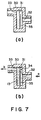
- Figure 7 is a schematic sectional view of the second embodiment of the foreign matters removing apparatus according to the present invention.
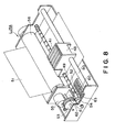
- Figure 8 is a schematic perspective view of an embodiment of ink jet apparatus according to the present invention.
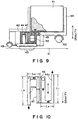
- Figure 9 is a schematic sectional view of the third embodiment of the present invention, depicting the adjacencies of the carriage portion of the ink jet apparatus.
- Figure 10 is an enlarged sectional view of the ink flow passage illustrated in Figure 9.
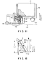
- Figure 11 is a schematic sectional view of the fourth embodiment of the present invention, depicting the adjacencies of the carriage portion of the ink jet apparatus.
- Figure 12 is an enlarged sectional view of the ink flow passage illustrated in Figure 11.
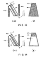
- Figures 13(a) and 13(b) are schematic sectional views of a modification of the fourth embodiment.
- Figures 14(a) and 14(b) are schematic sectional views of another modification of the fourth embodiment.
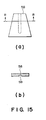
- Figures 15(a) and 15(b) are sectional views of a modification of the embodiment illustrated in Figure 14.
- Figure 4 is a schematic sectional view of the first embodiment of the present invention, depicting a filter chamber 30 as the foreign matters removing apparatus.
- the foreign matters removing apparatus of this embodiment is disposed at the same location as the foreign matters removing apparatus 20 is disposed in the ink jet recording apparatus illustrated in Figure 1.
- a reference numeral 31 designates a filter which does not allow the foreign matters such as small foreign matter or the deposit from the ink to pass. It is consisted of mesh filter of SUS or the like, and is firmly fixed within the foreign matters removing apparatus, using thermal welding or the like.
- a reference numeral 32 designates an ink entrance opening.
- this ink entrance opening is connected to the pump 9 with an inflow tube 21 or the like.
- the apparatus is disposed on the ink container 8 side, it is connected to the ink liquid chamber of the recording head 12 with the inflow tube 21 or the like.
- a reference numeral 33 designates an ink exit opening, which is disposed at the top portion of the foreign matters removing apparatus 30.
- this ink exit opening 33 is connected to the ink liquid chamber of the recording head 12 with the outflow tube 22 or the like.
- this ink exit opening 33 is connected to the ink container 8 with the outflow tube 22 or the like.
- the ink exit opening 33 is disposed at the top portion of the filter mounting portion, relative to the gravity direction, and the ink entrance opening 32 is disposed below the ink exit opening 33 in the gravity direction, as shown in Figure 4.
- the bubbles in the ink and/or the bubble 34 within the foreign matters removing apparatus 30 collect at the top portion due to the buoyancy thereof, and then, all of them are moved to the recording head 12 side through the ink exit opening 33 disposed at the topmost portion of the filter 31, by the ink flow which is generated as the means for pressure-feeding the ink, such as the gear pump 9, is driven.
- the bubble 34 enters through the ink entrance opening 32, passes through the filter 31, and is delivered to the ink container 8 through the ink exit opening 33, just as it is on the pump 9 side.
- the phenomenon that the effective area of the filter is reduced by the bubbles, which linger within the ink flow passage even after the completion of the performance restoring operation, can be prevented by changing the positional relationship between the two openings of the filter chamber from that of the conventional structure. This is because such a change causes the ink flow to change its direction within the filter chamber, which, in conjunction with the ink viscosity, suppresses the development of the point of ink stagnation where the bubbles linger.
- Figure 5 shows a modification of the preceding embodiment.
- the ink entrance opening 32 of the filter chamber is differently disposed from the preceding embodiment.
- the same components as those illustrated in Figure 4 are given the same designations to omit their descriptions.
- the ink entrance opening 32 is disposed below the center of the filter 31. This arrangement creates a stronger upward ink flow within the foreign matters removing apparatus 30 during the performance restoring operation. In other words, the ink flow component moving in the gravity direction in the filter chamber 30 increases; therefore, it becomes more difficult for the bubbles to linger in the top portion of the filter chamber 30, which in turn makes it possible to remove surely the bubbles.
- a tube connecting opening 36 that is, the external opening through which the ink flows out of the filter chamber, may be disposed so that it indirectly corresponds to the ink entrance opening 33 as shown in Figure 6.
- FIG. 7 is a schematic sectional view of the second embodiment of filter chamber as the foreign matters removing apparatus according to the present invention.
- the same components as those illustrated in Figure 4 are give the same designations to omit the descriptions.
- a valve 35 is such a valve that comes in contact with the filter 31 as shown in Figure 7(b) when the amount of the ink flow per unit of time at the filtering portion increases while the ink is circulated by the pump 9.
- the provision thereof can increase the pressure difference between the front and back sides of the filter 31 while the ink is circulated for the recovery operation; therefore, the ink flow with a higher pressure can be generated at the filter 31 by the gear pump or the like, whereby the bubbles are more efficiently passed through the filter 31.
- the ink entrance opening 32 it is more preferable for the ink entrance opening 32 to be disposed at substantially the middle portion of the foreign matters removing apparatus than at the bottom portion thereof. This is because such disposition of the ink entrance opening 32 allows the valve to move smoothly in response to the amount of the ink flow within the ink supply passage, and also, allows the valve to cling surely to the filter 31 by the entire surface thereof, so that the bubble 34 adhering to the filter surface can be easily removed.
- the disposition of the ink exit opening 33 at the top portion of the foreign matters removing apparatus 31 makes it possible to send the bubble 34 completely out of the filter chamber without inviting it to linger therein.
- the ink entrance opening of the foreign matters removing apparatus is disposed at a substantially middle portion of the foreign matters removing apparatus, or below the middle thereof, and also, when the ink exit opening is disposed at the top portion of the filter of the foreign matters removing apparatus, it is possible to remove satisfactorily the foreign matters within the ink.
- the bubbles within the ink or the bubbles accumulated within the foreign matters removing apparatus can be completely removed.
- FIG 8 a schematic perspective view of an exemplary ink jet apparatus IJRA comprising the recording means and ink storing portion, which are mounted on the carriage, is given in Figure 8.
- a reference numeral 41 designates an ink cartridge as the ink storing portion
- a reference numeral 48 designates a carriage on which the ink cartridge 41 and a recording head cartridge 42 as the recording means, which will be described later, are removably mounted.
- a reference numeral 49 designates a lead screw for making the carriage 48 scan a recording medium 51 such as a sheet of recording paper or plastic material
- a reference numeral 50 designates a guide rail for guiding the scanning movement of the carriage 48.
- the movement of the lead screw 49 is linked to the forward and backward rotation of a driving motor 55 by way of gears 53 and 54, wherein a spiral groove 52 cut in the lead screw 49 is in engagement with an unillustrated engagement portion provided on the carriage 48, and therefore, the carriage 48 is driven to scan in the longitudinal direction of the apparatus by the driving motor 55.
- the recording medium 51 is conveyed by a platen roller 56.
- performance restoring means for restoring the performance of the ejecting portion provided in the recording means, which will be described later, is disposed adjacent to the path of the recording medium 51.
- This performance restoring means comprises a cap member 60 for capping the ejection orifice portion (unillustrated) of the recording head cartridge, and a sucking means 61 for restoring the performance of the ejecting portion by sucking it through an internal opening (unillustrated) provided within the cap member 60.
- the driving force from the driving motor 55 is transmitted by well-known transmitting means comprising a gear 62, a switching clutch, and the like.
- the cap member 60 As for the vertical and related movements of the cap member 60, it is caused by the driving force transmitted by way of a gear 63 or the like, wherein, in order to suck the ejection orifices to restore their performance, and in order to slow the ink evaporation, the cap member 60 is placed airtightly in contact with the surface where the ejection orifices are present.
- the aforementioned performance restoring sucking operation can not only restore the performance of the clogged ejection orifices, but also discharge the ink contained in the ink flow passage portion between the ink cartridge and ejecting portion by changing the amount of the ink to be sucked, so that the microscopic foreign matters, bubbles, or the like can be removed from the filtering portion as well as the ink flow passage.
- This ink flow passage performance restoring operation is carried out with regular intervals, or is compulsively carried out whenever determined to be necessary by a user, so that preferable print quality can be maintained.
- the aforementioned capping and performance restoring sucking operation are carried out at the correspondent locations while the carriage 48 is in the appropriate region on the home position side. Also, these operations are performed, independently or in combination, using well-known timing and sequence, or optionally.
- FIG. 9 Given in Figure 9 is a schematic sectional view of the third embodiment of the present invention, depicting a recording head cartridge and an ink cartridge, which are on the carriage of an ink jet recording apparatus.
- Figure 10 Given in Figure 10 is an enlarged sectional view of an ink flow passage 44 constituting the ink supplying system (ink supplying apparatus) illustrated in Figure 9.
- the arrow mark A in the drawing indicates the gravity direction.
- a reference numeral 41 designates an ink cartridge, which is an ink storing portion for storing the ink
- a reference numeral 42 designates a recording head cartridge as the recording means for recording images using the ink supplied from the ink cartridge 41.
- a reference numeral 43 designates the ejecting portion comprising nuzzles (ejection orifices) for ejecting the ink
- a reference numeral 44 designates an ink flow passage connecting the ink cartridge 41 and ejecting portion 43.
- a reference numeral 45 designates a joint portion which watertightly connects the interior of the ink cartridge to the ink flow passage 44 when the ink cartridge 41 is mounted, and which seals the ink cartridge 41 when the ink cartridge 41 is removed.
- this joint portion 45 is formed of elastic material, like rubber, wherein the tip of the ink flow passage 44 is connected to this joint portion 45 of elastic material using a well-known conventional method.
- the ink flow passage 44 comprises a double-back flow passage portion 47 containing a filter 46, and the other ink flow passage portions connecting this double-back flow passage portion 47 to the ink storing portion and ejecting portion, respectively.
- this double-back flow passage constitutes the filter chamber.
- the pressure at the nozzle portion of the ink cartridge 41 is set below the atmospheric pressure with the provision of a well-known pressure regulating mechanism such as a multi-chamber structure comprising a connecting portion for forming a meniscus.
- the aforementioned ink cartridge 41 and recording head cartridge 42 are structured so that they can be removably mounted on the carriage 48.
- This carriage 48 is supported by a guide shaft 49, which is a rail provided in the ink jet apparatus, and is moved on the guide shaft for scanning during the recording operation.
- the recording medium 50 is placed perpendicular to the gravity direction, whereas the ink ejected from the nozzle 43 flies in parallel to the gravity direction.
- an ink flow passage 44a is a connecting passage leading to the ink cartridge 41 storing the ink
- the bottom end of an ink flow passage 44b is a connecting passage leading to the recording head cartridge 42 comprising the ejecting portion.
- the sectional configuration of the ink flow passage it is bent; more specifically, it doubles back at the top and bottom portions of the filter chamber 47.
- the ink flow passage 44 is structured to have a bent portion at a point where the ink flow passage 44a connects to the double-back flow passage 47, and at a point where the double-back flow passage 47 connects to the ink flow passage 44b; in other words, the double-back flow passage is disposed between the two bent portions.
- the ink flows down from the ink cartridge 41 side through the ink flow passage 44a in the gravity direction; flows into the adjacencies of the bottom portion of the double-back flow passage 47 in which the filter 46 is disposed; and thereafter, flows through the double-back flow passage 47 in the direction opposite to the gravity direction, that is, in the direction of the buoyancy indicated by an arrow mark B in the drawing. Then, the ink enters the ink flow passage 44b from the adjacencies of the topmost portion of the double-back flow passage 47; flows downward again in the gravity direction; and reaches the ejecting portion 43 side where the nozzles are.
- This ink flow described above results from the pressure difference between the pressure generated at the ejecting portion by the sucking means 61 and the cap 60 adhering airtightly to the ejecting portion, and the pressure working on the ink cartridge.
- the ink flow passages 44a and 44b are made relatively small, and given a uniform cross section across their length, so that this bubble movement can be enhanced. Therefore, the speed of the ink flow increases within the ink flow passages 44a and 44b, detaching easily the bubbles adhering to the flow passage walls, and thereby, making it easier for them to be discharged from the ejecting portion during the performance restoring operation.
- the filter chamber 47 As for the filter chamber 47 constituted of the double-back flow passage, it extends in the gravity direction, being connected to the ink flow passages 44a and 44b at the bottom and top portions, respectively.
- the opening portions are disposed at the bottommost and topmost portions, respectively.
- the filter chamber is structured so as to allow the ink to flow in the direction of the buoyancy working on the bubbles; therefore, not only the bubbles clinging to the filter 46 are more easily detached, but also, the bubbles within the ink flow passage 44a can also be more easily passed through the filter 46, during the performance restoring operation. Consequently, the bubble removal from the filtering portion by the performance restoring sucking operation can be rendered more reliable.
- the filter is disposed in parallel to the direction of the ink flow within the filter chamber 47 constituted of the double-back flow passage; therefore, the effective area of the filter can be increased without increasing the cross section of the double-back flow passage, relative to the direction of the ink flow.
- the filter is disposed in parallel to the direction of the ink flow within the filter chamber 47 constituted of the double-back flow passage; therefore, the effective area of the filter can be increased without increasing the cross section of the double-back flow passage, relative to the direction of the ink flow.
- Figure 11 is a schematic sectional view of a recording head cartridge and an ink cartridge, which are on the carriage of an ink jet recording apparatus.
- Figure 12 is an enlarged sectional view of the ink flow passage 44 illustrated in Figure 11.
- the structure of this embodiment is different from the aforementioned embodiment in that the filter chamber 47b is tilted relative to the gravity direction (or the horizontal direction perpendicular to the gravity direction).
- the ink flow passage 44a and 44b are relatively narrow, having a uniform cross section across their length; therefore, the speed of the ink flow is increased within the ink flow passages 44a and 44b. They are connected to the bottommost and topmost portions, respectively, of the filter chamber 47b constituted of the double-back flow passage.
- the reduction of the total wall surface area decreases the probability of the gas permeation into the ink flow passage, which is frequently observed during a prolonged usage.
- the foreign matters removing apparatus is structured like this embodiment in which the filter 46 is disposed so as to extend in the direction of the slanted flow passage 47b, it is possible to make it more difficult for the microscopic bubbles to cling to the filter 46, and also, it becomes easier to remove them from the flow passage.
- the microscopic bubbles mentioned above it is more liable for them to develop when surfactant is mixed into the ink as means for obtaining picture quality of a higher degree. Since the cross sections of these microscopic bubbles are extremely small, the ink pressure does not satisfactorily affect them; in other words, it is rather difficult to force them through the filtering portion.
- the bubbles with an approximately the same size as the mesh size of the filter adhere to the filter, they tend to remain there in stable condition due to the surface tension or the like; therefore, it is difficult to remove them, reducing consequently the effective area of the filter.
- the double-back ink flow passage 47b and filter 46 are disposed with a certain angle relative to the gravity direction or the horizontal direction perpendicular to the gravity direction; therefore, the buoyancy of the bubbles effects in the direction of detaching them from the filter.
- Figure 13(a) is a schematic sectional view of the ink flow passage 44
- Figure 13(b) is a schematic sectional view of the ink flow passage 44, at a sectional line P - P indicated in Figure 13(a).
- a trapezoidal configuration illustrated in Figure 13(b) is employed for the double-back flow passage so that the cross section of the filter chamber constituting a portion of the ink flow passage 44 gradually decreases toward the top.
- the speed of the ink flow drops once as the ink enters from the ink flow passage 44a into the filter chamber, and thereafter, gradually increases toward the top of the filter chamber 47b, becoming fastest at the topmost portion of the filter chamber 47b, where the bubbles are most likely to collect.
- This effect in conjunction with the aforementioned effects of the preceding embodiment, further reduces the force necessary to pass the bubbles through the filter 46; therefore, the force necessary to be applied to the filtering portion, that is, the force required of the sucking means, decreases.
- this embodiment allows the apparatus size to be further reduced, and also allows the mesh size to be further reduced, so that the nozzle size can be further reduced to improve the image resolution.
- the trapezoidal configuration is employed in this embodiment, the configuration is not limited to this one, and may be optionally selected as long as it reduces the cross section of the double-back flow passage portion toward the top.
- Figure 14 illustrates another modification for increasing the ink flow speed adjacent to the top portion of the double-back ink flow passage 47b, where the double-back ink flow passage 47b is connected to the top end opening of the ink flow passage 44b.
- a valve mechanism is added to the structure described in the foregoing in order to increase further the ink flow speed during the performance restoring operation.
- Figure 14(a) is a schematic sectional view of the ink flow passage 44
- Figure 14(b) is a schematic sectional view of the ink flow passage 44, at a sectional line Q - Q indicated in Figure 14(a).
- this structure comprises a valve 57 which remains separated from the filter 64 during an actual recording operation, that is, while the performance restoring operation is not carried out.
- the valve 57 is placed in the filter chamber, on the ink flow passage 44a side of the filter 46, that is, on the ink storing portion side. It is a 10 - 100 ⁇ m thick sheet of resin material such as PPS.
- valve 57 As for the configuration and material for the valve 57, they are not limited to those described in the foregoing as long as they can provide such elasticity that does not allow the valve 57 to come in contact with the filtering portion when the ink is slowly flowing, as it is during the actual recording operation, and allows it adhere to the filter so that the effective area of the filter is reduced when the pressure difference between the upstream and downstream sides of the filter is large, as it is during the performance restoring operation.
- the valve is structured as described below.
- Figure 15 shows such a valve structure.
- Figure 15(a) is a schematic view of such a valve as seen from the direction of Q indicated in Figure 14, and
- Figure 15(b) is a schematic sectional view of the same valve, at a sectional line R - R indicated in Figure 15(a).
- a grooved portion 59 is provided on the valve 58. This structure is particularly effective when the bubbles are lodging between the filter and valve due to the surface tension or the like. The presence of the grooved portion 59 enhances the upward movement of the bubbles in the filter chamber, in conjunction with the buoyancy of the bubbles themselves, and the surface tension which works to sphere the bubbles; therefore, the bubbles can be discharged from between the filter and valve.
- the present invention can be employed in a device having only a small space available for the placement of the filter chamber, such as the aforementioned carriage on which the recording means and ink storing portion are mounted, wherein since the structure employed is such that the ink is allowed to flow in the direction in which the buoyancy of the bubbles works, not only the detachment of the bubbles adhering to the filter becomes easier, but also, it becomes easier for the bubbles within the ink flow passage to pass through the filter. Therefore, the bubble removal by the performance restoring operation can be rendered more reliable.
- a double-back flow passage portion constituting a portion of an ink flow passage portion is disposed between two bends of the ink flow passage in a manner to intersect with the gravity direction, and a filter is disposed in a manner to extend in the same direction as this ink flow passage portion between these two bends extends, that is, in a manner to extend in the direction of the ink flow; therefore, the effective area of the filter can be increased without increasing the cross section of the in flow passage, relative to the ink flow direction, as it is increased when a conventional filtering portion is employed.
- the pressure loss which occurs when the ink passes through the filter during the recording operation can be reduced, affording an increased amount of the ink supplied per unit of time for high speed printing, and also, ink supply capacity does not deteriorate even when the mesh size of the filter is reduced to increase the print resolution.
- the loss of the force which works on the bubbles during the performance restoring operation can be reduced.
Landscapes
- Ink Jet (AREA)
Claims (11)
- Tintenversorgungsvorrichtung, welche folgende Elemente aufweist:wobei bezüglich der Schwerkraftrichtung die Tintenaustrittsöffnung an der oberen Wand der Kammer und oberhalb der Tinteneintrittsöffnung angeordnet ist.einen Tintenströmungskanal, welcher den Tintenspeicher und den Tintenausstoßabschnitt miteinander verbindet,eine Tintenkammer, welche in diesem Tintenströmungskanal angeordnet ist,einen Filter, welcher diese Kammer in zwei Räume unterteilt, in einen Raum mit einer zum Tintenspeicher führenden Tinteneintrittsöffnung undeinen Raum mit einer zum Ausstoßabschnitt führenden Tintenaustrittsöffnung,
- Tintenversorgungsvorrichtung gemäß Anspruch 1, wobei die Kammer ein Blättchenelement aufweist, welches zwischen dem Filter und der Tinteneintrittsöffnung neben dem Filter angeordnet ist, der Tinteneintrittsöffnung gegenüberliegt und einen Teil des Filters bedeckt, wenn die pro Zeiteinheit strömende Tintenmenge größer ist als die zum Aufzeichnen benötigte.
- Tintenversorgungsvorrichtung gemäß Anspruch 1, wobei der Tintenspeicher oberhalb des Ausstoßabschnitts angeordnet ist, die Kammer sich in der Richtung erstreckt, welche die Richtung senkrecht zur Schwerkraftrichtung schneidet, und der Filter parallel zur Anordnungsrichtung der Kammer angeordnet ist.
- Tintenversorgungsvorrichtung gemäß Anspruch 3, wobei die Richtung, in welcher die Kammer angeordnet ist, ebenfalls die Schwerkraftrichtung schneidet.
- Tintenversorgungsvorrichtung gemäß Anspruch 3, wobei der Tintenströmungskanal einen ersten, die Kammer und den Tintenspeicher miteinander verbindenden Tintenströmungskanalabschnitt und einen zweiten, die Kammer und den Ausstoßabschnitt miteinander verbindenden Tintenströmungskanalabschnitt aufweist und der erste und der zweite Tintenströmungskanalabschnitt von der Kammer aus unter einem spitzen Winkel verlaufen.
- Tintenversorgungsvorrichtung gemäß Anspruch 3, wobei bezüglich der Schwerkraftrichtung der Querschnitt der Kammer im unteren Abschnitt größer ist als im Abschnitt neben der Tintenaustrittsöffnung und dieser Querschnitt parallel zu der Ebene verläuft, welche sich senkrecht zur Tintenströmungsrichtung erstreckt.
- Tintenversorgungsvorrichtung gemäß Anspruch 5, wobei ein Ventil zwischen dem Kammerfilter und der Öffnung des ersten Strömungskanalabschnitts angeordnet ist und die Gesamtfläche dieses Ventils kleiner ist als die gesamte Filterfläche.
- Tintenversorgungsvorrichtung gemäß Anspruch 5, wobei auf der zum Filter gerichteten Seite des Ventils eine Nut vorhanden ist.
- Tintenstrahlaufzeichnungsgerät, welches außer dem Tintenströmungskanal, der den Tintenspeicher und den Tintenausstoßabschnitt miteinander verbindet, noch eine Kammer aufweist, die an einer bestimmten Stelle des Tintenströmungskanals angeordnet und mit einem Filter ausgerüstet ist, wobei dieser Filter die Kammer in zwei Räume teilt, in einen Raum mit einer zum Tintenspeicher führenden Tinteneintrittsöffnung und einen Raum mit einer zum Ausstoßabschnitt führenden Tintenaustrittsöffnung, und wobei die Tintenaustrittsöffnung bezüglich der Schwerkraftrichtung neben der oberen Kammerwand und an einer höheren Stelle als die Tinteneintrittsöffnung angeordnet ist.
- Tintenstrahlaufzeichnungsgerät gemäß Anspruch 9, wobei die zum Filter gerichtete Wand die Schwerkraftrichtung schneidet.
- Tintenversorgungsvorrichtung gemäß Anspruch 1, wobei die Tintenaustrittsöffnung im oberen Filterabschnitt angeordnet ist.
Applications Claiming Priority (6)
| Application Number | Priority Date | Filing Date | Title |
|---|---|---|---|
| JP10667694 | 1994-05-20 | ||
| JP106676/94 | 1994-05-20 | ||
| JP10667694A JPH07314705A (ja) | 1994-05-20 | 1994-05-20 | インクジェット記録装置 |
| JP29666194 | 1994-11-30 | ||
| JP296661/94 | 1994-11-30 | ||
| JP29666194A JP3267457B2 (ja) | 1994-11-30 | 1994-11-30 | インクジェット装置及び該装置に用いられるインク供給装置 |
Publications (3)
| Publication Number | Publication Date |
|---|---|
| EP0683050A2 EP0683050A2 (de) | 1995-11-22 |
| EP0683050A3 EP0683050A3 (de) | 1998-01-07 |
| EP0683050B1 true EP0683050B1 (de) | 2000-08-02 |
Family
ID=26446794
Family Applications (1)
| Application Number | Title | Priority Date | Filing Date |
|---|---|---|---|
| EP95107689A Expired - Lifetime EP0683050B1 (de) | 1994-05-20 | 1995-05-19 | Tintenversorgungsvorrichtung und zugehöriges Tintenstrahlaufzeichnungsgerät |
Country Status (3)
| Country | Link |
|---|---|
| US (1) | US6120140A (de) |
| EP (1) | EP0683050B1 (de) |
| DE (1) | DE69518191T2 (de) |
Families Citing this family (43)
| Publication number | Priority date | Publication date | Assignee | Title |
|---|---|---|---|---|
| IT1286298B1 (it) | 1995-04-05 | 1998-07-08 | Seiko Epson Corp | Apparecchio di registrazione a getto di inchiostro. |
| DE19604560C2 (de) * | 1996-02-08 | 1998-11-05 | Dia Nielsen Gmbh & Co Kg Zubeh | Adapter für auswechselbare Patronen |
| JP2000071477A (ja) | 1998-06-17 | 2000-03-07 | Canon Inc | インク供給装置およびインクジェット記録ヘッド |
| JP3436299B2 (ja) * | 1998-08-21 | 2003-08-11 | セイコーエプソン株式会社 | インクジェット式記録ヘッド |
| JP3801003B2 (ja) * | 2001-02-09 | 2006-07-26 | キヤノン株式会社 | 液体供給システム、インクジェット記録ヘッド、および液体充填方法 |
| US6742882B2 (en) * | 2001-06-26 | 2004-06-01 | Brother Kogyo Kabushiki Kaisha | Air purge device for ink jet recording apparatus |
| JP2003246076A (ja) * | 2002-02-22 | 2003-09-02 | Canon Inc | 液体貯蔵容器及びその製造方法 |
| US6986571B2 (en) * | 2002-04-23 | 2006-01-17 | Hewlett-Packard Development Company, L.P. | Filter for a print cartridge |
| JP4593063B2 (ja) * | 2002-08-27 | 2010-12-08 | エスアイアイ・プリンテック株式会社 | インクジェット式記録装置 |
| TW558516B (en) * | 2003-02-25 | 2003-10-21 | Benq Corp | Method for filling ink into inkjet cartridge |
| JP2004306540A (ja) | 2003-04-10 | 2004-11-04 | Brother Ind Ltd | インクジェットヘッド |
| JP2004322530A (ja) * | 2003-04-25 | 2004-11-18 | Canon Inc | インクカートリッジ |
| JP2005014566A (ja) * | 2003-06-30 | 2005-01-20 | Toshiba Tec Corp | インクジェット記録装置 |
| US7416295B2 (en) * | 2003-08-06 | 2008-08-26 | Hewlett-Packard Development Company, L.P. | Filter for printhead assembly |
| US7188942B2 (en) * | 2003-08-06 | 2007-03-13 | Hewlett-Packard Development Company, L.P. | Filter for printhead assembly |
| US7261397B2 (en) * | 2003-08-19 | 2007-08-28 | Canon Kabushiki Kaisha | Tank unit, ink jet recording head and method of manufacturing tank unit and ink jet recording head |
| JP2005144954A (ja) * | 2003-11-18 | 2005-06-09 | Toshiba Tec Corp | インクジェット装置 |
| US7192131B2 (en) * | 2004-05-12 | 2007-03-20 | Hewlett-Packard Development Company, L.P. | Filter element carrier, filter, ink pen |
| JP4726501B2 (ja) * | 2005-01-21 | 2011-07-20 | キヤノンファインテック株式会社 | インクジェット記録ヘッドおよびインクジェット記録装置 |
| US7575309B2 (en) | 2005-02-24 | 2009-08-18 | Hewlett-Packard Development Company, L.P. | Fluid supply system |
| JP4715247B2 (ja) * | 2005-03-10 | 2011-07-06 | 富士ゼロックス株式会社 | フィルタ装置及び液滴吐出装置 |
| US7364285B2 (en) * | 2005-09-21 | 2008-04-29 | Videojet Technologies Inc. | Pressure damping ink filter |
| US7837297B2 (en) | 2006-03-03 | 2010-11-23 | Silverbrook Research Pty Ltd | Printhead with non-priming cavities for pulse damping |
| JP4882461B2 (ja) * | 2006-04-03 | 2012-02-22 | 富士ゼロックス株式会社 | フィルター装置及び液滴吐出装置 |
| US7748830B2 (en) * | 2006-11-27 | 2010-07-06 | Xerox Corporation | Printhead reservoir with filter external to jet fluid path |
| US7654640B2 (en) * | 2007-03-21 | 2010-02-02 | Silverbrook Research Pty Ltd | Printhead with drive circuitry components adjacent the printhead IC |
| US7758177B2 (en) * | 2007-03-21 | 2010-07-20 | Silverbrook Research Pty Ltd | High flowrate filter for inkjet printhead |
| JP5338200B2 (ja) * | 2008-08-27 | 2013-11-13 | セイコーエプソン株式会社 | 気泡制御ユニット、液体噴射ヘッド、及び、液体噴射装置 |
| US20100053286A1 (en) * | 2008-09-02 | 2010-03-04 | Seiko Epson Corporation | Liquid supply device and liquid ejecting apparatus |
| US20110026049A1 (en) | 2009-07-31 | 2011-02-03 | Silverbrook Research Pty Ltd | Printing system with ink accumulators for hydrostatic pressure regulation |
| US20110279597A1 (en) | 2010-05-17 | 2011-11-17 | Silverbrook Research Pty Ltd | Fluid distribution system having multi-path, multi-channel valve for gas venting |
| WO2011143698A1 (en) | 2010-05-17 | 2011-11-24 | Silverbrook Research Pty Ltd | System for distributing fluid and gas within printer |
| JP5787501B2 (ja) * | 2010-08-30 | 2015-09-30 | キヤノン株式会社 | 液体吐出装置および液体供給ユニット |
| US8403457B2 (en) * | 2011-02-04 | 2013-03-26 | Xerox Corporation | Waste ink reclamation apparatus for liquid ink recirculation system |
| JP5995184B2 (ja) * | 2012-03-13 | 2016-09-21 | 株式会社リコー | 画像形成装置 |
| US8882254B2 (en) * | 2012-05-03 | 2014-11-11 | Fujifilm Corporation | Systems and methods for delivering and recirculating fluids |
| JP6263879B2 (ja) * | 2013-07-09 | 2018-01-24 | セイコーエプソン株式会社 | 液体噴射装置 |
| JP2015047830A (ja) * | 2013-09-04 | 2015-03-16 | セイコーエプソン株式会社 | 液体収容容器 |
| JP6624801B2 (ja) | 2014-05-30 | 2019-12-25 | キヤノン株式会社 | 液体吐出カートリッジ及び液体吐出装置 |
| PL3231615T3 (pl) * | 2016-04-12 | 2019-05-31 | Ebs Ink Jet Systeme Gmbh | Drukarka atramentowa do wykonywania napisów na towarach z filtrem i filtr tego rodzaju drukarki atramentowej |
| JP6870278B2 (ja) * | 2016-10-31 | 2021-05-12 | ブラザー工業株式会社 | フィルタユニット、液体吐出モジュール、及び、液体吐出ヘッド |
| JP6325145B1 (ja) * | 2017-04-05 | 2018-05-16 | 株式会社石井表記 | インクジェット塗布装置及び電池製造用装置 |
| JP7047397B2 (ja) * | 2018-01-22 | 2022-04-05 | セイコーエプソン株式会社 | 液体吐出装置およびフィルターユニット |
Family Cites Families (10)
| Publication number | Priority date | Publication date | Assignee | Title |
|---|---|---|---|---|
| JPS5820870Y2 (ja) * | 1977-07-28 | 1983-05-02 | 株式会社東芝 | 乾燥機 |
| JPS56151570A (en) * | 1980-04-26 | 1981-11-24 | Canon Inc | Ink jet recorder |
| DE3313156A1 (de) * | 1983-04-12 | 1984-10-18 | Nixdorf Computer Ag, 4790 Paderborn | Piezoelektrisch betriebener schreibkopf fuer tintenmosaikschreibeinrichtungen |
| JPS61158465A (ja) * | 1984-12-28 | 1986-07-18 | Canon Inc | インクジエツト記録装置 |
| DE3621193A1 (de) * | 1985-07-03 | 1987-01-15 | Contraves Gmbh | Filter fuer einen tintenstrahldrucker |
| ATE139941T1 (de) * | 1990-02-26 | 1996-07-15 | Canon Kk | Tintenstrahlaufzeichnungsgerät und verfahren zum reinigen des aufzeichnungskopfes |
| JP2690379B2 (ja) * | 1990-03-19 | 1997-12-10 | キヤノン株式会社 | インクジェット記録装置 |
| JP3160411B2 (ja) * | 1992-03-18 | 2001-04-25 | キヤノン株式会社 | インクジェット記録装置、インクジェット記録ヘッド、インクジェットユニット、およびインクジェット記録装置の加圧回復方法 |
| EP0585901B1 (de) * | 1992-09-02 | 1999-12-08 | Canon Kabushiki Kaisha | Farbstrahlgerät mit Rückgewinnungsvorrichtung |
| JPH0717050A (ja) * | 1993-07-02 | 1995-01-20 | Brother Ind Ltd | インクジェットプリンタにおけるフィルタ装置 |
-
1995
- 1995-05-19 DE DE69518191T patent/DE69518191T2/de not_active Expired - Fee Related
- 1995-05-19 EP EP95107689A patent/EP0683050B1/de not_active Expired - Lifetime
-
1998
- 1998-01-28 US US09/014,406 patent/US6120140A/en not_active Expired - Fee Related
Also Published As
| Publication number | Publication date |
|---|---|
| DE69518191T2 (de) | 2001-05-31 |
| US6120140A (en) | 2000-09-19 |
| EP0683050A2 (de) | 1995-11-22 |
| EP0683050A3 (de) | 1998-01-07 |
| DE69518191D1 (de) | 2000-09-07 |
Similar Documents
| Publication | Publication Date | Title |
|---|---|---|
| EP0683050B1 (de) | Tintenversorgungsvorrichtung und zugehöriges Tintenstrahlaufzeichnungsgerät | |
| EP1545887B1 (de) | Flüssigkeitszufuhrsystem, fluid bertragungskonstruktion, tintenzufuhrsystem und die fluid- bertragungskonstruktion verwendender tintenstrahlaufzeichnungskopf | |
| EP0645244B1 (de) | Farbstrahlkopf und Farbstrahlaufzeichnungsgerät damit versehen | |
| JP4047259B2 (ja) | インク供給システム | |
| EP1162072A1 (de) | Vorrichtung zum tintenstrahlaufzeichnen und verfahren zum prüfen des ausstossens der tintentropfen für diese vorrichtung | |
| US8967767B2 (en) | Liquid ejecting apparatus | |
| JP7676551B2 (ja) | インクジェット記録装置 | |
| JP2011005782A (ja) | 液体吐出ヘッドユニット及び画像形成装置 | |
| JP2009269313A (ja) | インクジェット記録装置および予備吐出方法 | |
| JP3267457B2 (ja) | インクジェット装置及び該装置に用いられるインク供給装置 | |
| JPH05301352A (ja) | インク供給装置及び該装置を備えたインクジェット記録装置 | |
| JP2005074836A (ja) | インクジェットヘッドユニット | |
| JP2008207452A (ja) | 画像形成装置 | |
| JP4882461B2 (ja) | フィルター装置及び液滴吐出装置 | |
| JPH08276598A (ja) | 液体噴射装置および情報処理システム | |
| JP2010058392A (ja) | 流体噴射装置 | |
| JP6708297B2 (ja) | 記録ヘッドの回復システム及びそれを備えたインクジェット記録装置、並びに記録ヘッドの回復方法 | |
| JP4916190B2 (ja) | インクタンクおよびプリンタ | |
| JP2007313867A (ja) | インクジェット記録ヘッド及びインクジェット記録装置 | |
| US7621623B2 (en) | Recording head and inkjet recording apparatus | |
| JP2022101000A (ja) | 液体吐出装置及び液体吐出装置の制御方法 | |
| JP2001341321A (ja) | インクジェット記録装置 | |
| JPH03208665A (ja) | インクジェットプリンタの圧力ダンパ | |
| JP2005125653A (ja) | インクジェットヘッド、インクジェット記録装置、インクジェットヘッド洗浄装置及び洗浄方法 | |
| EP0602652B1 (de) | Tintenstrahlkassette und Tintenstrahlgerät |
Legal Events
| Date | Code | Title | Description |
|---|---|---|---|
| PUAI | Public reference made under article 153(3) epc to a published international application that has entered the european phase |
Free format text: ORIGINAL CODE: 0009012 |
|
| 17P | Request for examination filed |
Effective date: 19950519 |
|
| AK | Designated contracting states |
Kind code of ref document: A2 Designated state(s): DE FR GB IT |
|
| PUAL | Search report despatched |
Free format text: ORIGINAL CODE: 0009013 |
|
| AK | Designated contracting states |
Kind code of ref document: A3 Designated state(s): DE FR GB IT |
|
| GRAG | Despatch of communication of intention to grant |
Free format text: ORIGINAL CODE: EPIDOS AGRA |
|
| 17Q | First examination report despatched |
Effective date: 19990726 |
|
| GRAG | Despatch of communication of intention to grant |
Free format text: ORIGINAL CODE: EPIDOS AGRA |
|
| GRAG | Despatch of communication of intention to grant |
Free format text: ORIGINAL CODE: EPIDOS AGRA |
|
| GRAH | Despatch of communication of intention to grant a patent |
Free format text: ORIGINAL CODE: EPIDOS IGRA |
|
| GRAH | Despatch of communication of intention to grant a patent |
Free format text: ORIGINAL CODE: EPIDOS IGRA |
|
| GRAA | (expected) grant |
Free format text: ORIGINAL CODE: 0009210 |
|
| AK | Designated contracting states |
Kind code of ref document: B1 Designated state(s): DE FR GB IT |
|
| ITF | It: translation for a ep patent filed | ||
| REF | Corresponds to: |
Ref document number: 69518191 Country of ref document: DE Date of ref document: 20000907 |
|
| ET | Fr: translation filed | ||
| PLBE | No opposition filed within time limit |
Free format text: ORIGINAL CODE: 0009261 |
|
| STAA | Information on the status of an ep patent application or granted ep patent |
Free format text: STATUS: NO OPPOSITION FILED WITHIN TIME LIMIT |
|
| 26N | No opposition filed | ||
| REG | Reference to a national code |
Ref country code: GB Ref legal event code: IF02 |
|
| PGFP | Annual fee paid to national office [announced via postgrant information from national office to epo] |
Ref country code: DE Payment date: 20070517 Year of fee payment: 13 |
|
| PGFP | Annual fee paid to national office [announced via postgrant information from national office to epo] |
Ref country code: GB Payment date: 20070516 Year of fee payment: 13 |
|
| PGFP | Annual fee paid to national office [announced via postgrant information from national office to epo] |
Ref country code: IT Payment date: 20070514 Year of fee payment: 13 |
|
| PGFP | Annual fee paid to national office [announced via postgrant information from national office to epo] |
Ref country code: FR Payment date: 20070510 Year of fee payment: 13 |
|
| GBPC | Gb: european patent ceased through non-payment of renewal fee |
Effective date: 20080519 |
|
| REG | Reference to a national code |
Ref country code: FR Ref legal event code: ST Effective date: 20090119 |
|
| PG25 | Lapsed in a contracting state [announced via postgrant information from national office to epo] |
Ref country code: FR Free format text: LAPSE BECAUSE OF NON-PAYMENT OF DUE FEES Effective date: 20080602 Ref country code: DE Free format text: LAPSE BECAUSE OF NON-PAYMENT OF DUE FEES Effective date: 20081202 |
|
| PG25 | Lapsed in a contracting state [announced via postgrant information from national office to epo] |
Ref country code: GB Free format text: LAPSE BECAUSE OF NON-PAYMENT OF DUE FEES Effective date: 20080519 |
|
| PG25 | Lapsed in a contracting state [announced via postgrant information from national office to epo] |
Ref country code: IT Free format text: LAPSE BECAUSE OF NON-PAYMENT OF DUE FEES Effective date: 20080519 |