EP0682756B1 - Getriebe mit einer verdrängerpumpe - Google Patents
Getriebe mit einer verdrängerpumpe Download PDFInfo
- Publication number
- EP0682756B1 EP0682756B1 EP92923800A EP92923800A EP0682756B1 EP 0682756 B1 EP0682756 B1 EP 0682756B1 EP 92923800 A EP92923800 A EP 92923800A EP 92923800 A EP92923800 A EP 92923800A EP 0682756 B1 EP0682756 B1 EP 0682756B1
- Authority
- EP
- European Patent Office
- Prior art keywords
- pump
- gear unit
- radial piston
- eccentric
- unit according
- Prior art date
- Legal status (The legal status is an assumption and is not a legal conclusion. Google has not performed a legal analysis and makes no representation as to the accuracy of the status listed.)
- Expired - Lifetime
Links
Images
Classifications
-
- F—MECHANICAL ENGINEERING; LIGHTING; HEATING; WEAPONS; BLASTING
- F16—ENGINEERING ELEMENTS AND UNITS; GENERAL MEASURES FOR PRODUCING AND MAINTAINING EFFECTIVE FUNCTIONING OF MACHINES OR INSTALLATIONS; THERMAL INSULATION IN GENERAL
- F16H—GEARING
- F16H61/00—Control functions within control units of change-speed- or reversing-gearings for conveying rotary motion ; Control of exclusively fluid gearing, friction gearing, gearings with endless flexible members or other particular types of gearing
- F16H61/0021—Generation or control of line pressure
- F16H61/0025—Supply of control fluid; Pumps therefor
-
- F—MECHANICAL ENGINEERING; LIGHTING; HEATING; WEAPONS; BLASTING
- F04—POSITIVE - DISPLACEMENT MACHINES FOR LIQUIDS; PUMPS FOR LIQUIDS OR ELASTIC FLUIDS
- F04B—POSITIVE-DISPLACEMENT MACHINES FOR LIQUIDS; PUMPS
- F04B1/00—Multi-cylinder machines or pumps characterised by number or arrangement of cylinders
- F04B1/04—Multi-cylinder machines or pumps characterised by number or arrangement of cylinders having cylinders in star- or fan-arrangement
- F04B1/0404—Details or component parts
-
- F—MECHANICAL ENGINEERING; LIGHTING; HEATING; WEAPONS; BLASTING
- F04—POSITIVE - DISPLACEMENT MACHINES FOR LIQUIDS; PUMPS FOR LIQUIDS OR ELASTIC FLUIDS
- F04B—POSITIVE-DISPLACEMENT MACHINES FOR LIQUIDS; PUMPS
- F04B53/00—Component parts, details or accessories not provided for in, or of interest apart from, groups F04B1/00 - F04B23/00 or F04B39/00 - F04B47/00
- F04B53/10—Valves; Arrangement of valves
- F04B53/1075—Valves; Arrangement of valves the valve being a flexible annular ring
-
- F—MECHANICAL ENGINEERING; LIGHTING; HEATING; WEAPONS; BLASTING
- F16—ENGINEERING ELEMENTS AND UNITS; GENERAL MEASURES FOR PRODUCING AND MAINTAINING EFFECTIVE FUNCTIONING OF MACHINES OR INSTALLATIONS; THERMAL INSULATION IN GENERAL
- F16H—GEARING
- F16H57/00—General details of gearing
- F16H57/04—Features relating to lubrication or cooling or heating
- F16H57/0434—Features relating to lubrication or cooling or heating relating to lubrication supply, e.g. pumps; Pressure control
-
- Y—GENERAL TAGGING OF NEW TECHNOLOGICAL DEVELOPMENTS; GENERAL TAGGING OF CROSS-SECTIONAL TECHNOLOGIES SPANNING OVER SEVERAL SECTIONS OF THE IPC; TECHNICAL SUBJECTS COVERED BY FORMER USPC CROSS-REFERENCE ART COLLECTIONS [XRACs] AND DIGESTS
- Y10—TECHNICAL SUBJECTS COVERED BY FORMER USPC
- Y10T—TECHNICAL SUBJECTS COVERED BY FORMER US CLASSIFICATION
- Y10T74/00—Machine element or mechanism
- Y10T74/19—Gearing
- Y10T74/19149—Gearing with fluid drive
Definitions
- the invention relates to a transmission, in particular automatic transmission or continuously variable transmission, for motor vehicles, with a displacement pump for supplying the lubricating device and the control and actuation devices of the transmission, the displacement pump being driven at the speed of a drive motor.
- the pumps are so-called constant pumps, the flow of which increases proportionally with their drive speed.
- Such a transmission is known from US-A-4,876,923.
- the pump is generally designed at an idling speed.
- the delivered flow must already meet the requirements of the gear to be supplied.
- Such a pump delivers a multiple of the required amount at higher speeds.
- the channel cross sections of the pump must therefore be greatly oversized.
- the associated high power consumption of the pump results in poor transmission efficiency.
- the invention has for its object to improve the known transmission so that the pump consumes less power and thus the transmission efficiency is improved.
- the pump should have a small expansion in the axial direction and contain simple, inexpensive parts.
- a suction-throttled pump supports a virtually constant flow rate from a certain speed, which only requires an almost constant power consumption.
- a suction-throttled radial piston pump also has the advantage of better volumetric efficiency. Due to the low leakage, even at high pressures, the radial piston pump is a very reliable pump.
- a throttled radial piston pump as such is known from DE-C2-25 40 879.
- the pump For a simple drive of the pump, its drive part is expediently connected to a part of a starting device connected upstream of the transmission.
- the eccentric of the radial piston pump is advantageously connected to the pump wheel of a hydrodynamic converter. Since the shaft passing through the interior of the displacement pump is generally fixed to the housing, the eccentric of the radial piston pump is designed as an eccentric sliding bush which is driven via an axially directed extension of the pump shaft of the converter.
- the pistons of the radial piston pump are formed as deep-drawn parts, the radially outwardly directed piston edge of which cooperates with an intake ring groove arranged in a pump housing and whose intake openings, this results in a "top suction" pump.
- the eccentric chamber is therefore not subjected to the high negative pressure which arises in the piston chamber.
- this eccentric chamber would have to be filled with oil. Because of the large shaft diameter and the resulting large seal diameter, air could be sucked in via the seal.
- This disadvantage can be avoided by the arrangement according to the invention, since the eccentric chamber contains only one oil mist for lubricating the eccentric.
- the suction ring groove can be easily worked into the housing and requires less axial space than the arrangement of individual bores and a collecting ring groove required for this. The oil flow to the converter is also simplified.
- the cylinder bores of the radial piston pump are closed radially outwards by a plug, the through bores of which act as check valves with a band spring common to all plugs.
- the plugs are provided with parallel grooves that end within a machined sealing surface of the end faces.
- the eccentric of the radial piston pump is designed as an eccentric sliding bush, which is guided on the fixed hollow shaft.
- the eccentric sliding bush is mounted on the hollow stator shaft.
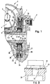
- a radial piston pump 1 is arranged in a gear housing 2.
- the transmission housing 2 also contains a starting device in the form of a hydrodynamic converter 3 with a guide wheel 4, a turbine wheel 5 and a pump wheel 6.
- the radial piston pump 1 connects directly to the converter 3. On the other side of the radial piston pump 1 is the actual transmission, of which only one shift brake 7 is partially shown.
- the stator 4 is mounted on a freewheel 8 on a stationary stator hollow shaft 10.
- An eccentric sliding bush 22, which is driven by a pin 13, is mounted on the stator hollow shaft 10.
- the pin 13 is designed as an axial extension of a pump shaft 14 connected to the pump wheel 6. Since the pump wheel 6 rotates at the engine speed, the eccentric sliding bush 22 is also driven at the engine speed.
- a sliding bush 23 and a sliding ring 24 between the eccentric sliding bush 22 and the piston 25.
- the pistons 25 are formed as deep-drawn parts and are held in contact with the slide ring 24 by the force of compression springs 26 with their radially inner piston head 27.
- the pistons 25 slide in cylinder bores 28 of a pump housing 29.
- the cylinder bores 28 are closed by plugs 30.
- Each stopper 30 is provided with a bore 31 and has two parallel grooves 32 on its end face, which run in the circumferential direction of the radial piston pump and which end within a machined sealing face 33 of the end face.
- a check valve is formed on each plug 30 in that all the plugs are surrounded by a common band spring 34.
- the band spring 34 seals the bores 31 and the grooves 32 with respect to a collecting ring groove 35 lying radially outside the plug 30.
- the collecting ring groove 35 also serves as an absorber space, which is arranged directly on the check valves.
- the pressure medium is fed from the collecting ring groove 35 to a lubrication device, not shown, and a control and actuation device of the transmission, also not shown, for example for actuating the shift brake 7.
- annular suction groove 37 is arranged in the pump housing 29 coaxially to the pump axis, which cuts the cylinder bores 28.
- the intersection between the suction annular groove 37 and the cylinder bores 28 forms suction openings 38.
- a suction throttle is formed on each piston 25 between the piston edge 36 and the respective suction opening 38.
Landscapes
- Engineering & Computer Science (AREA)
- General Engineering & Computer Science (AREA)
- Mechanical Engineering (AREA)
- Reciprocating Pumps (AREA)
- Lubrication Of Internal Combustion Engines (AREA)
- General Details Of Gearings (AREA)
- Rotary Pumps (AREA)
Abstract
Description
- Die Erfindung betrifft ein Getriebe, insbesondere Automatgetriebe oder stufenloses Getriebe, für Kraftfahrzeuge, mit einer Verdrängerpumpe für die Versorgung der Schmiereinrichtung und der Steuer- und Betätigungseinrichtungen des Getriebes, wobei die Verdrängerpumpe mit der Drehzahl eines Antriebsmotors angetrieben wird.
- Bei bekannten derartigen Getrieben sind die Pumpen sogenannte Konstantpumpen, deren Förderstrom proportional mit ihrer Antriebsdrehzahl ansteigt. Ein derartiges Getriebe ist aus der US-A-4 876 923 bekannt. Die Auslegung der Pumpe erfolgt im allgemeinen bei einer Leerlaufdrehzahl. Der dabei gelieferte Förderstrom muß bereits die Anforderungen des zu versorgenden Getriebes erfüllen.
- Eine derartige Pumpe fördert bei höheren Drehzahlen ein Mehrfaches der erforderlichen Menge. Die Kanalquerschnitte der Pumpe müssen deshalb stark überdimensioniert werden. Außerdem ergibt die damit zusammenhängende hohe Leistungsaufnahme der Pumpe einen schlechten Getriebewirkungsgrad.
- Der Erfindung liegt die Aufgabe zugrunde, das bekannte Getriebe derart zu verbessern, daß die Pumpe weniger Leistung aufnimmt und damit der Getriebe-Wirkungsgrad verbessert wird. Dazu soll die Pumpe eine kleine Ausdehnung in axialer Richtung aufweisen und einfache, preiswert herzustellende Teile enthalten.
- Diese Aufgabe wird durch das im Anspruch 1 gekennzeichnete Getriebe gelöst. Die Lösung besteht vor allem darin, daß die Verdrängerpumpe eine sauggedrosselte Radialkolbenpumpe ist.
- Während die Leistungsaufnahme von ungedrosselten Pumpen proportional mit der Fördermenge und damit mit der Drehzahl ansteigt, wird bei einer sauggedrosselten Pumpe ab einer bestimmten Drehzahl ein nahezu konstanter Förderstrom gefördert, der nur eine ebenso nahezu konstante Leistungsaufnahme erfordert. Eine sauggedrosselte Radialkolbenpumpe hat zusätzlich noch den Vorteil eines besseren volumetrischen Wirkungsgrades. Aufgrund der, auch bei hohen Drücken, nur geringen Leckage handelt es sich bei der Radialkolbenpumpe um eine sehr zuverlässige Pumpe. Eine sauggedrosselte Radialkolbenpumpe als solche ist aus der DE-C2-25 40 879 bekannt.
- Vorteilhafte und zweckmäßige Ausgestaltungen der Erfindung sind in den Unteransprüchen angegeben.
- Für einen einfachen Antrieb der Pumpe wird deren Antriebsteil zweckmäßigerweise mit einem Teil einer dem Getriebe vorgeschalteten Anfahreinrichtung verbunden. Der Exzenter der Radialkolbenpumpe wird vorteilhafterweise mit dem Pumpenrad eines hydrodynamischen Wandlers verbunden. Da die durch das Innere der Verdrängerpumpe hindurchgehende Welle im allgemeinen gehäusefest ist, wird der Exzenter der Radialkolbenpumpe als Exzentergleitbuchse ausgeführt, die über einen axial gerichteten Fortsatz der Pumpenwelle des Wandlers angetrieben wird.
- Werden die Kolben der Radialkolbenpumpe als Tiefziehteile ausgebildet, deren radial nach außen gerichteter Kolbenrand mit einer in einem Pumpengehäuse angeordneten Ansaug-Ringnut und deren Ansaugöffnungen zusammenarbeitet, so ergibt sich eine "oben ansaugende" Pumpe. Dies bedeutet, daß der Ansaugraum nicht im Inneren im Bereich des Exzenters liegt. Damit wird der Exzenterraum nicht mit dem im Kolbenraum entstehenden hohen Unterdruck beaufschlagt. Bei einer "unten ansaugenden" Kolbenpumpe müßte dieser Exzenterraum mit Öl befüllt sein. Wegen des großen Wellendurchmessers und des dadurch bedingten großen Dichtungsdurchmessers könnte über die Dichtung Luft nachgesaugt werden. Dieser Nachteil kann durch die erfindungsgemäße Anordnung vermieden werden, da hierbei der Exzenterraum nur einen Ölnebel zur Schmierung des Exzenters enthält. Die Ansaug-Ringnut läßt sich einfach in das Gehäuse einarbeiten und benötigt einen geringeren axialen Raum als die Anordnung von Einzelbohrungen und einer dazu erforderlichen Sammelringnut. Ebenso wird dabei die Ölführung zu dem Wandler vereinfacht.
- Die Zylinderbohrungen der Radialkolbenpumpe sind radial nach außen durch einen Stopfen verschlossen, deren Durchgangsbohrungen mit einer für alle Stopfen gemeinsamen Bandfeder als Rückschlagventile wirken. Um eine bessere Beaufschlagung der Bandfeder durch den Förderdruck zu erreichen, sind die Stopfen mit parallelen Rillen versehen, die innerhalb einer bearbeiteten Dichtfläche der Stirnflächen enden.
- Der Exzenter der Radialkolbenpumpe ist als Exzentergleitbuchse ausgeführt, die auf der feststehenden Hohlwelle geführt ist. Bei Verwendung eines hydrodynamischen Wandlers ist die Exzentergleitbuchse auf der Leitradhohlwelle gelagert.
- Im folgenden wird die Erfindung anhand eines in der Zeichnung dargestellten Ausführungsbeispieles näher erläutert.
- Es zeigt:
- Fig. 1
- das erfindungsgemäße Getriebe in einem Teilquerschnitt und
- Fig. 2
- einen Teilschnitt entsprechend der Linie II-II in Fig. 1, in vergrößertem Maßstab.
- Eine Radialkolbenpumpe 1 ist in einem Getriebegehäuse 2 angeordnet. Das Getriebegehäuse 2 enthält außerdem eine Anfahreinrichtung in der Form eines hydrodynamischen Wandlers 3 mit einem Leitrad 4, einem Turbinenrad 5 und einem Pumpenrad 6.
- Die Radialkolbenpumpe 1 schließt sich direkt an den Wandler 3 an. Auf der anderen Seite der Radialkolbenpumpe 1 liegt das eigentliche Getriebe, von dem nur eine Schaltbremse 7 teilweise dargestellt ist.
- Das Leitrad 4 ist über einen Freilauf 8 auf einer gehäusefesten Leitradhohlwelle 10 gelagert. Auf der Leitradhohlwelle 10 ist eine Exzentergleitbuchse 22 gelagert, die durch einen Zapfen 13 angetrieben wird. Der Zapfen 13 ist als axialer Fortsatz einer mit dem Pumpenrad 6 verbundenen Pumpenwelle 14 ausgebildet. Da das Pumpenrad 6 mit der Motordrehzahl dreht, wird auch die Exzentergleitbuchse 22 mit der Motordrehzahl angetrieben.
- Um die Reibung zu vermindern, ist es zweckmäßig, eine Gleitbuchse 23 und einen Gleitring 24 zwischen der Exzentergleitbuchse 22 und den Kolben 25 anzuordnen. Die Kolben 25 sind als Tiefziehteile ausgebildet und werden durch die Kraft von Druckfedern 26 mit ihrem radial innenliegenden Kolbenboden 27 in Anlage an dem Gleitring 24 gehalten. Die Kolben 25 gleiten in Zylinderbohrungen 28 eines Pumpengehäuses 29. Die Zylinderbohrungen 28 sind durch Stopfen 30 verschlossen. Jeder Stopfen 30 ist mit einer Bohrung 31 versehen und weist an seiner Stirnfläche zwei parallele Rillen 32 auf, die in Umfangsrichtung der Radialkolbenpumpe verlaufen und die innerhalb einer bearbeiteten Dichtfläche 33 der Stirnfläche enden. An jedem Stopfen 30 wird ein Rückschlagventil dadurch gebildet, daß alle Stopfen von einer gemeinsamen Bandfeder 34 umfaßt sind. Die Bandfeder 34 dichtet die Bohrungen 31 und die Rillen 32 gegenüber einer radial außerhalb der Stopfen 30 liegenden Sammelringnut 35 ab. Die Sammelringnut 35 dient gleichzeitig als Tilgerraum, der direkt an den Rückschlagventilen angeordnet ist. Bei Förderung der Radialkolbenpumpe 21 wird die Bandfeder 34 an denjenigen Stopfen 30 durch den Druck in der Bohrung 31 und in den Rillen 32 von der Dichtfläche 33 abgehoben, die in der Druckzone der Radialkolbenpumpe liegen.
- Von der Sammelringnut 35 wird das Druckmittel einer nicht dargestellten Schmiereinrichtung und einer ebenfalls nicht dargestellten Steuer- und Betätigungseinrichtung des Getriebes zugeleitet, beispielsweise zur Betätigung der Schaltbremse 7.
- Im Bereich des radial nach außen gerichteten Kolbenrandes 36 der Kolben 25 ist in dem Pumpengehäuse 29 koaxial zu der Pumpenachse eine Ansaug-Ringnut 37 angeordnet, die die Zylinderbohrungen 28 anschneidet. Durch die Verschneidung zwischen der Ansaug-Ringnut 37 und den Zylinderbohrungen 28 werden Ansaugöffnungen 38 gebildet. Zwischen dem Kolbenrand 36 und der jeweiligen Ansaugöffnung 38 wird an jedem Kolben 25 eine Saugdrossel gebildet.
-
- 1
- Radialkolbenpumpe
- 2
- Getriebegehäuse
- 3
- hydrodynamischer Wandler
- 4
- Leitrad
- 5
- Turbinenrad
- 6
- Pumpenrad
- 7
- Schaltbremse
- 8
- Freilauf
- 10
- Leitradhohlwelle
- 13
- Zapfen
- 14
- Pumpenwelle
- 22
- Exzentergleitbuchse
- 23
- Gleitbuchse
- 24
- Gleitring
- 25
- Kolben
- 26
- Druckfeder
- 27
- Kolbenboden
- 28
- Zylinderbohrung
- 29
- Pumpengehäuse
- 30
- Stopfen
- 31
- Bohrung
- 32
- Rille
- 33
- Dichtfläche
- 34
- Bandfeder
- 35
- Sammelringnut
- 36
- Kolbenrand
- 37
- Ansaug-Ringnut
- 38
- Ansaugöffnung
Claims (7)
- Getriebe, insbesondere Automatgetriebe oder stufenloses Getriebe, für Kraftfahrzeuge, mit einer Verdrängerpumpe für die Versorgung einer Schmiereinrichtung und/oder von Steuer- und Betätigungseinrichtungen des Getriebes, wobei die Verdrängerpumpe mit der Drehzahl des Antriebsmotors angetrieben wird, dadurch gekennzeichnet, daß die Verdrängerpumpe eine sauggedrosselte Radialkolbenpumpe (1) ist.
- Getriebe nach Anspruch 1, dadurch gekennzeichnet, daß die Radialkolbenpumpe (1) durch einen vorgeschalteten hydrodynamischen Wandler (3) angetrieben wird und daß der Exzenter der Radialkolbenpumpe (1) mit einem Pumpenrad (6) des Wandlers (3) verbunden ist.
- Getriebe nach Anspruch 2, dadurch gekennzeichnet, daß der Exzenter als Exzentergleitbuchse (22) ausgeführt ist, die über einen axial gerichteten Fortsatz der Pumpenwelle (14) des Wandlers angetrieben wird, und daß die Exzentergleitbuchse (22) auf einer Leitradhohlwelle (10) gelagert ist.
- Getriebe nach Anspruch 3, dadurch gekennzeichnet, daß die Exzentergleitbuchse (22) aus einem Gleitwerkstoff besteht.
- Getriebe nach Anspruch 1, dadurch gekennzeichnet,- daß die Kolben (25) der Radialkolbenpumpe (1) als Tiefziehteile ausgebildet sind, deren ihrem Kolbenboden (27) entgegengesetzter Kolbenrand (36) in der pumpe radial nach außen gerichtet ist;- daß durch die Verschneidung zwischen den Zylinderbohrungen (28) und einer koaxial zur Pumpenachse in einem Pumpengehäuse (29) angeordneten Ansaug-Ringnut (37) Ansaugöffnungen (38) gebildet sind, wobei die Ansaug-Ringnut (37) von dem Exzenterraum getrennt ist und- daß der Kolbenrand (36) und die Ansaugöffnungen (38) zusammen Saugdrosseln bilden.
- Getriebe nach Anspruch 5, dadurch gekennzeichnet,- daß jede Zylinderbohrung (28) der Radialkolbenpumpe (1) radial nach außen durch Stopfen (30) verschlossen ist,- daß jeder Stopfen (30) mit einer Bohrung (31) versehen ist und an seiner Stirnfläche parallele Rillen (32) aufweist, die in Umfangsrichtung der Radialkolbenpumpe (1) verlaufen und innerhalb einer bearbeiteten Dichtfläche (33) der Stirnfläche enden und- daß alle Stopfen (30) zur Bildung von Rückschlagventilen von einer gemeinsamen Bandfeder (34) umfaßt sind.
- Getriebe nach Anspruch 1, dadurch gekennzeichnet, daß die Kolben (25) der Radialkolbenpumpe (1) in einer ungleichmäßigen Winkelteilung angeordnet sind.
Applications Claiming Priority (3)
| Application Number | Priority Date | Filing Date | Title |
|---|---|---|---|
| DE4139611A DE4139611A1 (de) | 1991-11-30 | 1991-11-30 | Getriebe mit einer verdraengerpumpe |
| DE4139611 | 1991-11-30 | ||
| PCT/EP1992/002726 WO1993011376A1 (de) | 1991-11-30 | 1992-11-26 | Getriebe mit einer verdrängerpumpe |
Publications (3)
| Publication Number | Publication Date |
|---|---|
| EP0682756A1 EP0682756A1 (de) | 1995-11-22 |
| EP0682756B1 true EP0682756B1 (de) | 1997-01-29 |
| EP0682756B2 EP0682756B2 (de) | 1999-10-13 |
Family
ID=6446033
Family Applications (1)
| Application Number | Title | Priority Date | Filing Date |
|---|---|---|---|
| EP92923800A Expired - Lifetime EP0682756B2 (de) | 1991-11-30 | 1992-11-26 | Getriebe mit einer verdrängerpumpe |
Country Status (6)
| Country | Link |
|---|---|
| US (1) | US5645406A (de) |
| EP (1) | EP0682756B2 (de) |
| JP (1) | JPH07501601A (de) |
| DE (2) | DE4139611A1 (de) |
| ES (1) | ES2097933T5 (de) |
| WO (1) | WO1993011376A1 (de) |
Cited By (2)
| Publication number | Priority date | Publication date | Assignee | Title |
|---|---|---|---|---|
| DE10128431A1 (de) * | 2001-06-12 | 2002-12-19 | Zf Batavia Llc | Radialkolbenpumpe |
| US20250257723A1 (en) * | 2024-02-12 | 2025-08-14 | Dana Italia S.R.L. | Valveless, mechanical, pressure regulating pump |
Families Citing this family (31)
| Publication number | Priority date | Publication date | Assignee | Title |
|---|---|---|---|---|
| DE4224651C2 (de) * | 1992-07-25 | 2001-12-13 | Zf Batavia Llc | Getriebe mit einer Radialkolbenpumpe |
| DE4314217C2 (de) * | 1993-04-30 | 2001-10-11 | Zahnradfabrik Friedrichshafen | Radialkolbenpumpe |
| DE4332324A1 (de) * | 1993-09-23 | 1994-10-20 | Bosch Gmbh Robert | Radialkolbenmaschine |
| DE4336673C2 (de) * | 1993-10-27 | 1999-08-12 | Zahnradfabrik Friedrichshafen | Radialkolbenpumpe |
| HU216712B (hu) * | 1994-02-24 | 1999-08-30 | RÁBA Magyar Vagon- és Gépgyár Rt. | Speciális olajkeringető rendszer, főként nedvesfékes munkagépfutóművek és nagy terhelésű kerékagy-bolygóműves futóművek hűtésére |
| DE4435593A1 (de) * | 1994-10-05 | 1996-04-11 | Zahnradfabrik Friedrichshafen | Automatgetriebe mit einer Verdrängerpumpe |
| DE19748750A1 (de) | 1997-11-05 | 1999-05-06 | Zahnradfabrik Friedrichshafen | Radialkolbenpumpe |
| DE19750675C1 (de) | 1997-11-15 | 1998-08-13 | Zahnradfabrik Friedrichshafen | Ölpumpe |
| DE19849327B4 (de) * | 1998-10-26 | 2009-05-07 | Zf Friedrichshafen Ag | Lageranordnung |
| DE19908123A1 (de) * | 1999-02-25 | 2000-08-31 | Zahnradfabrik Friedrichshafen | Automatgetriebe |
| DE19930356A1 (de) * | 1999-07-01 | 2001-01-04 | Zahnradfabrik Friedrichshafen | Automatgetriebe |
| DE10102397A1 (de) | 2001-01-19 | 2002-07-25 | Zf Batavia Llc | Radialkolbenpumpe |
| DE10103014A1 (de) | 2001-01-24 | 2002-07-25 | Zf Batavia Llc | Radialkolbenpumpe |
| DE10103819A1 (de) * | 2001-01-29 | 2002-08-01 | Zf Lenksysteme Gmbh | Radialkolbenmaschine |
| US6461117B2 (en) * | 2001-02-27 | 2002-10-08 | International Truck Intellectual Property Company, L.L.C. | Reversible volume oil pump |
| DE10112951A1 (de) * | 2001-03-17 | 2002-09-19 | Zf Batavia Llc | Radialkolbenpumpe |
| DE10113649A1 (de) * | 2001-03-21 | 2002-09-26 | Zf Batavia Llc | Radialkolbenpumpe |
| DE10211083A1 (de) * | 2002-03-13 | 2003-11-27 | Zf Lenksysteme Gmbh | Getriebe |
| DE10227314A1 (de) * | 2002-06-19 | 2004-01-15 | Zf Friedrichshafen Ag | Pumpe |
| DE60323149D1 (de) | 2002-12-19 | 2008-10-02 | Bayer Cropscience Gmbh | Pflanzenzellen und pflanzen, die eine stärke mit erhöhter endviskosität synthetisieren |
| EP1548313B2 (de) † | 2003-12-23 | 2016-09-28 | Schaeffler Technologies AG & Co. KG | Drehmomentübertragungseinrichtung |
| DE102004004176A1 (de) * | 2004-01-28 | 2005-08-18 | Zf Friedrichshafen Ag | Hydrodynamischer Wandler eines Automatgetriebes für Kraftfahrzeuge |
| DE102004025764B4 (de) * | 2004-05-26 | 2018-09-13 | Zf Friedrichshafen Ag | Hydraulikkreislauf zur Ölversorgung eines Automat-, insbesondere eines Stufenautomatgetriebes für Kraftfahrzeuge |
| DE102004064331B3 (de) * | 2004-05-26 | 2020-12-03 | Zf Friedrichshafen Ag | Hydraulikkreislauf zur Ölversorgung eines Automatikgetriebes |
| DE102004035452A1 (de) * | 2004-07-22 | 2006-02-16 | Robert Bosch Gmbh | Kolbenpumpe mit verbesserter Druckaufbaudynamik |
| DE102004045425A1 (de) * | 2004-09-18 | 2006-04-06 | Zf Friedrichshafen Ag | Antriebsvorrichtung zum Antrieb einer Ölpumpe |
| US20080063554A1 (en) * | 2006-09-08 | 2008-03-13 | Gifford Thomas K | Precision flow gear pump |
| DE202008010126U1 (de) | 2008-07-29 | 2008-10-09 | Zf Friedrichshafen Ag | Ölpumpe eines automatisierten Kraftfahrzeug-Getriebes |
| DE102008035348B4 (de) | 2008-07-29 | 2016-10-13 | Zf Friedrichshafen Ag | Ölpumpe eines automatisierten Kraftfahrzeug-Getriebes |
| DE102012020705B4 (de) * | 2012-10-23 | 2022-10-27 | Arian Hoffmann | Kraftfahrzeuggetriebevorrichtung mit einer Getriebeölpumpe |
| DE102022134016B4 (de) * | 2022-12-20 | 2024-07-04 | Schaeffler Technologies AG & Co. KG | Ölpumpe für Getriebe eines Elektrofahrzeugs |
Family Cites Families (31)
| Publication number | Priority date | Publication date | Assignee | Title |
|---|---|---|---|---|
| US2021182A (en) * | 1933-04-26 | 1935-11-19 | Axel E Hedlund | Hydraulic clutch and power transmission |
| US2423701A (en) * | 1945-01-01 | 1947-07-08 | Marquette Metal Products Co | Pump |
| US3293945A (en) * | 1963-12-30 | 1966-12-27 | Ford Motor Co | Infinitely variable speed transmission |
| US3385059A (en) * | 1966-10-12 | 1968-05-28 | Ford Motor Co | Hyperlinear hydrostatic power transmission system having both linear and hyperbolic characteristics |
| DE2103645A1 (de) * | 1971-01-27 | 1972-08-17 | Robert Bosch Gmbh, 7000 Stuttgart | Kolbenpumpe, insbesondere Radialkolbenpumpe |
| US3728046A (en) * | 1971-10-06 | 1973-04-17 | Trw Inc | Power steering pump |
| US3724205A (en) * | 1971-12-01 | 1973-04-03 | Borg Warner | Automatic transmission control system |
| DE2242435C3 (de) * | 1972-08-29 | 1981-09-24 | Alfred Teves Gmbh, 6000 Frankfurt | Radialkolbenpumpe |
| SE379915B (de) * | 1973-02-09 | 1975-10-20 | Asea Ab | |
| JPS53134168A (en) * | 1977-04-28 | 1978-11-22 | Toyota Motor Corp | Breather device in automatic transmission gear box |
| US4181203A (en) * | 1978-08-14 | 1980-01-01 | General Motors Corporation | Control for a torque converter slipping clutch |
| DE2901240C2 (de) * | 1979-01-13 | 1981-10-01 | Zahnradfabrik Friedrichshafen Ag, 7990 Friedrichshafen | Radialkolbenpumpe |
| US4339234A (en) * | 1979-08-03 | 1982-07-13 | Lucas Industries Limited | Drive cam and follower for a liquid fuel injection pumping apparatus |
| DE3005657C2 (de) * | 1980-02-15 | 1987-01-02 | Zahnradfabrik Friedrichshafen Ag, 7990 Friedrichshafen | Zahnradpumpe |
| FR2517396B1 (fr) * | 1981-11-30 | 1987-02-20 | Glyco Antriebstechnik Gmbh | Embrayage hydrostatique |
| DE3513164A1 (de) * | 1985-04-12 | 1986-10-23 | Robert Bosch Gmbh, 7000 Stuttgart | Radialkolbenpumpe |
| DE3517929A1 (de) * | 1985-05-18 | 1986-11-20 | Robert Bosch Gmbh, 7000 Stuttgart | Kolbenpumpe |
| US4850937A (en) * | 1987-05-28 | 1989-07-25 | Fuji Jukogyo Kabushiki Kaisha | System for controlling the pressure of oil for a continuously variable transmission |
| DE3726979A1 (de) * | 1987-08-13 | 1989-02-23 | Opel Adam Ag | Hydraulikeinheit fuer ein kraftfahrzeug |
| JPH0216370A (ja) * | 1988-07-01 | 1990-01-19 | Kayaba Ind Co Ltd | ラジアルピストンポンプ |
| US4876923A (en) * | 1988-07-11 | 1989-10-31 | Ford Motor Company | Torque converter lockup clutch control for an automatic transmission |
| US5156531A (en) * | 1988-09-15 | 1992-10-20 | Zahnradfabrik Friedrichshafen, Ag. | Radial piston pump |
| DE8912797U1 (de) * | 1989-10-28 | 1989-12-28 | Vickers Systems GmbH, 6380 Bad Homburg | Radialkolbenpumpe |
| DE4010090A1 (de) * | 1990-03-29 | 1991-10-02 | Bosch Gmbh Robert | Hubkolbenpumpe |
| DE4027848A1 (de) * | 1990-09-03 | 1992-03-05 | Teves Gmbh Alfred | Kolbenpumpe |
| DE4135904A1 (de) * | 1990-11-06 | 1992-05-21 | Teves Gmbh Alfred | Kolbenpumpe, insbesondere radialkolbenpumpe |
| US5167493A (en) * | 1990-11-22 | 1992-12-01 | Nissan Motor Co., Ltd. | Positive-displacement type pump system |
| DE4135377A1 (de) * | 1991-10-26 | 1993-04-29 | Bosch Gmbh Robert | Hydraulische steuereinrichtung |
| DE4135380A1 (de) * | 1991-10-26 | 1993-04-29 | Bosch Gmbh Robert | Hydraulische steuereinrichtung |
| DE4211931C1 (en) * | 1992-04-09 | 1993-09-02 | Julius Montz Gmbh, 4010 Hilden, De | Precisely adjustable liq. flow divider - for partial liq. recycle to countercurrent column |
| DE4314217C2 (de) * | 1993-04-30 | 2001-10-11 | Zahnradfabrik Friedrichshafen | Radialkolbenpumpe |
-
1991
- 1991-11-30 DE DE4139611A patent/DE4139611A1/de not_active Withdrawn
-
1992
- 1992-11-26 ES ES92923800T patent/ES2097933T5/es not_active Expired - Lifetime
- 1992-11-26 DE DE59208002T patent/DE59208002D1/de not_active Expired - Lifetime
- 1992-11-26 WO PCT/EP1992/002726 patent/WO1993011376A1/de not_active Ceased
- 1992-11-26 EP EP92923800A patent/EP0682756B2/de not_active Expired - Lifetime
- 1992-11-26 US US08/244,534 patent/US5645406A/en not_active Expired - Lifetime
- 1992-11-26 JP JP5509802A patent/JPH07501601A/ja active Pending
Cited By (2)
| Publication number | Priority date | Publication date | Assignee | Title |
|---|---|---|---|---|
| DE10128431A1 (de) * | 2001-06-12 | 2002-12-19 | Zf Batavia Llc | Radialkolbenpumpe |
| US20250257723A1 (en) * | 2024-02-12 | 2025-08-14 | Dana Italia S.R.L. | Valveless, mechanical, pressure regulating pump |
Also Published As
| Publication number | Publication date |
|---|---|
| ES2097933T3 (es) | 1997-04-16 |
| WO1993011376A1 (de) | 1993-06-10 |
| EP0682756B2 (de) | 1999-10-13 |
| JPH07501601A (ja) | 1995-02-16 |
| EP0682756A1 (de) | 1995-11-22 |
| DE4139611A1 (de) | 1993-06-03 |
| DE59208002D1 (de) | 1997-03-13 |
| ES2097933T5 (es) | 2000-02-01 |
| US5645406A (en) | 1997-07-08 |
Similar Documents
| Publication | Publication Date | Title |
|---|---|---|
| EP0682756B2 (de) | Getriebe mit einer verdrängerpumpe | |
| EP0254077B1 (de) | Innenzahnradpumpe | |
| DE19542653C2 (de) | Automatikgetriebe für ein motorbetriebenes Fahrzeug | |
| EP0712997A2 (de) | Ventilsteuerung mit sauggeregelter Zahnring-/Innenzahnradpumpe | |
| EP0533720B1 (de) | Antriebsvorrichtung | |
| EP0839283B1 (de) | Ölgedichtete drehschiebervakuumpumpe mit einer ölversorgung | |
| DE102011108767B4 (de) | Hocheffiziente Drehschieberkonstantpumpe | |
| DE60031459T2 (de) | Gerotormotor mit Schmiernuten | |
| EP1685328B1 (de) | Doppel- oder mehrfachpumpe | |
| EP0784764B1 (de) | Automatgetriebe mit einer verdrängerpumpe | |
| EP0134211B1 (de) | Pumpenanordnung für hydraulische anlagen | |
| DE3303856C2 (de) | Rotationszellenpumpe | |
| EP0475109B1 (de) | Innenzahnradpumpe für Hydraulikflüssigkeit | |
| EP0473025B1 (de) | Innenzahnradpumpe für Hydraulikflüssigkeit | |
| EP0474001B1 (de) | Innenzahnradpumpe für Hydraulikflüssigkeit | |
| EP2137412B1 (de) | Verdrängermaschine nach dem spiralprinzip | |
| EP0315878B1 (de) | Innenzahnradpumpe | |
| DE3737961A1 (de) | Innenzahnradpumpe | |
| DE4033105A1 (de) | Hydraulikanlage | |
| DE2639127A1 (de) | Drehkolbenvorrichtung | |
| DE2219587A1 (de) | Fluegelzellenpumpe | |
| DE4312053A1 (de) | Getriebe mit einer Verdrängerpumpe | |
| DE19859761A1 (de) | Automatikgetriebe | |
| DE19514749A1 (de) | Hydrostatische Radialkolbenpumpe | |
| DE3624382A1 (de) | Exzentrische sperrschieberpumpe, insbesondere zur foerderung von schmierstoffen fuer antriebe |
Legal Events
| Date | Code | Title | Description |
|---|---|---|---|
| PUAI | Public reference made under article 153(3) epc to a published international application that has entered the european phase |
Free format text: ORIGINAL CODE: 0009012 |
|
| 17P | Request for examination filed |
Effective date: 19940330 |
|
| AK | Designated contracting states |
Kind code of ref document: A1 Designated state(s): DE ES FR GB |
|
| 17Q | First examination report despatched |
Effective date: 19951218 |
|
| GRAG | Despatch of communication of intention to grant |
Free format text: ORIGINAL CODE: EPIDOS AGRA |
|
| GRAH | Despatch of communication of intention to grant a patent |
Free format text: ORIGINAL CODE: EPIDOS IGRA |
|
| GRAH | Despatch of communication of intention to grant a patent |
Free format text: ORIGINAL CODE: EPIDOS IGRA |
|
| GRAA | (expected) grant |
Free format text: ORIGINAL CODE: 0009210 |
|
| AK | Designated contracting states |
Kind code of ref document: B1 Designated state(s): DE ES FR GB |
|
| GBT | Gb: translation of ep patent filed (gb section 77(6)(a)/1977) |
Effective date: 19970207 |
|
| REF | Corresponds to: |
Ref document number: 59208002 Country of ref document: DE Date of ref document: 19970313 |
|
| REG | Reference to a national code |
Ref country code: ES Ref legal event code: FG2A Ref document number: 2097933 Country of ref document: ES Kind code of ref document: T3 |
|
| ET | Fr: translation filed | ||
| PLAV | Examination of admissibility of opposition |
Free format text: ORIGINAL CODE: EPIDOS OPEX |
|
| PLBI | Opposition filed |
Free format text: ORIGINAL CODE: 0009260 |
|
| 26 | Opposition filed |
Opponent name: LUK FAHRZEUG-HYDRAULIK GMBH & CO. KG Effective date: 19971029 |
|
| PLAV | Examination of admissibility of opposition |
Free format text: ORIGINAL CODE: EPIDOS OPEX |
|
| PLBF | Reply of patent proprietor to notice(s) of opposition |
Free format text: ORIGINAL CODE: EPIDOS OBSO |
|
| PLBF | Reply of patent proprietor to notice(s) of opposition |
Free format text: ORIGINAL CODE: EPIDOS OBSO |
|
| PLBF | Reply of patent proprietor to notice(s) of opposition |
Free format text: ORIGINAL CODE: EPIDOS OBSO |
|
| PLBQ | Unpublished change to opponent data |
Free format text: ORIGINAL CODE: EPIDOS OPPO |
|
| PGFP | Annual fee paid to national office [announced via postgrant information from national office to epo] |
Ref country code: ES Payment date: 19981113 Year of fee payment: 7 |
|
| PLAB | Opposition data, opponent's data or that of the opponent's representative modified |
Free format text: ORIGINAL CODE: 0009299OPPO |
|
| R26 | Opposition filed (corrected) |
Opponent name: LUK FAHRZEUG-HYDRAULIK GMBH & CO. KG Effective date: 19971029 |
|
| PLAW | Interlocutory decision in opposition |
Free format text: ORIGINAL CODE: EPIDOS IDOP |
|
| PLAW | Interlocutory decision in opposition |
Free format text: ORIGINAL CODE: EPIDOS IDOP |
|
| PUAH | Patent maintained in amended form |
Free format text: ORIGINAL CODE: 0009272 |
|
| STAA | Information on the status of an ep patent application or granted ep patent |
Free format text: STATUS: PATENT MAINTAINED AS AMENDED |
|
| 27A | Patent maintained in amended form |
Effective date: 19991013 |
|
| AK | Designated contracting states |
Kind code of ref document: B2 Designated state(s): DE ES FR GB |
|
| PGFP | Annual fee paid to national office [announced via postgrant information from national office to epo] |
Ref country code: GB Payment date: 19991020 Year of fee payment: 8 |
|
| PGFP | Annual fee paid to national office [announced via postgrant information from national office to epo] |
Ref country code: FR Payment date: 19991117 Year of fee payment: 8 |
|
| ET3 | Fr: translation filed ** decision concerning opposition | ||
| GBTA | Gb: translation of amended ep patent filed (gb section 77(6)(b)/1977) |
Effective date: 19991215 |
|
| REG | Reference to a national code |
Ref country code: ES Ref legal event code: DC2A Kind code of ref document: T5 Effective date: 19991213 |
|
| PG25 | Lapsed in a contracting state [announced via postgrant information from national office to epo] |
Ref country code: GB Free format text: LAPSE BECAUSE OF NON-PAYMENT OF DUE FEES Effective date: 20001126 |
|
| PG25 | Lapsed in a contracting state [announced via postgrant information from national office to epo] |
Ref country code: ES Free format text: LAPSE BECAUSE OF NON-PAYMENT OF DUE FEES Effective date: 20001127 |
|
| GBPC | Gb: european patent ceased through non-payment of renewal fee |
Effective date: 20001126 |
|
| PG25 | Lapsed in a contracting state [announced via postgrant information from national office to epo] |
Ref country code: FR Free format text: LAPSE BECAUSE OF NON-PAYMENT OF DUE FEES Effective date: 20010731 |
|
| REG | Reference to a national code |
Ref country code: FR Ref legal event code: ST |
|
| REG | Reference to a national code |
Ref country code: ES Ref legal event code: FD2A Effective date: 20011214 |
|
| PGFP | Annual fee paid to national office [announced via postgrant information from national office to epo] |
Ref country code: DE Payment date: 20101124 Year of fee payment: 19 |
|
| REG | Reference to a national code |
Ref country code: DE Ref legal event code: R071 Ref document number: 59208002 Country of ref document: DE |
|
| REG | Reference to a national code |
Ref country code: DE Ref legal event code: R071 Ref document number: 59208002 Country of ref document: DE |