EP0677467A2 - Procédé pour transporter/traiter des substrats plats individuels - Google Patents
Procédé pour transporter/traiter des substrats plats individuels Download PDFInfo
- Publication number
- EP0677467A2 EP0677467A2 EP95104247A EP95104247A EP0677467A2 EP 0677467 A2 EP0677467 A2 EP 0677467A2 EP 95104247 A EP95104247 A EP 95104247A EP 95104247 A EP95104247 A EP 95104247A EP 0677467 A2 EP0677467 A2 EP 0677467A2
- Authority
- EP
- European Patent Office
- Prior art keywords
- sheet
- section
- sensor
- transport
- sheets
- Prior art date
- Legal status (The legal status is an assumption and is not a legal conclusion. Google has not performed a legal analysis and makes no representation as to the accuracy of the status listed.)
- Ceased
Links
Images

Classifications
-
- B—PERFORMING OPERATIONS; TRANSPORTING
- B65—CONVEYING; PACKING; STORING; HANDLING THIN OR FILAMENTARY MATERIAL
- B65H—HANDLING THIN OR FILAMENTARY MATERIAL, e.g. SHEETS, WEBS, CABLES
- B65H3/00—Separating articles from piles
- B65H3/08—Separating articles from piles using pneumatic force
- B65H3/0808—Suction grippers
- B65H3/0816—Suction grippers separating from the top of pile
-
- B—PERFORMING OPERATIONS; TRANSPORTING
- B65—CONVEYING; PACKING; STORING; HANDLING THIN OR FILAMENTARY MATERIAL
- B65H—HANDLING THIN OR FILAMENTARY MATERIAL, e.g. SHEETS, WEBS, CABLES
- B65H5/00—Feeding articles separated from piles; Feeding articles to machines
- B65H5/34—Varying the phase of feed relative to the receiving machine
-
- B—PERFORMING OPERATIONS; TRANSPORTING
- B65—CONVEYING; PACKING; STORING; HANDLING THIN OR FILAMENTARY MATERIAL
- B65H—HANDLING THIN OR FILAMENTARY MATERIAL, e.g. SHEETS, WEBS, CABLES
- B65H2511/00—Dimensions; Position; Numbers; Identification; Occurrences
- B65H2511/10—Size; Dimensions
- B65H2511/11—Length
-
- B—PERFORMING OPERATIONS; TRANSPORTING
- B65—CONVEYING; PACKING; STORING; HANDLING THIN OR FILAMENTARY MATERIAL
- B65H—HANDLING THIN OR FILAMENTARY MATERIAL, e.g. SHEETS, WEBS, CABLES
- B65H2511/00—Dimensions; Position; Numbers; Identification; Occurrences
- B65H2511/20—Location in space
-
- B—PERFORMING OPERATIONS; TRANSPORTING
- B65—CONVEYING; PACKING; STORING; HANDLING THIN OR FILAMENTARY MATERIAL
- B65H—HANDLING THIN OR FILAMENTARY MATERIAL, e.g. SHEETS, WEBS, CABLES
- B65H2511/00—Dimensions; Position; Numbers; Identification; Occurrences
- B65H2511/50—Occurence
- B65H2511/51—Presence
- B65H2511/514—Particular portion of element
-
- B—PERFORMING OPERATIONS; TRANSPORTING
- B65—CONVEYING; PACKING; STORING; HANDLING THIN OR FILAMENTARY MATERIAL
- B65H—HANDLING THIN OR FILAMENTARY MATERIAL, e.g. SHEETS, WEBS, CABLES
- B65H2513/00—Dynamic entities; Timing aspects
- B65H2513/50—Timing
Definitions
- the invention relates to a method for transporting / processing individual flat substrates along at least one transport / processing section or the like - hereinafter referred to as section - in a machine, in particular for feeding and removing sheets to be printed on / from at least one printing unit Sheet printing machine, the period in the section for the transport / processing or the like of successive substrates depending on the longitudinal format of the substrates, according to German patent application P 44 13 238.7.
- a single, flat substrate is to be understood as a surface element that can be designed, for example, as an arc. If, therefore, the term "arch” is used in the context of this application, this term always means the generic term, namely "substrate".
- the above-mentioned method which relates to the German patent application P 44 13 238, has the advantage that the speed in the substrate transport / substrate processing customary in the prior art is no longer given due to a corresponding machine cycle. Due to this procedure, there is a very high degree of flexibility in that the distances or periods between successive substrates are no longer fixed to a maximum longitudinal format, in order then to increase accordingly as the longitudinal format becomes smaller, but can be specified in such a way that even with a smaller one Format these distances or keep the distance times or even selected accordingly, in particular can be reduced.
- the invention has for its object to further specify the above-mentioned method.
- At least one substrate position determination is carried out in the section and in that a new substrate is introduced into the section as soon as the rear edge of the substrate of the predecessor substrate has reached a certain position.
- "Spacing" means a corresponding, predetermined size between the trailing edge of the previous sheet and the leading edge of the new sheet and also includes - if desired - the distance "O" between adjacent sheets.
- sheets of a sheet processing machine in particular a sheet printing machine, are used as the substrate or substrates.
- the sheet position can be determined in particular by means of a sensor (first sheet sensor).
- the sheet position determination can preferably be done by Detection of the leading edge of the sheet can be made.
- the position of the trailing edge of the sheet can be calculated.
- the sheet length can also be determined by measuring a test sheet, the measurement and the entry of the sheet length into the control device being carried out either manually or automatically.
- the new sheet is introduced when the sheet trailing edge of the previous sheet is recognized by means of sheet length detection and the position has been calculated.
- At least one further, second sheet position detection is carried out in the section by means of which - in the case of feeding the sheets to one Sheet printing machine - the subject of a rewritable, in particular digitally controllable printing cylinder is controlled. Due to this measure, the imaging of the printing unit is controlled in accordance with the formats of the incoming sheets, so that the closely sequential sheet stream is printed without gaps or gaps, regardless of the fact that the printing cylinder has a fixed predetermined diameter and thus a fixed scope, because of the Rewritable, it is possible to continuously change the subject over the circumference of the printing cylinder in such a way that the incoming sheet can be optimally printed regardless of the format.
- the position of the leading edge of the corresponding sheet is determined in the further sheet position detection.
- a single sheet can be introduced into the section, whereby a single sheet can be inserted in a single sheet position, in which it is recognized by means of a third sheet position determination and, based on the results of the sheet position detection and / or sheet position detection, is introduced into the section between a previous sheet and a new sheet in a defined manner .
- Predecessor sheets and new sheets preferably originate from an installation stack and are continuously separated from the sheet stack with a corresponding device, for example a suction arrangement, and then fed to the section. Irrespective of this, the single sheet injection mentioned provides that a single sheet is seamlessly introduced into this sheet stream coming from the sheet stack, that is, it fits into the sheet stream as well as a sheet originating from the sheet stack.
- the single sheet is brought into the single sheet position, where it is then recognized by means of the third sheet position determination.
- the sheet stream emanating from the sheet stack is interrupted by means of the sheet transport detection and / or sheet position detection, that is to say the corresponding sheets are briefly stopped in such a way that the single sheet is introduced into the section from its single sheet feed position, its leading edge correspondingly to the trailing edge the previous sheet is positioned, as is the case in "normal operation” and that the leading edge of the following new sheet, namely from the sheet stack, adjoins the rear edge of the inserted sheet.
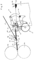
- FIG. 1 shows - in a schematic representation - a sheet-fed printing machine 1 which has a feeder 2 and a delivery arm 3.
- Printing units 4 are arranged between feeder 2 and delivery arm 3.
- the printing units 4 have printing cylinders 5, which are designed as rewritable printing cylinders, that is to say a large number of closely spaced pixels, which can be controlled digitally, are arranged over the outer surface of the corresponding printing cylinders, with either printing ink being accepted or no printing ink depending on the control Is accepted.
- This means that the subject to be printed can be created in a fraction of a second using digital electronics and - during the rotation of the printing cylinders - changed. In this way, it is possible to print on the substrate in the desired manner, continuously Subject changes can be made and / or different formats can also be printed.
- a stack of sheets 6 is assigned to the feeder 2, from which sheets 7 are removed by means of a suction arrangement 8 and fed to a transport section 9, by means of which the sheets are then fed to the individual printing units 4 and finally reach the delivery 3, where they are placed on a sheet stack 10.
- the computer symbol 11 in FIG. 1 indicates that the actuation of the printing cylinder 5 is carried out digitally in the manner described above.
- the configuration of the suction arrangement 8 of the transport section 9 is shown in detail in FIG. It can be seen that the suction arrangement 8 has a suction rod 12 which interacts with suction devices 13, the suction devices 13 being driven by a control gear 15 - driven by a control shaft 15 - in such a way that they separate the sheets 7 of the sheet stack 6 suck in the sheet lying on top and - with its leading edge 16 ahead - feed it to the transport section 9.
- the control shaft 15 represents a first drive 17.
- the transport section 9 has two opposing acceleration rollers 18, which can be driven by means of a second drive 19, not shown in FIG. 2.
- the acceleration rollers 18 are followed by a sheet guide 20 which opens into an opening 21 of a further, second sheet guide 22 coming obliquely from above.
- opposing transport rollers 23 are arranged, which are driven by a third drive 24, not shown.
- a third sheet guide 25 connects to the transport rollers 23, which leads to a printing unit of the sheet-fed printing press, which is provided by cylinders 26 is shown.
- the second sheet guide 22 leads to a single sheet feeder 27, onto which single sheets, i.e.
- the aforementioned single sheet feeder 27 can alternatively or additionally also be designed as a second sheet stack corresponding to the sheet stack 6, so that the sheet printing machine 1 works with two stacks.
- a first sheet sensor 29 is arranged between the acceleration rollers 18 and the transport rollers 23, for example in the initial areas of the sheet guide 20, which detects the sheet leading edges 16 from sheets 7 arriving there as they pass through the transport section 9.
- the position of the sheet trailing edges 30 is calculated in each case via the sheet leading edge position and the sheet length. This makes it possible in particular to achieve a "zero" distance between adjacent sheets 7.
- the sheet length is determined by means of a length sensor 35 assigned to the sheet stack 6 or manually entered into a control device. It is also possible to measure a sheet 7 during a test run by means of the sheet sensor 29 or a further, second sheet sensor 31. By knowing the position of the leading edge of the sheet and the length of the sheet, the position of the trailing edge of the sheet is always determined.
- the second sheet sensor 31 Seen in the direction of transport, the second sheet sensor 31 already mentioned is located behind the transport rollers 23, preferably in the starting area of the third sheet guide 25. The second sheet sensor 31 determines the exact position of the leading edges 16 of the incoming sheets 7 there.
- the single sheet feeder 27 is a third sheet sensor 32 assigned, which is able to recognize sheets 7 placed on the single sheet feeder 27.
- the suction arrangement 8 lifts the uppermost sheet 7 from the sheet stack 6 and guides its front edge 16 between the accelerating rollers 18, so that the sheet 7 is transported into the sheet guide 20.
- the first sheet sensor 29 picks up the front edge 16 of the sheet 7.
- the suction arrangement 8 is controlled in such a way that a new sheet 7 is separated and fed to the accelerating rollers 18 as soon as the rear edge of the preceding sheet 7 has left the area of the suction arrangement 8.
- the acceleration rollers 18 accelerate the new sheet until its front edge 16 reaches the rear edge 30 of the preceding sheet 7.
- the described process of introducing new sheets 7 into the transport section 9 is repeated continuously in the manner described above.
- the second sheet sensor 31 determines the exact position of the leading edge 16 of the incoming sheet 7 during operation and controls the printing cylinder 5 of the sheet printing machine 1 accordingly, so that the subject to be transferred is available in the desired manner as soon as the associated sheet reaches the printing units . Since these are rewritable printing units that are controlled electronically, the subject formation on the printing cylinders is controlled according to the desired print image and depending on the incoming sheet format - even successive sheets can have a different format. This format adjustment takes place not only with regard to the printing cylinders of the printing units, but also with regard to the components of the transport section.
- the three drives 17, 19 and 24 mentioned are provided with separate motors, so that they can be controlled individually, so that - depending on the desired result and the present sheet format - the feeder control of the suction arrangement 8, the Control and operate the accelerating rollers 18 and the transport rollers 23 independently of one another.
- the third sheet sensor 32 detects this, and - at the right moment - controls the single sheet sheet drive 28 in such a way that the single sheet 7 thus detected passes the second sheet guide 22 and by means of the junction 21 into the end region of the Bow guide 20 is introduced. This is done in such a way that the leading edge 16 of the inserted sheet reaches the trailing edge 30 of the preceding sheet 7, which comes from the sheet stack 6. During the introduction, there is no subsequent delivery of new sheets 7 from the sheet stack 6. This is suspended until the feeding of a new sheet 7 from the sheet stack 6 can take place in such a way that its leading edge 16 by means of the accelerating roller 18 up to the sheet trailing edge 30 of the introduced sheet 7 can be introduced.
- the highest degree of effectiveness and tight sheet sequence is achieved by the sheet travel control according to the invention, whereby the time for determining the machine productivity, which is determining the machine productivity, can be significantly increased by accelerating the sheets 7. This increases the bow frequency.
- delivery takes place closely to one another, i.e. sheet on sheet, so that it is no longer possible to speak of the size of the print / hour but of the meter / hour. It is possible to process constantly changing sheet formats. Parts that require a great deal of effort, for example the high energy consumption of the blown air, which is required for the blowing and thus for guiding the sheets 7, are used much better due to the design according to the invention.
Landscapes
- Engineering & Computer Science (AREA)
- Mechanical Engineering (AREA)
- Inking, Control Or Cleaning Of Printing Machines (AREA)
- Registering Or Overturning Sheets (AREA)
- Controlling Sheets Or Webs (AREA)
- Delivering By Means Of Belts And Rollers (AREA)
- Feeding Of Articles By Means Other Than Belts Or Rollers (AREA)
- Separation, Sorting, Adjustment, Or Bending Of Sheets To Be Conveyed (AREA)
Applications Claiming Priority (4)
| Application Number | Priority Date | Filing Date | Title |
|---|---|---|---|
| DE4413238 | 1994-04-15 | ||
| DE4413238A DE4413238B4 (de) | 1994-04-15 | 1994-04-15 | Verfahren zum Zu- und Abführen von zu bedruckenden/bedruckten Bogen zu/von mindestens einem Druckwerk einer Bogendruckmaschine |
| DE19508254 | 1995-03-08 | ||
| DE19508254.0A DE19508254C5 (de) | 1994-04-15 | 1995-03-08 | Verfahren zum Transportieren von einzelnen Bogen |
Publications (2)
| Publication Number | Publication Date |
|---|---|
| EP0677467A2 true EP0677467A2 (fr) | 1995-10-18 |
| EP0677467A3 EP0677467A3 (fr) | 1996-10-23 |
Family
ID=25935695
Family Applications (1)
| Application Number | Title | Priority Date | Filing Date |
|---|---|---|---|
| EP95104247A Ceased EP0677467A3 (fr) | 1994-04-15 | 1995-03-23 | Procédé pour transporter/traiter des substrats plats individuels. |
Country Status (4)
| Country | Link |
|---|---|
| US (1) | US5775683A (fr) |
| EP (1) | EP0677467A3 (fr) |
| JP (1) | JPH07304539A (fr) |
| DE (1) | DE19508254C5 (fr) |
Cited By (3)
| Publication number | Priority date | Publication date | Assignee | Title |
|---|---|---|---|---|
| EP0841272A1 (fr) * | 1996-10-09 | 1998-05-13 | SHARP Corporation | Dispositif d'alimentation et de sortie de feuilles |
| EP1013580A1 (fr) * | 1998-12-23 | 2000-06-28 | Xerox Corporation | Rouleaux d'enlèvement à accélération variable pour un dispositif d'alimentation en feuilles à grande capacité |
| US6609708B2 (en) | 1998-12-23 | 2003-08-26 | Xerox Corporation | Vacuum corrugation shuttle feed device for high capacity feeder |
Families Citing this family (5)
| Publication number | Priority date | Publication date | Assignee | Title |
|---|---|---|---|---|
| JP2000191151A (ja) * | 1998-12-23 | 2000-07-11 | Xerox Corp | シ―トの角度および高さを制御する方法 |
| US6186492B1 (en) * | 1998-12-23 | 2001-02-13 | Xerox Corporation | Adjusting air system pressures stack height and lead edge gap in high capacity feeder |
| US6126160A (en) * | 1999-04-12 | 2000-10-03 | Eastman Kodak Company | Sheet feeding control for image reading device |
| US20020168250A1 (en) * | 2001-05-10 | 2002-11-14 | Welch Stephen R. | Method and apparatus for forming a binder cover and ring binder |
| JP2003155130A (ja) * | 2001-11-20 | 2003-05-27 | Brother Ind Ltd | 画像形成装置 |
Citations (1)
| Publication number | Priority date | Publication date | Assignee | Title |
|---|---|---|---|---|
| DE4413238A1 (de) | 1994-04-15 | 1995-10-19 | Heidelberger Druckmasch Ag | Verfahren zum Transportieren/Bearbeiten von Bogen |
Family Cites Families (24)
| Publication number | Priority date | Publication date | Assignee | Title |
|---|---|---|---|---|
| US2561030A (en) * | 1947-04-02 | 1951-07-17 | Addressograph Multigraph | Sheet feeding apparatus |
| GB918008A (en) * | 1960-06-28 | 1963-02-13 | Nederlanden Staat | Apparatus for separating and conveying sheet-like articles |
| DE1183100B (de) * | 1960-06-28 | 1964-12-10 | Nederlanden Staat | Bogenzufuehreinrichtung zum Vereinzeln und Abtransportieren des jeweils obersten Bogens eines Blattstapels |
| DE2230421A1 (de) * | 1972-06-22 | 1974-01-10 | Oppenweiler Binder & Co Maschb | Vorrichtung zur steuerung der bogenzufuehrung an bogenanlegern |
| DD112411A5 (fr) * | 1973-05-14 | 1975-04-12 | ||
| DE2758007C2 (de) * | 1977-12-24 | 1979-10-25 | Licentia Patent-Verwaltungs-Gmbh, 6000 Frankfurt | Verfahren zum Steuern des Abzugsvorgangs bei einer Einrichtung zur Abgabe vereinzelter Sendungen von unterschiedlicher Länge sowie entsprechende Einrichtung |
| US4318540A (en) * | 1978-09-14 | 1982-03-09 | Burroughs Corporation | Constant spacing document feeder |
| US4451027A (en) * | 1980-01-09 | 1984-05-29 | Burroughs Corp. | Constant spacing document feeder |
| US4331328A (en) * | 1980-06-30 | 1982-05-25 | Burroughs Corporation | Controller for a servo driven document feeder |
| JPS5767431A (en) * | 1980-10-09 | 1982-04-24 | Canon Inc | Feeding device |
| US4541624A (en) * | 1982-03-24 | 1985-09-17 | Nippon Electric Co., Ltd. | Flat article feeding apparatus |
| US4824090A (en) * | 1982-11-26 | 1989-04-25 | Xerox Corporation | Automatically setting the paper path components of a reproduction machine in accordance with the size copy sheet being processed |
| JPS6048054A (ja) * | 1983-08-26 | 1985-03-15 | Toshiba Corp | 給紙装置 |
| JPS6061459A (ja) * | 1983-09-14 | 1985-04-09 | Canon Inc | シ−ト材の給送装置 |
| CH670618A5 (fr) * | 1987-04-10 | 1989-06-30 | Bobst Sa | |
| DE3736841A1 (de) * | 1987-10-30 | 1989-05-11 | Heidelberger Druckmasch Ag | Bogenanleger fuer rotationsdruckmaschinen |
| US5018716A (en) * | 1988-03-11 | 1991-05-28 | Canon Kabushiki Kaisha | Sheet transporting apparatus with control means |
| DE3836931C2 (de) * | 1988-10-29 | 1993-11-04 | Roland Man Druckmasch | Druckform fuer eine druckmaschine mit wiederholt aktivierbaren und loeschbaren bereichen |
| EP0411474B1 (fr) * | 1989-07-29 | 1995-09-13 | Konica Corporation | Appareil d'avancement automatique de documents |
| US5121914A (en) * | 1989-10-27 | 1992-06-16 | Hargreaves Edward W | Apparatus for controlling the spacing, counting and batching of sheets fed by a machine |
| JP3072117B2 (ja) * | 1990-07-03 | 2000-07-31 | 株式会社リコー | 自動原稿給送装置 |
| JPH05186101A (ja) * | 1992-01-06 | 1993-07-27 | Konica Corp | 自動原稿搬送装置 |
| DE4205304A1 (de) * | 1992-02-21 | 1993-08-26 | Heidelberger Druckmasch Ag | Schaltungsanordnung fuer einen reversiblen bildaufbau einer druckform einer druckmaschine |
| DE4210958A1 (de) * | 1992-04-02 | 1993-10-07 | Heidelberger Druckmasch Ag | Einrichtung zur Messung der Bogenlänge beim Transport von Bogen durch eine Druckmaschine |
-
1995
- 1995-03-08 DE DE19508254.0A patent/DE19508254C5/de not_active Expired - Fee Related
- 1995-03-23 EP EP95104247A patent/EP0677467A3/fr not_active Ceased
- 1995-04-13 JP JP7088165A patent/JPH07304539A/ja active Pending
-
1997
- 1997-08-01 US US08/904,378 patent/US5775683A/en not_active Expired - Lifetime
Patent Citations (1)
| Publication number | Priority date | Publication date | Assignee | Title |
|---|---|---|---|---|
| DE4413238A1 (de) | 1994-04-15 | 1995-10-19 | Heidelberger Druckmasch Ag | Verfahren zum Transportieren/Bearbeiten von Bogen |
Cited By (5)
| Publication number | Priority date | Publication date | Assignee | Title |
|---|---|---|---|---|
| EP0841272A1 (fr) * | 1996-10-09 | 1998-05-13 | SHARP Corporation | Dispositif d'alimentation et de sortie de feuilles |
| US5964460A (en) * | 1996-10-09 | 1999-10-12 | Sharp Kabushiki Kaisha | Copying device with a printing medium detecting device |
| EP1013580A1 (fr) * | 1998-12-23 | 2000-06-28 | Xerox Corporation | Rouleaux d'enlèvement à accélération variable pour un dispositif d'alimentation en feuilles à grande capacité |
| US6505832B2 (en) | 1998-12-23 | 2003-01-14 | Xerox Corporation | Variable acceleration take-away roll (TAR) for high capacity feeder |
| US6609708B2 (en) | 1998-12-23 | 2003-08-26 | Xerox Corporation | Vacuum corrugation shuttle feed device for high capacity feeder |
Also Published As
| Publication number | Publication date |
|---|---|
| US5775683A (en) | 1998-07-07 |
| DE19508254B4 (de) | 2010-07-29 |
| JPH07304539A (ja) | 1995-11-21 |
| DE19508254A1 (de) | 1996-09-12 |
| DE19508254C5 (de) | 2014-02-13 |
| EP0677467A3 (fr) | 1996-10-23 |
Similar Documents
| Publication | Publication Date | Title |
|---|---|---|
| EP3507097B1 (fr) | Machine de traitement de feuilles et procédé pour surveiller le passage de feuilles | |
| DE2313150C3 (de) | Bogenzuführung für Bogenrotationsdruckmaschinen | |
| EP0808714A2 (fr) | Procédé et dispositif de positionnement axial d'une plaque d'impression | |
| DE3004314C2 (de) | Vorgreifer einer Bogenanlegevorrichtung | |
| EP0677467A2 (fr) | Procédé pour transporter/traiter des substrats plats individuels | |
| DE19634910B4 (de) | Verfahren zum Ablegen von Bogen auf einen Stapel | |
| DE19525492C1 (de) | Vorrichtung zum Messen im Ausleger einer Bogendruckmaschine | |
| DE102017212134B4 (de) | Bogenverarbeitende Maschine | |
| DE19539757C1 (de) | Ausleger für eine Bogenrotationsdruckmaschine | |
| DE19527266C2 (de) | Bogendruckmaschine | |
| EP1509398B1 (fr) | Dispositif de reception d'une machine rotative a feuilles | |
| DE4436583A1 (de) | Vorrichtung zur Qualitätskontrolle von bedrucktem Papier in einer Rotationsdruckmaschine | |
| DE102017212137B4 (de) | Bogenverarbeitende Maschine | |
| DE3531145C2 (fr) | ||
| DD285050A5 (de) | Vorrichtung zum ausrichten von schuppenfoermig unterlappt gefoerderten bogen | |
| DE19523879A1 (de) | Verfahren zur Steuerung einer Druckeinrichtung | |
| DE102017212138A1 (de) | Bogenverarbeitende Maschine | |
| DE19508866C1 (de) | Einrichtung zur Doppelbogenerkennung an einer Bogen verarbeitenden Maschine | |
| DE102017212133B4 (de) | Bogenverarbeitende Maschine und Verfahren zum Betreiben einer bogenverarbeitenden Maschine | |
| DE102017212143B4 (de) | Bogenverarbeitende Maschine | |
| DE102017212140B4 (de) | Bogenverarbeitende Maschine | |
| DE102017212132B4 (de) | Bogenverarbeitende Maschine | |
| DE29620710U1 (de) | Bogenführung an Bogenführungstrommeln von Bogendruckmaschinen | |
| DE19720568C2 (de) | Einrichtung zum Zuführen von Bogen | |
| DE10222542A1 (de) | Auslegevorrichtung an einer Bogenverarbeitungsmaschine |
Legal Events
| Date | Code | Title | Description |
|---|---|---|---|
| PUAI | Public reference made under article 153(3) epc to a published international application that has entered the european phase |
Free format text: ORIGINAL CODE: 0009012 |
|
| 17P | Request for examination filed |
Effective date: 19950323 |
|
| AK | Designated contracting states |
Kind code of ref document: A2 Designated state(s): CH DE FR GB IT LI |
|
| GBC | Gb: translation of claims filed (gb section 78(7)/1977) | ||
| PUAL | Search report despatched |
Free format text: ORIGINAL CODE: 0009013 |
|
| AK | Designated contracting states |
Kind code of ref document: A3 Designated state(s): CH DE FR GB IT LI |
|
| 17Q | First examination report despatched |
Effective date: 19970117 |
|
| STAA | Information on the status of an ep patent application or granted ep patent |
Free format text: STATUS: THE APPLICATION HAS BEEN REFUSED |
|
| 18R | Application refused |
Effective date: 19980717 |