EP0662575A1 - Mécanisme de vanne avec guidage forcé - Google Patents
Mécanisme de vanne avec guidage forcé Download PDFInfo
- Publication number
- EP0662575A1 EP0662575A1 EP94119299A EP94119299A EP0662575A1 EP 0662575 A1 EP0662575 A1 EP 0662575A1 EP 94119299 A EP94119299 A EP 94119299A EP 94119299 A EP94119299 A EP 94119299A EP 0662575 A1 EP0662575 A1 EP 0662575A1
- Authority
- EP
- European Patent Office
- Prior art keywords
- plate
- valve
- valve mechanism
- grooves
- mechanism according
- Prior art date
- Legal status (The legal status is an assumption and is not a legal conclusion. Google has not performed a legal analysis and makes no representation as to the accuracy of the status listed.)
- Granted
Links
- 230000007246 mechanism Effects 0.000 title claims description 16
- 238000000576 coating method Methods 0.000 claims description 5
- 239000011248 coating agent Substances 0.000 claims description 4
- 238000006073 displacement reaction Methods 0.000 claims description 4
- 238000007789 sealing Methods 0.000 claims description 3
- 230000003993 interaction Effects 0.000 claims 1
- 230000006978 adaptation Effects 0.000 description 3
- 238000010276 construction Methods 0.000 description 3
- 230000008859 change Effects 0.000 description 1
- 230000008030 elimination Effects 0.000 description 1
- 238000003379 elimination reaction Methods 0.000 description 1
- 238000000034 method Methods 0.000 description 1
- 230000008569 process Effects 0.000 description 1
- 230000009467 reduction Effects 0.000 description 1
- 230000000630 rising effect Effects 0.000 description 1
- 239000003566 sealing material Substances 0.000 description 1
- 238000003466 welding Methods 0.000 description 1
Images


Classifications
-
- F—MECHANICAL ENGINEERING; LIGHTING; HEATING; WEAPONS; BLASTING
- F16—ENGINEERING ELEMENTS AND UNITS; GENERAL MEASURES FOR PRODUCING AND MAINTAINING EFFECTIVE FUNCTIONING OF MACHINES OR INSTALLATIONS; THERMAL INSULATION IN GENERAL
- F16K—VALVES; TAPS; COCKS; ACTUATING-FLOATS; DEVICES FOR VENTING OR AERATING
- F16K11/00—Multiple-way valves, e.g. mixing valves; Pipe fittings incorporating such valves
- F16K11/02—Multiple-way valves, e.g. mixing valves; Pipe fittings incorporating such valves with all movable sealing faces moving as one unit
- F16K11/06—Multiple-way valves, e.g. mixing valves; Pipe fittings incorporating such valves with all movable sealing faces moving as one unit comprising only sliding valves, i.e. sliding closure elements
-
- F—MECHANICAL ENGINEERING; LIGHTING; HEATING; WEAPONS; BLASTING
- F16—ENGINEERING ELEMENTS AND UNITS; GENERAL MEASURES FOR PRODUCING AND MAINTAINING EFFECTIVE FUNCTIONING OF MACHINES OR INSTALLATIONS; THERMAL INSULATION IN GENERAL
- F16K—VALVES; TAPS; COCKS; ACTUATING-FLOATS; DEVICES FOR VENTING OR AERATING
- F16K3/00—Gate valves or sliding valves, i.e. cut-off apparatus with closing members having a sliding movement along the seat for opening and closing
- F16K3/02—Gate valves or sliding valves, i.e. cut-off apparatus with closing members having a sliding movement along the seat for opening and closing with flat sealing faces; Packings therefor
- F16K3/16—Gate valves or sliding valves, i.e. cut-off apparatus with closing members having a sliding movement along the seat for opening and closing with flat sealing faces; Packings therefor with special arrangements for separating the sealing faces or for pressing them together
- F16K3/18—Gate valves or sliding valves, i.e. cut-off apparatus with closing members having a sliding movement along the seat for opening and closing with flat sealing faces; Packings therefor with special arrangements for separating the sealing faces or for pressing them together by movement of the closure members
- F16K3/184—Gate valves or sliding valves, i.e. cut-off apparatus with closing members having a sliding movement along the seat for opening and closing with flat sealing faces; Packings therefor with special arrangements for separating the sealing faces or for pressing them together by movement of the closure members by means of cams
-
- Y—GENERAL TAGGING OF NEW TECHNOLOGICAL DEVELOPMENTS; GENERAL TAGGING OF CROSS-SECTIONAL TECHNOLOGIES SPANNING OVER SEVERAL SECTIONS OF THE IPC; TECHNICAL SUBJECTS COVERED BY FORMER USPC CROSS-REFERENCE ART COLLECTIONS [XRACs] AND DIGESTS
- Y10—TECHNICAL SUBJECTS COVERED BY FORMER USPC
- Y10T—TECHNICAL SUBJECTS COVERED BY FORMER US CLASSIFICATION
- Y10T137/00—Fluid handling
- Y10T137/8593—Systems
- Y10T137/87917—Flow path with serial valves and/or closures
- Y10T137/87981—Common actuator
-
- Y—GENERAL TAGGING OF NEW TECHNOLOGICAL DEVELOPMENTS; GENERAL TAGGING OF CROSS-SECTIONAL TECHNOLOGIES SPANNING OVER SEVERAL SECTIONS OF THE IPC; TECHNICAL SUBJECTS COVERED BY FORMER USPC CROSS-REFERENCE ART COLLECTIONS [XRACs] AND DIGESTS
- Y10—TECHNICAL SUBJECTS COVERED BY FORMER USPC
- Y10T—TECHNICAL SUBJECTS COVERED BY FORMER US CLASSIFICATION
- Y10T137/00—Fluid handling
- Y10T137/8593—Systems
- Y10T137/87917—Flow path with serial valves and/or closures
- Y10T137/88062—Coaxial oppositely directed seats
Definitions
- the invention relates to a valve mechanism according to the preamble of claim 1.
- DE-OS 19 57 309 describes a valve for vacuum lines, in which the valve is opened and closed in part by means of a positive guide.
- an actuating element is moved perpendicular to the direction of movement of the valve plate.
- the disadvantage of this guide is that there are relatively large contact surfaces and the entire guide is therefore subject to high wear.
- the valve disk is resilient, so that when the valve is opened, the principle of the return springs is used at least in part.
- the object of the invention is therefore to develop a valve mentioned at the outset so that the valve can be opened and closed properly.
- the lower closing forces and the more robust construction result from the elimination of the return springs.
- the closing forces only have to overcome the resistance of the medium flowing through and the internal friction of the mechanics.
- the valve closing speed and the necessary closing force can be adapted excellently to different boundary conditions become.
- a suitable design of the backdrop also enables self-locking.
- two opposing valve plates are provided, which are attached to both sides of the middle plate. Due to the support of the middle plate on the valve plates, there is no need for additional support of the middle plate on the valve housing. However, it is possible to carry out this support in order to adapt the valve to extreme loads.
- valve disk In a second embodiment of the invention, only one valve disk is provided, which is actuated via a central plate.
- the middle plate is supported on the valve housing or associated guide rails.
- the link guide is preferably designed such that the middle plate is provided with at least one axis which engages in corresponding links on the valve disks.
- the coulters here have a certain inclination angle relative to the top of the plates in order to be able to cause a shift.
- the plates and the middle plate can be completely removed from the passage opening for the medium, so that an unimpeded flow is possible.
- the middle plate is moved in the direction of the passage opening, ie perpendicular to the closing movement of the plates.
- the plates are moved axially from the center plate until they meet a suitable stop. With a further movement of the middle plate, the axes of the middle plate move in the baffles of the valve plates and press them against the intended sealing points.
- valve plates are initially held within the passage opening by means of a suitable device and only move from the closed position to the central axis of the middle plate. Only as soon as the valve plate falls below a certain distance from the center plate does this device release and enables the valve plate to be moved together with the center plate.
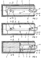
- a housing 6 which has an inflow opening 19 and an outflow opening 20.
- Guide rails 4 with grooves 1 are inserted laterally into the housing.
- two plates 2, 5 and a central plate 3 are provided.
- the plates 2, 5 are guided with corresponding shafts 9, 8 in the grooves 1 of the guide rails 4.
- One or more grooves or groove sections and a corresponding number of shafts can be provided.
- the center plate 3 has two axes 7 which reach through corresponding grooves 12, 13 in the plates 5, 2.
- the plates 2, 5 it is also possible to provide only one axis 7, or there are more than two axes.
- FIGS. 2-4 show three different longitudinal sections through the valve according to the invention.
- valve rod 10 to the central plate 3, which serves to open and close the valve.
- the actuation of the valve rod 10 and its sealing against the housing 6 are not shown in detail.
- FIGS. 2-4 clearly show the link guides, which are designed in the form of grooves 12, 13 on the respective plates 5, 2.
- the plates 5, 2 are secured with shafts 8, 9 in the groove 1 of the guide rail 4 against displacement in the direction of the arrow 15, 16 as long as they are at a certain distance from the central plate (FIG. 4).
- the valve is now opened as follows: The valve rod 10 is moved in the direction of arrow 16.
- the plates 5, 2 are guided with the aid of the shafts 8, 9 in the grooves 1 of the guide rails 4 and can therefore not yet slip in the direction of the arrow 15, 16.
- the movement of the arrow 16 in the directions 17, 18 is implemented via the axes 7 of the middle plate, which engage in the grooves 12, 13.
- the shafts 8, 9 enter the elongated section of the groove 1 of the guide rails 4, so that the plates 2, 5 together with the central plate 3 in the direction of the arrow 15 , 16 are displaceable (Fig. 4).
- the center plate 3 is held in the middle by the grooves 12, 13 on the plates 5, 2, since these grooves 12, 13 are of approximately opposite configuration and therefore bring about an automatic centering of the center plate 3.
- valve rod 10 is pushed in in the direction of the arrow 15, the shafts 8, 9 engaging the vertically running part of the groove 1 and thus preventing further movement of the plates 2, 5 in the direction 15. If the middle plate is moved further in this direction, the kinematic process described above is reversed and the plates 2, 5 are pressed outward in the direction of the arrows 17, 18.
- the elongated area of the groove 1 is made somewhat larger than the outer diameter of the shafts 8, 9 or that which is attached to them Camp 11.
- Bearings 11 are located at the contact points of the shafts 8, 9 and the axes 7 with the corresponding grooves 1 for the shafts 8, 9 and the grooves 12, 13 for the axes 7 provided, which are attached in a suitable manner to the shafts 8, 9 or to the axes 7.
- the present invention encompasses all suitable bearing locks, for example pressing on, securing with the aid of circlips or by changing the diameter of the shaft or the axis. For reasons of clarity, these bearings have not been shown in FIGS. 1-4.
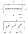
- FIG. 5 shows such a bearing 11, which is fastened on the shaft 8 and can run up and down in the groove 1 of the guide rail 4 in the direction of the arrow 17, 18 and is movable in the direction 15, 16. It is provided that the bearings 11 are supported with the necessary clearance with their outer circumference directly on the respective groove 1, 12, 13.
- the grooves 12, 13, which together with the axes 7 ensure the opening and closing of the valve, can be designed as desired. They do not have to run in a straight line, but can have one or more kinks or an arc shape. Several design options for such groove shapes are shown in FIG. 11, the illustration being made in a plate for the sake of clarity.
- the opening and closing characteristics of the valve can be determined by the shape of these grooves 12, 13. In particular, it is possible to adapt the valve to different, very different boundary conditions. It is only necessary to change the grooves 13, 12 provided in the plates 2, 5. All essential components of the valve can remain unchanged, which enables quick and cheap adaptation to various boundary conditions.
- the grooves 12, 13 can also be designed so that at certain positions of the plates 2, 5, a self-locking of the valve occurs, so that another It is no longer necessary to monitor the valve. This can be done, for example, via grids or corresponding pitch angles.
- valve rod 10 there are of course other valve mechanisms, e.g. hydraulic, pneumatic, magnetic or electrical, possible.
- actuation of the valve can also be achieved by actuating elements (not shown in more detail) which are fitted inside the housing 6.
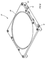
- FIGS. 6-10 a second embodiment of the valve according to the invention is shown.
- the same reference numerals are used for the same components as in FIGS. 1-5.
- only one plate 21 is provided, which is actuated by a central plate 3 with a valve rod 10 in analogy to the first embodiment.
- the center plate 3 engages with the axes 25 in the grooves 12 provided in the plate 21 and is supported with the ends of the axes 25 on the left and right in respective grooves 23, 24 of guide rails 22.
- the plate 21 has one or more shafts 26 on each side, which preferably engage in the grooves 23, 24 like the axes 25 or are provided for the additional grooves.
- the shafts 26 are held in receptacles 27 of the plate 21 (FIG. 8).
- the plate 21 On its upper side, the plate 21 has an annular groove 28 for receiving an O-ring 14.
- the opening and closing of the second embodiment takes place in analogy to the first embodiment by moving the middle plate 3 through the valve rod 10 in the direction of the arrow 15, 16.
- What has been said above with regard to the type and design of the grooves in the plates and guide rails and the corresponding bearings or coatings applies accordingly to the second embodiment.
- the shaft 26 When closing the valve, so when the middle plate 3 and plate 21 are moved, the shaft 26 enters this area 29 and prevents further movement of the plate 21 in the direction 15.
- the shaft 26 acts as a holding device, as in the first embodiment, until the plate 21 is at a certain distance is lowered to the center plate 3, and only then releases the plate 21 for displacement in the direction of arrow 16.
Landscapes
- Engineering & Computer Science (AREA)
- General Engineering & Computer Science (AREA)
- Mechanical Engineering (AREA)
- Sliding Valves (AREA)
- Mechanically-Actuated Valves (AREA)
- Details Of Valves (AREA)
- Preventing Unauthorised Actuation Of Valves (AREA)
- Chair Legs, Seat Parts, And Backrests (AREA)
- Pens And Brushes (AREA)
- External Artificial Organs (AREA)
- Lift Valve (AREA)
Applications Claiming Priority (2)
| Application Number | Priority Date | Filing Date | Title |
|---|---|---|---|
| DE4341816A DE4341816A1 (de) | 1993-12-08 | 1993-12-08 | Ventilmechanik mit Zwangsführung |
| DE4341816 | 1993-12-08 |
Publications (2)
| Publication Number | Publication Date |
|---|---|
| EP0662575A1 true EP0662575A1 (fr) | 1995-07-12 |
| EP0662575B1 EP0662575B1 (fr) | 1999-11-03 |
Family
ID=6504470
Family Applications (1)
| Application Number | Title | Priority Date | Filing Date |
|---|---|---|---|
| EP94119299A Expired - Lifetime EP0662575B1 (fr) | 1993-12-08 | 1994-12-07 | Mécanisme de vanne avec guidage forcé |
Country Status (7)
| Country | Link |
|---|---|
| US (1) | US5743296A (fr) |
| EP (1) | EP0662575B1 (fr) |
| JP (1) | JP3538788B2 (fr) |
| KR (1) | KR100434812B1 (fr) |
| AT (1) | ATE186383T1 (fr) |
| CA (1) | CA2137478C (fr) |
| DE (2) | DE4341816A1 (fr) |
Families Citing this family (4)
| Publication number | Priority date | Publication date | Assignee | Title |
|---|---|---|---|---|
| DE102005043595A1 (de) | 2005-09-12 | 2007-04-19 | Bösch, Hubert | Ventilmechanik für ein Vakuumventil |
| DE102007059039A1 (de) * | 2007-12-06 | 2009-06-18 | Vat Holding Ag | Vakuumventil |
| JP5963091B2 (ja) * | 2013-07-10 | 2016-08-03 | Smc株式会社 | 無摺動型ゲートバルブ |
| US11598429B2 (en) * | 2021-01-18 | 2023-03-07 | Chad Heffernan | Eclipse valve assembly |
Citations (9)
| Publication number | Priority date | Publication date | Assignee | Title |
|---|---|---|---|---|
| DE670C (de) * | 1877-08-25 | N. salmon & A. delaviere in Paris | Neuerungen an Manschetten- und Hemdenknöpfen | |
| DE45641C (de) * | M. EMERY in Marseille | Abschlufsschieber mit Schraubgetriebe und beim Abschliefsen rechtwinklig zur Sitzfläche bewegter Ventilscheibe | ||
| DE636317C (de) * | 1930-10-27 | 1936-10-06 | Dango & Dienenthal Kg | Absperrschieber mit parallelen Dichtflaechen |
| DE929920C (de) * | 1943-02-27 | 1955-07-07 | Manfred Von Ardenne | Vakuumschieberventil |
| DE1190755B (de) * | 1960-06-29 | 1965-04-08 | Commissariat Energie Atomique | Absperrschieber |
| CH402537A (de) * | 1961-02-16 | 1965-11-15 | Licentia Gmbh | Schieberventil |
| DE1957309A1 (de) * | 1968-11-18 | 1970-05-27 | Thebado Eugene A | Ventil fuer Vakuumleitungen |
| DE2601120A1 (de) * | 1976-01-14 | 1977-07-28 | Bergwerksverband Gmbh | Zugschieber zum absperren von gasen in rohrleitungen |
| EP0277323A1 (fr) * | 1986-12-18 | 1988-08-10 | Cetec AG | Vanne à tiroir |
Family Cites Families (10)
| Publication number | Priority date | Publication date | Assignee | Title |
|---|---|---|---|---|
| GB189412715A (en) * | 1894-06-30 | 1895-01-26 | George Elliott | Improvements in or relating to Water Gauges for Use on Steam Boilers. |
| US1156049A (en) * | 1915-01-02 | 1915-10-12 | Gustave P Bopp | Valve. |
| US3397862A (en) * | 1965-12-16 | 1968-08-20 | Atomic Energy Commission Usa | Wedge gate vacuum valve mechanism with coated seat seal |
| CH640924A5 (en) * | 1979-08-28 | 1984-01-31 | Balzers Hochvakuum | Vacuum slide valve |
| IT1153415B (it) * | 1982-01-18 | 1987-01-14 | Giorgio Bormioli | Dispositivo di azionamento in sequenza per organi controllati |
| US4495966A (en) * | 1982-05-24 | 1985-01-29 | Electron Beam Corporation | Separable high vacuum valve |
| DE3224387A1 (de) * | 1982-06-30 | 1984-01-12 | Schertler, Siegfried, 9469 Haag | Vakuumschieberventil |
| DE3440070C2 (de) * | 1984-11-02 | 1993-12-02 | Fichtel & Sachs Ag | Mehrgangnabe für Fahrräder oder dergleichen |
| FR2673991B1 (fr) * | 1991-03-15 | 1993-07-09 | Europ Propulsion | Vanne redondee a la fermeture. |
| US5332002A (en) * | 1993-09-21 | 1994-07-26 | Dril-Quip, Inc. | Gate valve |
-
1993
- 1993-12-08 DE DE4341816A patent/DE4341816A1/de not_active Withdrawn
-
1994
- 1994-12-07 DE DE59408886T patent/DE59408886D1/de not_active Expired - Lifetime
- 1994-12-07 EP EP94119299A patent/EP0662575B1/fr not_active Expired - Lifetime
- 1994-12-07 AT AT94119299T patent/ATE186383T1/de active
- 1994-12-07 CA CA002137478A patent/CA2137478C/fr not_active Expired - Fee Related
- 1994-12-07 US US08/350,780 patent/US5743296A/en not_active Expired - Lifetime
- 1994-12-08 JP JP30485094A patent/JP3538788B2/ja not_active Expired - Fee Related
- 1994-12-08 KR KR1019940033648A patent/KR100434812B1/ko not_active IP Right Cessation
Patent Citations (9)
| Publication number | Priority date | Publication date | Assignee | Title |
|---|---|---|---|---|
| DE45641C (de) * | M. EMERY in Marseille | Abschlufsschieber mit Schraubgetriebe und beim Abschliefsen rechtwinklig zur Sitzfläche bewegter Ventilscheibe | ||
| DE670C (de) * | 1877-08-25 | N. salmon & A. delaviere in Paris | Neuerungen an Manschetten- und Hemdenknöpfen | |
| DE636317C (de) * | 1930-10-27 | 1936-10-06 | Dango & Dienenthal Kg | Absperrschieber mit parallelen Dichtflaechen |
| DE929920C (de) * | 1943-02-27 | 1955-07-07 | Manfred Von Ardenne | Vakuumschieberventil |
| DE1190755B (de) * | 1960-06-29 | 1965-04-08 | Commissariat Energie Atomique | Absperrschieber |
| CH402537A (de) * | 1961-02-16 | 1965-11-15 | Licentia Gmbh | Schieberventil |
| DE1957309A1 (de) * | 1968-11-18 | 1970-05-27 | Thebado Eugene A | Ventil fuer Vakuumleitungen |
| DE2601120A1 (de) * | 1976-01-14 | 1977-07-28 | Bergwerksverband Gmbh | Zugschieber zum absperren von gasen in rohrleitungen |
| EP0277323A1 (fr) * | 1986-12-18 | 1988-08-10 | Cetec AG | Vanne à tiroir |
Also Published As
| Publication number | Publication date |
|---|---|
| JP3538788B2 (ja) | 2004-06-14 |
| CA2137478A1 (fr) | 1995-06-09 |
| ATE186383T1 (de) | 1999-11-15 |
| KR100434812B1 (ko) | 2004-09-20 |
| JPH07198060A (ja) | 1995-08-01 |
| EP0662575B1 (fr) | 1999-11-03 |
| US5743296A (en) | 1998-04-28 |
| KR950019326A (ko) | 1995-07-22 |
| DE4341816A1 (de) | 1995-06-14 |
| CA2137478C (fr) | 2005-07-05 |
| DE59408886D1 (de) | 1999-12-09 |
Similar Documents
| Publication | Publication Date | Title |
|---|---|---|
| EP1291563B1 (fr) | Soupape non-retour et vanne avec une telle soupape non-retour | |
| CH674558A5 (fr) | ||
| DE102010035622B4 (de) | Abgasrückführventil für eine Verbrennungskraftmaschine | |
| DE2626236A1 (de) | Ventilaufbau | |
| EP0476265B1 (fr) | Vérin à fluide avec cylindre fendu | |
| DD224381A5 (de) | Absperrschieber | |
| EP2855985B1 (fr) | Vanne d'arrêt | |
| EP0662575A1 (fr) | Mécanisme de vanne avec guidage forcé | |
| DE19934383C2 (de) | Dämpfungseinrichtung und Ventileinsatz für eine solche Dämpfungseinrichtung | |
| EP0568858B1 (fr) | Dispositif de verrouillage d'un piston commandé par pression, en particulier pour la commande d'une barre antirenversement d'un véhicule | |
| EP0277323B1 (fr) | Vanne à tiroir | |
| DE202010001548U1 (de) | Spindel-Mutter-Getriebe und Lineareinheit mit einem solchen Getriebe | |
| DE202022102340U1 (de) | Ventilsitz, Hubventilglied und Hubventil | |
| DE3018920A1 (de) | Verriegelung fuer druckzylinderkolben | |
| DE2637217A1 (de) | Absperrschieber mit zweiteiliger schieberzunge | |
| DE2627607A1 (de) | Absperrventil | |
| DE69610009T2 (de) | Steuervorrichtung mit Elektromagnet mit Kern ohne Reibung und Verwendung bei Ventilen mit Kontinusteuerung | |
| DE3643069C2 (fr) | ||
| DE102020114807A1 (de) | Möbel | |
| DE19615814A1 (de) | Teleskopierbares Staubsaugerrohr | |
| EP1160493A1 (fr) | Robinet | |
| DE2736708A1 (de) | Zweiplatten-schieber | |
| DE10317190A1 (de) | Schwingungsdämpfer mit hydraulischem Zuganschlag | |
| EP1304522A2 (fr) | Raccord d'aération avec compensation des forces au niveau de la douille de manoeuvre | |
| DE102006024881A1 (de) | Führungseinheit für Linearführungen in Fahrzeugen, vorzugsweise in Kraftfahrzeugen |
Legal Events
| Date | Code | Title | Description |
|---|---|---|---|
| PUAI | Public reference made under article 153(3) epc to a published international application that has entered the european phase |
Free format text: ORIGINAL CODE: 0009012 |
|
| AK | Designated contracting states |
Kind code of ref document: A1 Designated state(s): AT CH DE FR GB IT LI |
|
| 17P | Request for examination filed |
Effective date: 19960112 |
|
| 17Q | First examination report despatched |
Effective date: 19971023 |
|
| GRAG | Despatch of communication of intention to grant |
Free format text: ORIGINAL CODE: EPIDOS AGRA |
|
| GRAG | Despatch of communication of intention to grant |
Free format text: ORIGINAL CODE: EPIDOS AGRA |
|
| GRAH | Despatch of communication of intention to grant a patent |
Free format text: ORIGINAL CODE: EPIDOS IGRA |
|
| GRAH | Despatch of communication of intention to grant a patent |
Free format text: ORIGINAL CODE: EPIDOS IGRA |
|
| GRAA | (expected) grant |
Free format text: ORIGINAL CODE: 0009210 |
|
| AK | Designated contracting states |
Kind code of ref document: B1 Designated state(s): AT CH DE FR GB IT LI |
|
| REF | Corresponds to: |
Ref document number: 186383 Country of ref document: AT Date of ref document: 19991115 Kind code of ref document: T |
|
| REG | Reference to a national code |
Ref country code: CH Ref legal event code: EP |
|
| REF | Corresponds to: |
Ref document number: 59408886 Country of ref document: DE Date of ref document: 19991209 |
|
| REG | Reference to a national code |
Ref country code: CH Ref legal event code: NV Representative=s name: PATENTANWALTSBUERO JEAN HUNZIKER |
|
| ITF | It: translation for a ep patent filed | ||
| ET | Fr: translation filed | ||
| GBT | Gb: translation of ep patent filed (gb section 77(6)(a)/1977) |
Effective date: 20000127 |
|
| PLBE | No opposition filed within time limit |
Free format text: ORIGINAL CODE: 0009261 |
|
| STAA | Information on the status of an ep patent application or granted ep patent |
Free format text: STATUS: NO OPPOSITION FILED WITHIN TIME LIMIT |
|
| 26N | No opposition filed | ||
| REG | Reference to a national code |
Ref country code: GB Ref legal event code: IF02 |
|
| PGFP | Annual fee paid to national office [announced via postgrant information from national office to epo] |
Ref country code: IT Payment date: 20111229 Year of fee payment: 18 |
|
| REG | Reference to a national code |
Ref country code: DE Ref legal event code: R082 Ref document number: 59408886 Country of ref document: DE Representative=s name: PETER RIEBLING, DE |
|
| REG | Reference to a national code |
Ref country code: CH Ref legal event code: PUE Owner name: VG SCIENTA LTD. Free format text: BOESCH, HUBERT#SANDSTRASSE 29#6890 LUSTENAU (AT) -TRANSFER TO- VG SCIENTA LTD.#MAUNSELL ROAD#HASTINGS, EAST SUSSEX TN 38 9NN (GB) |
|
| REG | Reference to a national code |
Ref country code: GB Ref legal event code: 732E Free format text: REGISTERED BETWEEN 20121025 AND 20121031 |
|
| REG | Reference to a national code |
Ref country code: FR Ref legal event code: TP Owner name: VG SCIENTA LIMITED, GB Effective date: 20121105 |
|
| REG | Reference to a national code |
Ref country code: DE Ref legal event code: R082 Ref document number: 59408886 Country of ref document: DE Representative=s name: RIEBLING, PETER, DIPL.-ING. DR.-ING., DE Effective date: 20121029 Ref country code: DE Ref legal event code: R081 Ref document number: 59408886 Country of ref document: DE Owner name: VG SCIENTA LTD., HASTINGS, GB Free format text: FORMER OWNER: BOESCH, HUBERT, LUSTENAU, AT Effective date: 20121029 Ref country code: DE Ref legal event code: R081 Ref document number: 59408886 Country of ref document: DE Owner name: VG SCIENTA LTD., GB Free format text: FORMER OWNER: BOESCH, HUBERT, LUSTENAU, AT Effective date: 20121029 |
|
| REG | Reference to a national code |
Ref country code: FR Ref legal event code: CA Effective date: 20121120 |
|
| REG | Reference to a national code |
Ref country code: AT Ref legal event code: PC Ref document number: 186383 Country of ref document: AT Kind code of ref document: T Owner name: VG SCIENTA LTD, GB Effective date: 20130128 |
|
| PGFP | Annual fee paid to national office [announced via postgrant information from national office to epo] |
Ref country code: AT Payment date: 20120412 Year of fee payment: 18 |
|
| REG | Reference to a national code |
Ref country code: AT Ref legal event code: MM01 Ref document number: 186383 Country of ref document: AT Kind code of ref document: T Effective date: 20121207 |
|
| PG25 | Lapsed in a contracting state [announced via postgrant information from national office to epo] |
Ref country code: AT Free format text: LAPSE BECAUSE OF NON-PAYMENT OF DUE FEES Effective date: 20121207 |
|
| PG25 | Lapsed in a contracting state [announced via postgrant information from national office to epo] |
Ref country code: IT Free format text: LAPSE BECAUSE OF NON-PAYMENT OF DUE FEES Effective date: 20121207 |
|
| PGFP | Annual fee paid to national office [announced via postgrant information from national office to epo] |
Ref country code: DE Payment date: 20131210 Year of fee payment: 20 Ref country code: CH Payment date: 20131227 Year of fee payment: 20 Ref country code: GB Payment date: 20131219 Year of fee payment: 20 |
|
| PGFP | Annual fee paid to national office [announced via postgrant information from national office to epo] |
Ref country code: FR Payment date: 20131231 Year of fee payment: 20 |
|
| REG | Reference to a national code |
Ref country code: DE Ref legal event code: R071 Ref document number: 59408886 Country of ref document: DE |
|
| REG | Reference to a national code |
Ref country code: CH Ref legal event code: PL |
|
| REG | Reference to a national code |
Ref country code: GB Ref legal event code: PE20 Expiry date: 20141206 |
|
| PG25 | Lapsed in a contracting state [announced via postgrant information from national office to epo] |
Ref country code: GB Free format text: LAPSE BECAUSE OF EXPIRATION OF PROTECTION Effective date: 20141206 |