EP0476265B1 - Vérin à fluide avec cylindre fendu - Google Patents
Vérin à fluide avec cylindre fendu Download PDFInfo
- Publication number
- EP0476265B1 EP0476265B1 EP91112327A EP91112327A EP0476265B1 EP 0476265 B1 EP0476265 B1 EP 0476265B1 EP 91112327 A EP91112327 A EP 91112327A EP 91112327 A EP91112327 A EP 91112327A EP 0476265 B1 EP0476265 B1 EP 0476265B1
- Authority
- EP
- European Patent Office
- Prior art keywords
- guide
- slot
- cylinder
- output member
- power output
- Prior art date
- Legal status (The legal status is an assumption and is not a legal conclusion. Google has not performed a legal analysis and makes no representation as to the accuracy of the status listed.)
- Expired - Lifetime
Links
Images

Classifications
-
- F—MECHANICAL ENGINEERING; LIGHTING; HEATING; WEAPONS; BLASTING
- F15—FLUID-PRESSURE ACTUATORS; HYDRAULICS OR PNEUMATICS IN GENERAL
- F15B—SYSTEMS ACTING BY MEANS OF FLUIDS IN GENERAL; FLUID-PRESSURE ACTUATORS, e.g. SERVOMOTORS; DETAILS OF FLUID-PRESSURE SYSTEMS, NOT OTHERWISE PROVIDED FOR
- F15B15/00—Fluid-actuated devices for displacing a member from one position to another; Gearing associated therewith
- F15B15/08—Characterised by the construction of the motor unit
- F15B15/082—Characterised by the construction of the motor unit the motor being of the slotted cylinder type
Definitions
- the invention relates to a pressure medium cylinder with a longitudinally slotted cylinder tube which is closed at the end and which is delimited on the slot side by an outer surface perpendicular to the slot and in which a piston is guided displaceably and sealed by means of two piston seals arranged near its ends, which in the area between the piston seals by means of one of the slots penetrating connecting means is firmly connected to a driver located in front of the slot on the outside of the cylinder tube, with a sealing tape arranged inside the inside of the cylinder tube and sealing the sealing outside of the section enclosed by the two piston seals, and optionally a sealing tape covering the outside of the slot with the exception of the passage area of the connecting means, with an the outside of the slot axially displaceably guided force output member, which at least faces away from the driver and overlaps laterally, where in the case of the guide of the power output member, which is symmetrical to a central plane running through the slot and contains the cylinder axis, on each side of the slot has two plane guide tracks running
- Such a pressure medium cylinder is known from EP-B 0 157 892, in which the guide is obviously designed in accordance with DE-A 31 24 915 or EP-B 0 068 088 corresponding to this document.
- the force-transmitting member at least partially overlaps the side surfaces of the cylinder tube in an area in which wedge-like guide grooves are incorporated into these side surfaces.
- the power output member carries guide strips which engage the keyways with correspondingly roof-like guide surfaces. The guide strips can be adjusted perpendicular to the central plane by means of adjusting screws arranged at right angles to the central plane in the power output member.
- a cylinder arrangement is known in which a slide can be displaced along first and second guide rails.
- the play between the second, inclined guide rails and the guide parts is adjustable.
- the guide of the force-transmitting member on both sides of the slot within the guide groove has one guide track and the other guide track on the outer surface, one guide track being non-adjustable and inclined to The central plane runs, and the other guideway runs parallel to the outer surface and has the guide strip which is adjustable in the direction perpendicular to the outer surface.
- the guide strips In the known pressure cylinder, as already mentioned above, the guide strips must be guided so that they can move transversely to the central plane in the force-transmitting member in order to be able to adjust them by means of the adjusting screws.
- the transversely displaceable guidance of the guide strips requires play between them and the force output member, which cannot be adjusted by means of the adjusting screws.
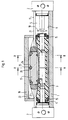
- the pressure medium cylinder has a cylinder tube 1, which is closed at the end by cylinder cover 2.
- the cylinder covers 2 convey the pressure medium feeds to the pressurization chambers 4 and 5 located on both sides of a piston 3.
- the cylinder tube 1 has an approximately square cross-section on the outside, it is provided with an eccentrically arranged cylinder bore 6, in which the piston 3 is guided.
- a plurality of mounting and guide grooves 7, which are of no further interest here, are incorporated.
- the cylinder wall 8 of the cylinder tube 1 lying in the direction of offset of the cylinder bore 6 is cut open by means of a slot 10 running parallel to the cylinder axis 9.
- the cylinder tube 1 has an outer surface 11 on the side of the slot 10 and a side surface 12 or 13 on the side of the slot 10.
- a central plane 14 runs through the cylinder axis 9 and centrally through the slot 10.
- the piston 3 is axially relatively elongated, it has a piston seal 15 near each of its two ends to limit the pressurizing spaces 4 and 5, respectively.
- the piston 3 is provided with a web-like connecting means 16 which projects through the slot 10 and firmly connects the piston 3 to a driver 17 located in front of the slot 10 on the outside of the cylinder tube.
- the driver 17 is facing away from the slot and overlapped laterally by a bow-like force output member 18 which is guided on both sides of the slot 10 by means of guide arrangements to be described later in detail on the cylinder tube 1.
- the slot 10 is covered on the inside of the cylinder tube in the area of the pressurized spaces 4 and 5 by a sealing tape 19 in a pressure-tight manner; in the area of the piston 3 between its piston seals 15, the sealing tape 19 is lifted from the slot 10 and guided through a guide channel 20 of the piston 3, such that the slot 10 is free for the connection means 16 to pass through.
- the slot 10 is covered outside the area of the piston 3 by a shroud 21, which is also lifted from the slot 10 in the area of the piston 3 and is guided through a space 22 located between the driver 17 and the force output member 18, such that the connecting means 16 can pass through the slot 10 and is firmly connected to the driver 17, can optionally be made in one piece with this.
- the tape holder can also be made in another known manner.
- the driver 17 For coupling the driver 17 to the force output member 18, the driver 17 has a transverse groove 24 approximately in the middle of its longitudinal extension on its side facing away from the slot, to each of which a groove-like recess 25 in the force output member 18 adjoins the transverse groove 24.
- a feather key 26 is inserted in such a way that its end portions in the recesses 25 engage; the feather key 26 thus extends transversely to the central plane 14.
- the feather key 26 together with the transverse groove 24 and the recesses 25 represents a coupling device between the driver 17 and the force output member 18, which, depending on the play of the feather key 26 in the transverse groove 24 or the recesses 25 relative movements and rotations between the driver 17 and the power output member 18 allows.
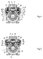
- a guide groove 27 and 28 each emanate from the outer surface 11 to the side of the slot 10, which are incorporated in the cylinder tube 1 and which are inclined obliquely downward from the outer surface 11 toward the side surfaces 12 and 13, So run to the middle level 14 diverging.
- the correspondingly inclined walls of the guide grooves 27 and 28 on the outer surface side represent guide surfaces 29 and 30, respectively, against which corresponding guide surfaces of the force output member 18 are slidably applied; the guide surfaces of the force output member 18 are located on guide strips 31 and 32, which are firmly held on strip-like projections 33 of the power output member 18 which project obliquely downwards and outwards.
- the extensions 33 engage in the guide grooves 27, 28 with play on all sides.
- each of the extensions 33 is followed by a section 34 of the force output member 18, the sections 34 cover the outer surface 11 until their transition into the side surfaces 12 and 13.
- a guide strip 35 or 36 is vertically displaceable in the sections 34, So slidably inserted parallel to the central plane 14.
- the guide strips 35 and 36 like the guide strips 31 and 32, extend parallel to the cylinder axis 9.
- the undersides of the guide strips 35 and 36 lie displaceably on flat edge strip sections of the outer surface 11.
- Set screws 37, 38 are adjustably screwed to the two sections 34, the set screws 37 and 38 have axial directions which run parallel to the central plane 14 and cross the cylinder axis 9 at right angles.
- a plurality of adjusting screws 37 and 38 are arranged at uniform intervals in each section 34 over the longitudinal extent of the force output member 18 in the direction of the cylinder axis 9.
- the screwing of the set screws 37 and 38 to the sections 34 can be designed to be self-locking, but lock nuts can also be provided in a manner not shown for securing the respective adjustment position.
- the ends of the set screws 37 and 38 on the outer surface lie on support strips 39 on the sides of the guide strips 35 and 36 facing away from the outer surface; the support strips 39 extend parallel to the cylinder axis 9 and, together with the guide strips 35 and 36, are displaceably guided parallel to the central plane 14.
- the guide strips 35 and 36 thus form, together with the outer surface 11, adjustable guide tracks 11, 35 and 11, 36, respectively, which lie in a plane perpendicular to the central plane 14.
- the height of the guide strips 35 and 36 can be adjusted such that the guide tracks 29, 31; 30.32; 11, 35 and 11, 36 a desired play possibility or sliding mobility remains, the force output member 18 is thus adjusted in the desired manner relative to the cylinder tube 1 and guided displaceably.
- the guideways 29, 31 and 30, 32 take over the lateral guidance of the force output member 18 and preclude its lifting up from the cylinder tube 1.
- Possible side play of the guide rails 35 and 36 relative to the sections 34 have no influence on the quality of the lateral guidance of the power output member 18 relative to the cylinder tube 1.
- the force output member 18 overlaps the upper portions of the side surfaces 12 and 13 of the cylinder tube 1 with guide legs 40 on the side of the guide tracks 11, 35 and 11, 36.
- guide grooves 41 and 42 extend from the side surfaces 12 and 13 , which is inclined substantially obliquely in the direction of the outer surface 11 Extend cylinder tube 1.
- the outer surface walls of these guide grooves 41 and 42 form guide surfaces 43 and 44, respectively, which correspond to the guide surfaces 29 and 30 of the exemplary embodiment according to FIGS. 2 and 3 and against which the guide strips 31 and 32 rest, which are firmly attached to the guide grooves 41 and 42 engaging portions of the guide leg 40 are connected.
- the embodiment according to FIG. 5 corresponds with regard to the position and arrangement of the guideways 11, 35; 11.36; 31, 43 and 32, 34 completely the exemplary embodiment according to FIG. 4, it thus also has the functions and advantages explained for the first described exemplary embodiment.
- the exemplary embodiment according to FIG. 5 differs from that according to FIG. 4 only with regard to the adjustment arrangement.
- the set screws 37 and 38 are screwed to the guide legs 40 with an axial direction perpendicular to the center plane 14.
- the set screws 37 and 38 act on wedge members 45 which are displaceable in the force output member 18 and which are displaceably supported on the outer surface facing away from the force output member 18 by means of wedge surfaces 46 and on the outer surface facing the guide rails 35, 36, optionally with interposed rails corresponding to the support rails 39, not shown.
- the wedge surfaces 46 extend in the direction of distance from the center plane 14 to the outer surface 11 so that when the set screws 37, 38 are screwed in together with the guide strips 35, 36 there is a displacement within the force output member 14 in the direction of the outer surface 11 Experienced.
- the set screws 37, 38 can be designed to be self-locking or lockable with lock nuts.
- a wedge adjustment according to Figure 5 can also be provided in the embodiment of Figures 2 and 3.
- the guide grooves 41, 42 can also be designed in a T-groove-like manner on their side facing away from the outer surface 11, as they are then also used to hold parts to be fastened to the cylinder tube 1, for example end stops suitable for the power output member 14.
- end stops suitable for the power output member 14.
- cover band 21 it may be expedient to design the cover band 21 with a width that is greater than the distance between the mutually facing mouth edges of the two guide grooves 27 and 28; the space 22 and thus the entire force output member 18 are then designed to be correspondingly wide in order to carry out the shroud 21 through the force take-off member 18.
- This modification ensures that the cover band 21 not only covers the slot 10, but also the two guide grooves 27 and 28 outside the force output member 18 and thus protects it from dirt.
- a pressure medium cylinder is particularly well suited for operation in an environment where there is a risk of contamination.
- the guide strips 35, 36 do not have to interact directly with the outer surface 11, which extends over the entire width of the cylinder tube, to form the guideways 11, 35 and 11, 36; rather, they can also rest on outer surface sections that are vertically offset from the rest of the outer surface 11; the vertical offset facilitates the processing of the surface sections of the cylinder tube 1 which cooperate with the guide strips 35, 36.
- the guide strips 31, 32, 35 and / or 36 can be mounted from an end face of the force output element 18, even if the force output element 18 is already on the cylinder tube 1. This makes it easy to replace worn guide rails.
- a piston (3) is only coupled to a force output member (18) for axial force transmission.
- the force output member (18) has a guide on the cylinder tube (1), which is designed as a mirror image of a central plane (14) through the cylinder axis (9) and the slot of the cylinder tube (1).
- the guide On both sides of the central plane (14), the guide has two guideways (11, 35 and 29, 31 or 11, 36 and 30, 32).
- One guideway (29, 31 or 30, 32) runs inclined to the central plane (14) within an oblique guide groove (27 or 28) in the cylinder tube (1) and is not adjustable, while the other guideway (11, 35 or 11, 36) runs in or parallel to the outer surface (11) which has the slot and is perpendicular to the central plane (14) and can be adjusted perpendicularly to this outer surface (11).
- a guide bar (35 or 36) adjustable by means of set screws (37 or 38) perpendicular to the outer surface (11) is provided in the force output member (18).
Claims (8)
- Vérin à fluide sous pression comportant un cylindre (1) fendu longitudinalement, qui est fermé à ses extrémités, qui est délimité, du côté de la fente (10), par une surface extérieure (11) perpendiculaire à cette fente, et dans lequel un piston (3) coulisse avec étanchéité grâce à la présence de deux garnitures d'étanchéité de piston (15), disposées à proximité des extrémités du piston, ce piston étant relié de façon fixe, dans la zone située entre les garnitures d'étanchéité de piston (15), au moyen d'un moyen de liaison (16) s'engageant dans la fente (10), à un organe d'entraînement (17) se trouvant sur la face extérieure du cylindre devant la fente (10), une bande d'étanchéité (19), qui est disposée sur le côté intérieur du cylindre et qui recouvre, d'une manière étanche au fluide sous pression, la fente (10) à l'extérieur de la section enfermée par les deux garnitures d'étanchéité de piston (15), et éventuellement une bande de revêtement (21), qui recouvre, sur le côté extérieur, la fente (10) à l'exception de la zone de pénétration du moyen de liaison (16), un organe de prélèvement de force (18), qui est guidé de manière à être déplaçable axialement sur la face extérieure du cylindre et qui entoure l'organe d'entraînement (17) au moins à l'opposé de la fente et latéralement, et dans lequel le guide, qui est formé symétriquement par rapport à un plan médian (14) passant par la fente (10) et contenant l'axe (9) du cylindre, de l'organe de prélèvement de force (18), possède, des deux côtés de la fente (10), deux pistes planes respectives de guidage (29, 31 ou 41, 43 et 11, 35 ainsi que 30, 32 ou 32, 44 et 11, 36), qui font un angle entre elles et qui sont parallèles à l'axe et comportant respectivement une rainure de guidage (27, 28 ou 41, 42) ménagée dans le cylindre (1) et une barrette de guidage (35, 36) disposée de manière à être ajustable sur l'organe de prélèvement de force (18), et un dispositif d'accouplement, qui est disposé entre l'organe d'entraînement (17) et l'organe de prélèvement de force (18) et qui transmet des forces axiales entre ces éléments (17 et 18) tout en ayant une mobilité limitée transversalement et en rotation, caractérisé par le fait que le guide de l'organe de prélèvement de force (18) a, des deux côtés de la fente (10), à l'intérieur de la rainure de guidage (27, 28 ou 41, 42), respectivement une piste de guidage (29, 31; 30, 32 ou 41, 43; 32, 47) et, sur la surface extérieure (11), l'autre piste de guidage (11, 35; 11, 36), une piste de guidage (39, 31; 30, 32 ou 31, 43; 32, 44) n'étant pas ajustable et étant inclinée par rapport au plan médian (14), tandis que l'autre piste de guidage (11, 35; 11, 36) est parallèle à la surface extérieure (11) et possède la barrette de guidage (35; 36) ajustable dans une direction perpendiculaire à la surface extérieure (11).
- Vérin à fluide sous pression suivant la revendication 1, caractérisé en ce que les rainures de guidage (27, 28) s'étendent à partir de la surface extérieure (11) en étant inclinées obliquement en direction des surfaces latérales (12, 13) du cylindre (1), et des premières surfaces de guidage (29, 30) sont situées sur les surfaces obliques, tournées vers la surface extérieure (11), des rainures de guidage (27, 28) (figures 2, 3).
- Vérin à fluide sous pression suivant la revendication 2 comportant une bande de revêtement, caractérisé par le fait que la bande de revêtement a une largeur qui est supérieure à la distance entre des bords mutuellement opposés de l'embouchure des deux rainures de guidage (27, 28), de sorte que cette bande peut recouvrir outre la fente (10), également les embouchures des deux rainures de guidage (27, 28).
- Vérin à fluide sous pression suivant la revendication 1, caractérisé par le fait que les rainures de guidage (41, 42) s'étendent en position oblique, à partir des surfaces latérales (12, 13) du cylindre (1), qui se raccordent à la surface extérieure (11), en direction de cette surface, et des premières surfaces de guidage (43, 44) sont situées sur les surfaces obliques, tournées vers la surface extérieure (11), des rainures de guidage (41, 42). (Figures 4, 5).
- Vérin à fluide sous pression suivant la revendication 4, caractérisé par le fait que les rainures de guidage (41, 42) sont élargies avec une forme de rainure en T, sur le côté tourné à l'opposé de la surface extérieure (11).
- Vérin à fluide sous pression suivant une ou plusieurs des revendications précédentes, caractérisé par le fait que les barrettes de guidage (35, 36), qui sont retenues dans l'organe de prélévement de force (18), peuvent être ajustées au moyen de vis de réglage (37, 38), qui sont disposées dans l'organe de prélèvement de force (18), perpendiculairement à la surface extérieure (11) (figures 2 à 4).
- Vérin à fluide sous pression suivant une ou plusieurs des revendications 2 à 5, caractérisé par le fait que les barrettes de guidage (35, 36) sont disposées dans l'organe de prélèvement de force (18) et sont supportées, perpendiculairement à la surface extérieure (11), par des organes en coin (45) possédant des surfaces en coin (46) qui sont inclinées par rapport à la surface extérieure (11), les organes en coin (45) étant réglables au moyen de vis de réglage (37, 38), qui sont disposées perpendiculairement au plan médian (14), dans l'organe de prélèvement de force (18). (Figure 5).
- Vérin à fluide sous pression suivant la revendication 7, caractérisé par le fait que les surfaces en coin (46) sont inclinées de manière à diverger à partir de la surface extérieure (11), dans une direction s'écartant du plan médian (14).
Applications Claiming Priority (2)
| Application Number | Priority Date | Filing Date | Title |
|---|---|---|---|
| DE4024716A DE4024716A1 (de) | 1990-08-03 | 1990-08-03 | Druckmittelzylinder mit laengsgeschlitztem zylinderrohr |
| DE4024716 | 1990-08-03 |
Publications (2)
| Publication Number | Publication Date |
|---|---|
| EP0476265A1 EP0476265A1 (fr) | 1992-03-25 |
| EP0476265B1 true EP0476265B1 (fr) | 1994-10-12 |
Family
ID=6411618
Family Applications (1)
| Application Number | Title | Priority Date | Filing Date |
|---|---|---|---|
| EP91112327A Expired - Lifetime EP0476265B1 (fr) | 1990-08-03 | 1991-07-23 | Vérin à fluide avec cylindre fendu |
Country Status (4)
| Country | Link |
|---|---|
| EP (1) | EP0476265B1 (fr) |
| JP (1) | JP3332944B2 (fr) |
| AT (1) | ATE112822T1 (fr) |
| DE (2) | DE4024716A1 (fr) |
Families Citing this family (12)
| Publication number | Priority date | Publication date | Assignee | Title |
|---|---|---|---|---|
| JP2512354B2 (ja) * | 1991-10-14 | 1996-07-03 | エスエムシー株式会社 | ロッドレスシリンダ |
| US5275088A (en) * | 1991-10-11 | 1994-01-04 | Smc Kabushiki Kaisha | Rodless cylinder |
| JP2512356B2 (ja) * | 1991-11-01 | 1996-07-03 | エスエムシー株式会社 | ロッドレスシリンダ |
| JP2575245B2 (ja) * | 1991-11-01 | 1997-01-22 | エスエムシー株式会社 | ロッドレスシリンダ |
| EP0542211B1 (fr) * | 1991-11-11 | 1997-04-23 | Smc Kabushiki Kaisha | Vérin sans tige |
| DE69300855T2 (de) * | 1992-07-21 | 1996-11-07 | Smc Kk | Kolbenstangenloser Zylinder. |
| DE4400483C2 (de) * | 1994-01-11 | 1996-12-19 | Invest Tech Ag | Linearantriebszylinder |
| JPH07217607A (ja) * | 1994-02-03 | 1995-08-15 | Smc Corp | 負荷の位置決め装置 |
| AT403502B (de) * | 1994-11-30 | 1998-03-25 | Hygrama Ag | Kolbenstangenloser druckmittelzylinder |
| US6336393B1 (en) | 1998-07-01 | 2002-01-08 | Parker-Hannifin Corporation | Rodless pneumatic cylinder |
| JP4587103B2 (ja) | 2005-04-19 | 2010-11-24 | Smc株式会社 | シリンダ装置のガイド機構 |
| JP7051331B2 (ja) * | 2017-08-23 | 2022-04-11 | 株式会社ヒラノテクシード | シリンダ装置及びそれを用いたウエブの接続装置 |
Family Cites Families (5)
| Publication number | Priority date | Publication date | Assignee | Title |
|---|---|---|---|---|
| DE3124915C2 (de) | 1981-06-25 | 1984-10-31 | Kaiser, Siegmund H., Ing.(grad.), 7440 Nürtingen | Druckmittelzylinder mit einem längsgeschlitzten endseitig verschlossenen Zylinderrohr |
| ATE27990T1 (de) | 1984-04-10 | 1987-07-15 | Reinhard Lipinski | Lineartransportvorrichtung. |
| US4724744A (en) | 1985-12-18 | 1988-02-16 | Tol-O-Matic, Inc. | Carrier bracket for power cylinder |
| JPH0765602B2 (ja) * | 1987-01-30 | 1995-07-19 | 豊和工業株式会社 | ロツドレスシリンダ |
| US4785716A (en) | 1987-02-27 | 1988-11-22 | Tol-O-Matic, Inc. | Pneumatic cylinder and brake mechanism therefor |
-
1990
- 1990-08-03 DE DE4024716A patent/DE4024716A1/de not_active Withdrawn
-
1991
- 1991-07-23 AT AT91112327T patent/ATE112822T1/de not_active IP Right Cessation
- 1991-07-23 DE DE59103220T patent/DE59103220D1/de not_active Expired - Fee Related
- 1991-07-23 EP EP91112327A patent/EP0476265B1/fr not_active Expired - Lifetime
- 1991-07-31 JP JP19141991A patent/JP3332944B2/ja not_active Expired - Fee Related
Also Published As
| Publication number | Publication date |
|---|---|
| ATE112822T1 (de) | 1994-10-15 |
| DE4024716A1 (de) | 1992-02-06 |
| EP0476265A1 (fr) | 1992-03-25 |
| DE59103220D1 (de) | 1994-11-17 |
| JP3332944B2 (ja) | 2002-10-07 |
| JPH05133406A (ja) | 1993-05-28 |
Similar Documents
| Publication | Publication Date | Title |
|---|---|---|
| EP0068088B1 (fr) | Vérin à fluide à cylindre fendu et extrémitées fermées | |
| EP0476265B1 (fr) | Vérin à fluide avec cylindre fendu | |
| DE2702750C3 (de) | Gleitschuh für die Spanneinrichtung einer Gnfcenverbmivorrichtung | |
| DD236370A5 (de) | Kolbenstangenloser zylinder | |
| DE102007058630A1 (de) | Fluiddruckzylinder | |
| EP0684174B1 (fr) | Dispositif de verrouillage pour pièces d'aiguillage de chemin de fer | |
| DE202010003706U1 (de) | Vorrichtung mit mindestens zwei relativ zueinander bewegbaren Teilen | |
| EP1394012B1 (fr) | Dispositif de fixation pour deux elements monté coulissant l'un par rapport à l'autre | |
| EP0141405B1 (fr) | Cylindre à fluide de pression | |
| DE3732561A1 (de) | Verriegelbarer hydraulikzylinder | |
| DE2737936C3 (de) | Justiereinrichtung im Verbindungsweg zwischen einer Schaftmaschine und einem Schaft | |
| DE19530051C2 (de) | Steckkommutator | |
| DE19815474A1 (de) | Lineareinheit mit einer Gleitführung für einen Schlitten | |
| DE3144359A1 (de) | "klemmkopf" | |
| EP0395915B1 (fr) | Cylindre de tavail sans tige de piston | |
| EP0918174A2 (fr) | Actionneur linéaire à entraínement motorisé | |
| EP1574283B1 (fr) | Actionneur linéaire avec une configuration spéciale des butées de fin de course du chariot | |
| EP0388586B2 (fr) | Vérin à fluide sous pression | |
| EP0914562A1 (fr) | Entrainement lineaire sans tige de piston | |
| EP0475032B1 (fr) | Vérin à fluide avec cylindre fendu | |
| EP0232832B1 (fr) | Carcasse d'une carrosserie | |
| DE3145375C2 (de) | Mehrteiliges Rahmenprofil | |
| EP3112577B1 (fr) | Joint abaissable | |
| DE4037863A1 (de) | Absperrarmatur mit querdichtung | |
| DE19817427A1 (de) | Klemmverbinder |
Legal Events
| Date | Code | Title | Description |
|---|---|---|---|
| PUAI | Public reference made under article 153(3) epc to a published international application that has entered the european phase |
Free format text: ORIGINAL CODE: 0009012 |
|
| 17P | Request for examination filed |
Effective date: 19911206 |
|
| AK | Designated contracting states |
Kind code of ref document: A1 Designated state(s): AT CH DE FR GB IT LI NL SE |
|
| 17Q | First examination report despatched |
Effective date: 19940318 |
|
| GRAA | (expected) grant |
Free format text: ORIGINAL CODE: 0009210 |
|
| AK | Designated contracting states |
Kind code of ref document: B1 Designated state(s): AT CH DE FR GB IT LI NL SE |
|
| REF | Corresponds to: |
Ref document number: 112822 Country of ref document: AT Date of ref document: 19941015 Kind code of ref document: T |
|
| REF | Corresponds to: |
Ref document number: 59103220 Country of ref document: DE Date of ref document: 19941117 |
|
| ET | Fr: translation filed | ||
| ITF | It: translation for a ep patent filed |
Owner name: BARZANO' E ZANARDO ROMA S.P.A. |
|
| EAL | Se: european patent in force in sweden |
Ref document number: 91112327.1 |
|
| GBT | Gb: translation of ep patent filed (gb section 77(6)(a)/1977) |
Effective date: 19950118 |
|
| PLBE | No opposition filed within time limit |
Free format text: ORIGINAL CODE: 0009261 |
|
| STAA | Information on the status of an ep patent application or granted ep patent |
Free format text: STATUS: NO OPPOSITION FILED WITHIN TIME LIMIT |
|
| 26N | No opposition filed | ||
| REG | Reference to a national code |
Ref country code: CH Ref legal event code: PUE Owner name: KNORR-BREMSE AG TRANSFER- IMI NORGREN GMBH |
|
| NLS | Nl: assignments of ep-patents |
Owner name: IMI NORGREN GMBH |
|
| REG | Reference to a national code |
Ref country code: FR Ref legal event code: TP Free format text: CORRECTION |
|
| REG | Reference to a national code |
Ref country code: GB Ref legal event code: 732E |
|
| REG | Reference to a national code |
Ref country code: GB Ref legal event code: IF02 |
|
| REG | Reference to a national code |
Ref country code: CH Ref legal event code: PCAR Free format text: ISLER & PEDRAZZINI AG;POSTFACH 1772;8027 ZUERICH (CH) |
|
| REG | Reference to a national code |
Ref country code: CH Ref legal event code: NV Representative=s name: KIRKER & CIE S.A. Ref country code: CH Ref legal event code: PUE Owner name: NORGREN GMBH Free format text: IMI NORGREN GMBH#BRUCKSTRASSE 93#ALPEN (DE) -TRANSFER TO- NORGREN GMBH#BRUCKSTRASSE 93#46519 ALPEN (DE) |
|
| NLS | Nl: assignments of ep-patents |
Owner name: IMI NORGREN HERION GMBH Effective date: 20090120 |
|
| NLT1 | Nl: modifications of names registered in virtue of documents presented to the patent office pursuant to art. 16 a, paragraph 1 |
Owner name: NORGREN GMBH |
|
| REG | Reference to a national code |
Ref country code: FR Ref legal event code: TP Ref country code: FR Ref legal event code: CD |
|
| PGFP | Annual fee paid to national office [announced via postgrant information from national office to epo] |
Ref country code: FR Payment date: 20090710 Year of fee payment: 19 |
|
| PGFP | Annual fee paid to national office [announced via postgrant information from national office to epo] |
Ref country code: NL Payment date: 20090726 Year of fee payment: 19 Ref country code: GB Payment date: 20090722 Year of fee payment: 19 Ref country code: SE Payment date: 20090729 Year of fee payment: 19 Ref country code: AT Payment date: 20090715 Year of fee payment: 19 Ref country code: DE Payment date: 20090716 Year of fee payment: 19 Ref country code: CH Payment date: 20090721 Year of fee payment: 19 |
|
| PGFP | Annual fee paid to national office [announced via postgrant information from national office to epo] |
Ref country code: IT Payment date: 20090717 Year of fee payment: 19 |
|
| REG | Reference to a national code |
Ref country code: NL Ref legal event code: V1 Effective date: 20110201 |
|
| REG | Reference to a national code |
Ref country code: CH Ref legal event code: PL |
|
| GBPC | Gb: european patent ceased through non-payment of renewal fee |
Effective date: 20100723 |
|
| REG | Reference to a national code |
Ref country code: FR Ref legal event code: ST Effective date: 20110331 |
|
| PG25 | Lapsed in a contracting state [announced via postgrant information from national office to epo] |
Ref country code: DE Free format text: LAPSE BECAUSE OF NON-PAYMENT OF DUE FEES Effective date: 20110201 Ref country code: LI Free format text: LAPSE BECAUSE OF NON-PAYMENT OF DUE FEES Effective date: 20100731 Ref country code: CH Free format text: LAPSE BECAUSE OF NON-PAYMENT OF DUE FEES Effective date: 20100731 |
|
| REG | Reference to a national code |
Ref country code: DE Ref legal event code: R119 Ref document number: 59103220 Country of ref document: DE Effective date: 20110201 |
|
| PG25 | Lapsed in a contracting state [announced via postgrant information from national office to epo] |
Ref country code: FR Free format text: LAPSE BECAUSE OF NON-PAYMENT OF DUE FEES Effective date: 20100802 Ref country code: IT Free format text: LAPSE BECAUSE OF NON-PAYMENT OF DUE FEES Effective date: 20100723 Ref country code: AT Free format text: LAPSE BECAUSE OF NON-PAYMENT OF DUE FEES Effective date: 20100723 Ref country code: NL Free format text: LAPSE BECAUSE OF NON-PAYMENT OF DUE FEES Effective date: 20110201 |
|
| PG25 | Lapsed in a contracting state [announced via postgrant information from national office to epo] |
Ref country code: GB Free format text: LAPSE BECAUSE OF NON-PAYMENT OF DUE FEES Effective date: 20100723 |
|
| PG25 | Lapsed in a contracting state [announced via postgrant information from national office to epo] |
Ref country code: SE Free format text: LAPSE BECAUSE OF NON-PAYMENT OF DUE FEES Effective date: 20100724 |