EP0659569B1 - Hochgeschwindigkeitsdrucker - Google Patents
Hochgeschwindigkeitsdrucker Download PDFInfo
- Publication number
- EP0659569B1 EP0659569B1 EP94402955A EP94402955A EP0659569B1 EP 0659569 B1 EP0659569 B1 EP 0659569B1 EP 94402955 A EP94402955 A EP 94402955A EP 94402955 A EP94402955 A EP 94402955A EP 0659569 B1 EP0659569 B1 EP 0659569B1
- Authority
- EP
- European Patent Office
- Prior art keywords
- printer
- heads
- group
- strip
- width
- Prior art date
- Legal status (The legal status is an assumption and is not a legal conclusion. Google has not performed a legal analysis and makes no representation as to the accuracy of the status listed.)
- Expired - Lifetime
Links
- 238000007639 printing Methods 0.000 claims description 70
- 239000003086 colorant Substances 0.000 claims description 21
- 238000013459 approach Methods 0.000 description 5
- 238000004519 manufacturing process Methods 0.000 description 3
- 238000010586 diagram Methods 0.000 description 2
- 238000007493 shaping process Methods 0.000 description 2
- 241000219122 Cucurbita Species 0.000 description 1
- 235000009852 Cucurbita pepo Nutrition 0.000 description 1
- 230000000694 effects Effects 0.000 description 1
- 238000005516 engineering process Methods 0.000 description 1
- 238000000034 method Methods 0.000 description 1
- 230000004048 modification Effects 0.000 description 1
- 238000012986 modification Methods 0.000 description 1
- 235000011888 snacks Nutrition 0.000 description 1
Images






Classifications
-
- B—PERFORMING OPERATIONS; TRANSPORTING
- B41—PRINTING; LINING MACHINES; TYPEWRITERS; STAMPS
- B41J—TYPEWRITERS; SELECTIVE PRINTING MECHANISMS, i.e. MECHANISMS PRINTING OTHERWISE THAN FROM A FORME; CORRECTION OF TYPOGRAPHICAL ERRORS
- B41J29/00—Details of, or accessories for, typewriters or selective printing mechanisms not otherwise provided for
- B41J29/38—Drives, motors, controls or automatic cut-off devices for the entire printing mechanism
- B41J29/393—Devices for controlling or analysing the entire machine ; Controlling or analysing mechanical parameters involving printing of test patterns
-
- B—PERFORMING OPERATIONS; TRANSPORTING
- B41—PRINTING; LINING MACHINES; TYPEWRITERS; STAMPS
- B41J—TYPEWRITERS; SELECTIVE PRINTING MECHANISMS, i.e. MECHANISMS PRINTING OTHERWISE THAN FROM A FORME; CORRECTION OF TYPOGRAPHICAL ERRORS
- B41J15/00—Devices or arrangements of selective printing mechanisms, e.g. ink-jet printers or thermal printers, specially adapted for supporting or handling copy material in continuous form, e.g. webs
- B41J15/18—Multiple web-feeding apparatus
- B41J15/22—Multiple web-feeding apparatus for feeding webs in separate paths during printing
-
- B—PERFORMING OPERATIONS; TRANSPORTING
- B41—PRINTING; LINING MACHINES; TYPEWRITERS; STAMPS
- B41J—TYPEWRITERS; SELECTIVE PRINTING MECHANISMS, i.e. MECHANISMS PRINTING OTHERWISE THAN FROM A FORME; CORRECTION OF TYPOGRAPHICAL ERRORS
- B41J3/00—Typewriters or selective printing or marking mechanisms characterised by the purpose for which they are constructed
- B41J3/60—Typewriters or selective printing or marking mechanisms characterised by the purpose for which they are constructed for printing on both faces of the printing material
Definitions
- the present invention relates to a printer with a high printing rate.
- printer manufacturers have offered continuous paper tape printing systems that allow two-color or two-sided printing.
- the object of the present invention is to overcome the drawbacks of the prior art by proposing a printer with a single print engine with a high printing rate which makes it possible to print either double-sided a strip of paper of normal width, or '' print a double-width strip of paper on the front, that is to print a normal-width strip of paper in two colors
- the high-speed printer has a single print engine and single non-contact oven with a print width and a paper passage width greater than that of a double width between 18.5 "and 20.5" (46.99 cm and 52.07 cm) and selective control of the writing heads either to use them as a single group to print a centered double-width strip, or to use them as two groups of heads for concomitantly printing two simple single width strips separated by a margin, the two groups of heads or each group of heads being able to be supplied with an ink color.
- the selective control of the heads for printing a pattern for each group of heads on a single strip takes account of the spatial offset introduced by a double strip collector device with two turning bars.
- the printer comprises a device for returning without turning a simple wide strip printed with a first ink color on one side by a first group of heads to the second group of heads to allow two-color printing.
- the printer comprises a return device with reversal of a single wide strip printed on a face in a C1 color by the first group of heads supplied with ink of the same color to the second group of heads to allow two-sided printing with the same color.
- the selective control of the groups of heads is carried out so as to take account of the spatial offset introduced by the return device.
- Another goal is to offer a printer with two-color or front printing to perform a four-color printing on the front.
- This object is achieved by the fact that two printers with two-color printing are associated in series, the second printer printing on a first side with the second group of heads and the return device without turning ensures the routing of the tape leaving the second group of heads of the second printer to the first group of heads of the second printer arranged on the left of the second printer.
- Another object is to provide a printer according to the invention to allow printing on a single width strip of two colors on the front and back.
- This object is achieved by the fact that two duplex printers are associated in series, the second printer printing on the back of the single width web with the second group of heads, the second color of the two-color pattern and the return device with flipping from the second printer ensuring the flow of the tape leaving the group of heads located on the right of the second printer towards the group of heads located on the left of the second printer to perform the printing of the pattern in the second color.
- each group of heads or the two groups of heads are supplied with an ink color.
- Another object is to provide a printer allowing double-sided printing on a double-width strip or two single-width strips.
- This object is achieved by the fact that two printers are associated in series, the two single-width strips or the double-width strip leaving the first printer being returned by a turning device before introduction into the second printer.
- Another object is to provide a printer for printing a two-color front strip and a double-sided monochrome strip with different colors on the front and back.
- This object is achieved by the fact that two printers with different ink colors are associated in series, the single wide strip leaving the left lane of the printer is turned over by a turning device before introduction into the left lane of the second printer to be printed in a different color ink.
- Another object is to provide a printer allowing a two-color front strip and printing on a second strip on the front and / or back with the same color.
- two double-width printers are associated in series by interposing between them a tape turning device to perform a double-sided printing of the tape.
- two printers with two single width webs are associated in series by introducing between them a tape turning device to perform a double-sided printing of the tape.
- the invention represented in FIG. 1 consists of a printing engine, for example a single magnetographic one with a large width and a single non-contact oven.
- the print engine must have a total oversized paper passage width compared to the conventional double-width engine and preferably this width must be greater than or equal to 18.5 "(46.99 cm) and with preferential a value situated at 20.5 "(52.07 cm) as will be seen below.
- magnetographic motor also applies to any other motor whatever the technology such as laser or LED electrophotographic, ionographic, thermal, inkjet, etc.
- This print engine will include a set of writing heads which will be able to function as a single group of width corresponding to a double-width strip as will be seen with FIG. 2, or else as two groups of independent heads each corresponding to the width a strip of single width paper, each head group being able to be associated with an ink supply of different colors C1, C2.
- the number of writing heads depends on a number of printing positions dictated by the density of dots and the printing width.
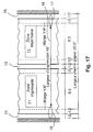
- the writing heads must cover a width corresponding to a double-width strip represented by the reference 18 in FIG. 17 and must be able to be selectively controlled as two groups of independent heads with an intermediate zone 13, FIG. 17 not printed when the printer is used with a single width paper strip feed.
- FIG. 2 represents the printing engine conventionally used with a double width paper strip and in this case the two groups of writing heads T1, T2 are selected for printing in the area 18 and the areas 16 and 17 of the heads a'writing correspond to the areas at the two ends of the printing device which are not used because they are surplus in the case considered of a single double-width strip.
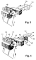
- Figure 3 shows the same print engine used to print two strips of single width paper separated by a margin.
- the write heads are controlled as two groups of selectable heads T1, T2, independently and separated by a space of unused write heads 13 which delimits the margin between the two strips.
- the paper passage (figure 17) must be at least 18.5 "(46.99 cm) to allow the passage of the two 8.5" (21.59 cm) strips. ) and the possibility of having two 0.5 "(1.27 cm) margins at the edge of the paper paths and a 0.5" (1.27 cm) margin between the two strips.
- the two single width bands because both provided with two lateral drive bands, can be used directly on other standard shaping devices, which would not be the case with the two half bands obtained from '' a single double width strip cut in the middle, which would each have only one lateral drive strip and, moreover, located on different sides.
- FIG. 4 represents the use of the printer according to the invention for printing using two groups of heads T1, T2 selectively controlled two strips of single width paper 30, 31 in recto parallel printing.
- the second strip 31 which circulates on the right path of the printer is translated by a translation device constituted by a first turning bar 40 and a second turning bar 41 so as to collate the two strips 30 and 31.
- Each of the print heads T1, T2 is controlled with a well-defined offset to allow temporary compensation for the spatial offset resulting from the two-bar translation system. The possibility of working in stretched bands inside the collation printer thus obtained allows excellent control of the register.
- the cost of the collector function is greatly reduced compared to that of the state of the art which is generally made up of as many personalization printers as of strips to be superimposed.
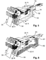
- FIG. 5 shows how the printer of the invention can be easily used for double-sided printing of a single width web by associating with the printer controlled according to two groups of printer heads a double turning device and direction reversal consisting, by way of illustrative but non-limiting example, of a first turning bar 50 causing the strip 30R leaving the left path of the printer to pass transversely below the latter and a second turning bar 51 which causes the strip to return parallel and in the opposite direction along the right path.
- a roller 52 then changes down the direction of the web and a second roller 53 again changes the direction of the printing web to make it move parallel to the path.
- a last roller 54 makes it possible to bring the strip 30 to enter the second path of the printer situated on the right to allow printing by the second group of heads T2 on the back side 30V of the strip which leaves printed on its back on the right side of the printer.
- the use of a well-defined offset between the commands of the heads of the two halves of the writing station makes it possible to guarantee the register and this all the better since the strip can be extended.
- the printer proposed therefore allows extremely flexible use without any modification of the production rate on the page.
- the invention can be used as shown in FIG. 6 by associating with each group of writing heads T1, T2 a respective supply with colored ink. different C1, C2.
- the printer is then fed by a single wide strip which returns by the left path of the printer to pass under the head gourd T1 and after having passed through a return device without turning, the strip is again printed by the second group of heads T2 of the printer supplied to it by the second ink color C2.
- the inking box of the print engine is partitioned in the middle and provisions have been made to supply independently each of the two half boxes thus obtained.
- the return device without turning consists of a first turning bar 60 for bringing the paper strip of the left path transversely to the directions of travel of the printer. Then a downward deflection bar 61 brings this strip vertically and a deflection bar 62 returns the horizontal strip in an opposite direction going from right to left, another reversal bar 63 replaces the strip parallel to the straight path and below this in the direction of the second printing unit T2. Finally, a last bar 64 modifies the direction of the strip to bring its front face towards the second group of printheads.
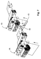
- FIG. 7 represents how two printers of the previous type placed in line make it possible to print two colors on the same double-width paper strip by simply interposing between the two print motors 1A, 1B a deflection roller 42 downwards and a deflection roller 43 towards the inlet of the second print engine.
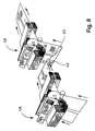
- This same printer constituted by two print engines 1A, 1B provided that each of the two groups of heads T1, T2, T'1, T'2 is selectively controlled and that each of the engines is supplied with ink of different colors will allow printing on two strips of single-sided single-sided paper with two colors on the front as shown in Figure 8.
- the same printer using two print engines 1A and 1B will allow the printing in parallel of two strips of single width paper with two colors on the front and the collation of the two strips using a collation device constituted by the inversion rollers 40, 41 as shown in FIG. 9.
- FIG. 10 shows how two printing motors 1A, 1B described above make it possible to print double-sided on a double width web by inserting between the two motors a turning device of the strip constituted by way of illustrative but nonlimiting example by a turning bar 70, a change of direction bar 71 orienting the strip downwards, a change of direction bar 72 orienting the strip horizontally, a second reversal 73 and a direction change bar 74 orienting the strip towards the entry of the second motor 1B.
- a turning device of the strip constituted by way of illustrative but nonlimiting example by a turning bar 70, a change of direction bar 71 orienting the strip downwards, a change of direction bar 72 orienting the strip horizontally, a second reversal 73 and a direction change bar 74 orienting the strip towards the entry of the second motor 1B.
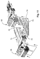
- FIG. 11 represents the use of the same architecture for the printing of two strips of single width paper in parallel in monochrome duplex printing.
- the invention has the same practical advantage as that already mentioned in the case of two-color printing.
- FIG. 12 shows how, by adding to a device such as that of FIG. 11, a lateral translation device constituted by two 45 ° turning bars, 40, 41, it is possible to obtain a collector with two bands, each band being personalized both on the front and back.
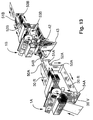
- FIG. 13 shows in schematic form how two printers of the type of those described in FIG. 5 can be adapted to allow two-color and double-sided printing of a single wide strip.
- a first printer of the type of FIG. 5 is associated with a second printer of the same type but in which the input and output paths have been reversed. That is to say the entry path of the second printer 1B being done from the right opposite the second group of writing heads T'2 of the second printer and the return device with reversal ensuring the return with reversal from the right path to the left path so that the strip arrives on its reverse side opposite the first group of heads T'1 located on the left path of the second printer 1B.
- the first print engine 1A is supplied with a color ink C1 and the second print engine 1B is supplied with a color ink C2 and thus the single width web is printed in two colors C1, C2 on each of its two faces.
- FIG. 14 also illustrates the great flexibility of use offered by the printer of the invention when it is combined with another printer of the same type for printing in parallel both a single web strip in two-color front and a single web double-sided width each side of which is monochrome but of different color.
- a first printer engine 1A whose groups of heads T1, T2 are supplied with ink of color C1 and in which two simple width strips 30R, 31R pass, the left strip being turned over before introduction into the second printer motor by a conventional turning device constituted by way of non-limiting illustration of a turning bar 70, a turning bar down 71, a horizontal turning bar 72, a second turning bar 73 and a deflection bar 74 towards the entry of the left channel of the second printer 1B.
- FIG. 15 corresponds to the architecture of FIG. 14 with, simply for the second printer engine, a double inking tray thanks to which the group of heads T'1 is supplied with an ink of color C1 identical to l ink supply of the first printer engine 1A and the second group of heads T'2 of the second printer engine 1B is supplied with an ink of different color C2.
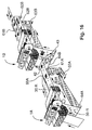
- FIG. 16 represents an architecture in which two printer engines of the type of FIG. 6 are used with a partitioned inking box to allow continuous printing of four-color images from two ink colors C1, C2 contained in the inking boxes of the first motor 1A and of the other two ink colors C3, C4 placed in the second motor 1B.
- the ink C1 used to supply the first group of write heads T1 of the first motor 1A, the ink C2 the second group of heads T2 of the first motor 1A which receives the strip after it has passed into the first group head and in the return device without turning.
- the strip exits through the right path of the first 1A motor to enter the right lane of the second motor 1B which will print the front side with colored ink C3 supplying the second group T'2 of the second motor 1B. Then the ribbon after passing through a return device without turning returns to the left track of the second motor 1B and the color ink C4 is printed using the first group of heads T'2 of the second motor.
Landscapes
- Printers Characterized By Their Purpose (AREA)
- Color, Gradation (AREA)
- Character Spaces And Line Spaces In Printers (AREA)
- Dot-Matrix Printers And Others (AREA)
Claims (17)
- Drucker mit einer einzigen Druckvorrichtung und einer einzigen berührungsfreien Heizvorrichtung, dadurch gekennzeichnet, daß er eine Druckbreite und eine Papierdurchgangsbreite aufweist, die größer als diejenige einer doppelten Standardbreite ist und zwischen 18,5 Zoll (46,99 cm) und 20,5 Zoll (52,07 cm) beträgt, sowie eine selektive Steuerung der Schreibköpfe, um diese entweder als eine einzige Gruppe zum Bedrucken einer zentrierten Bahn doppelter Standardbreite zu verwenden oder um sie als zwei Gruppen von Köpfen (T1, T2) zum gleichzeitigen Bedrucken zweier Bahnen einfacher Standardbreite, die durch einen Zwischenraum (13) voneinander getrennt sind, zu verwenden, wobei die beiden Gruppen von Köpfen (T1, T2) oder jede Gruppe von Köpfen mit einer Druckfarbe (C1) versorgt werden können.
- Drucker nach Anspruch 1, dadurch gekennzeichnet, daß die selektive Steuerung der Köpfe zum Drucken eines Motivs mittels jeder Gruppe von Köpfen auf einer einfachen Bahn den räumlichen Versatz berücksichtigt, der durch eine Zweistreifen-Zusammentragvorrichtung mit zwei Wendestangen (40, 41) hervorgerufen wird.
- Drucker nach Anspruch 1, dadurch gekennzeichnet, daß er eine Vorrichtung (60 bis 64) zum Umlenken ohne Wenden einer mittels einer ersten Gruppe von Köpfen (T1) mit einer ersten Druckfarbe (C1) auf einer Seite bedruckten Bahn einfacher Standardbreite zu der zweiten Gruppe von Köpfen (T2) aufweist, die mit einer anderen Druckfarbe (C2) versorgt wird, um einen Zweifarbendruck zu ermöglichen.
- Drucker nach Anspruch 1, dadurch gekennzeichnet, daß er eine Vorrichtung (50 bis 54) zum Umlenken mit Wenden einer mittels der ersten Gruppe von Köpfen (C1) auf einer Seite in einer Farbe (T1) bedruckten Bahn einfacher Standardbreite zu der zweiten Gruppe von Köpfen (C2) aufweist, die mit Druckfarbe (C1) derselben Farbe versorgt wird, um ein Bedrucken der Vorderseite und der Rückseite mit derselben Farbe zu ermöglichen.
- Drucker nach Anspruch 3 oder Anspruch 4, dadurch gekennzeichnet, daß die selektive Steuerung der Gruppen von Köpfen so ausgeführt wird, daß der von der Umlenkvorrichtung hervorgerufene räumliche Versatz berücksichtigt wird.
- Drucker nach Anspruch 3, dadurch gekennzeichnet, daß zwei Zweifarbendruck-Drucker (1A, 1B) in Reihe vorgesehen sind, wobei der zweite Drucker (1B) mit der zweiten Gruppe von Köpfen (T'2) auf eine erste Seite druckt und die Vorrichtung (60B bis 64B) zum Umlenken ohne Wenden die Führung der aus der zweiten Gruppe von Köpfen (T'2) des zweiten Druckers austretenden Bahn zu der ersten Gruppe von Köpfen (T'1) des zweiten Druckers gewährleistet, die auf der linken Seite des zweiten Druckers angeordnet ist.
- Drucker nach Anspruch 4, dadurch gekennzeichnet, daß zwei Drucker zum Bedrucken der Vorderseite und der Rückseite in Reihe angeordnet sind, wobei der zweite Drucker auf die Rückseite der Bahn einfacher Standardbreite mittels der zweiten Gruppe von Köpfen (T'2) die zweite Farbe (C2) des zweifarbigen Motivs aufdruckt, wobei die Vorrichtung (50B bis 54B) zum Umlenken mit Wenden des zweiten Druckers (1B) die Führung der aus der auf der rechten Seite des Druckers angeordneten Gruppe von Köpfen (T'2) austretenden Bahn zu der auf der linken Seite des Druckers (1B) angeordneten Gruppe von Köpfen (T'1) gewährleistet, um auf der Vorderseite der Bahn das Drucken des Motivs in der zweiten Farbe (C1) auszuführen.
- Drucker nach einem der vorhergehenden Ansprüche, dadurch gekennzeichnet, daß jede Gruppe von Köpfen oder die beiden Gruppen von Köpfen mit einer Druckfarbe versorgt werden.
- Drucker nach Anspruch 1, dadurch gekennzeichnet, daß zwei Drucker in Reihe angeordnet sind, wobei die beiden Bahnen einfacher Standardbreite oder die Bahn doppelter Standardbreite, die aus dem ersten Drucker (1A) austreten bzw. austritt, von einer Wendevorrichtung (70 bis 74) vor dem Eintreten in den zweiten Drucker gewendet werden bzw. wird.
- Drucker nach Anspruch 1, dadurch gekennzeichnet, daß zwei Drucker mit verschiedenen Druckfarben in Reihe vorgesehen sind, wobei die aus dem linken Weg des ersten Druckers (1A) austretende Bahn einfacher Standardbreite von einer Wendevorrichtung (70 bis 74) vor dem Eintreten in den linken Weg des zweiten Druckers (1B) gewendet wird, um mit einer anderen Druckfarbe bedruckt zu werden.
- Drucker nach Anspruch 1, dadurch gekennzeichnet, daß zwei Drucker in Reihe vorgesehen sind, von denen der zweite mit zwei unterschiedlichen Druckfarben (C1, C2) versorgt wird, die jeweils einer Gruppe von Köpfen (T'1, T'2) zugeordnet sind, wobei die aus dem linken Weg des ersten Druckers austretende Bahn in einer Wendevorrichtung (70 bis 73) gewendet wird, um in den der ersten Gruppe von Köpfen (T'1) des zweiten Druckers (1B), die mit Druckfarbe (C1) derselben Farbe wie der erste Drucker (1A) versorgt wird, entsprechenden linken Weg eingeführt zu werden, während die aus dem ersten Drucker (1A) austretende rechte Bahn direkt in den zweiten Drucker (1B) zurückkehrt, um mittels der mit der zweiten Farbe (C2) versorgten zweiten Gruppe von Köpfen (T'2) des zweiten Druckers (AB) bedruckt zu werden.
- Drucker nach einem der vorhergehenden Ansprüche, dadurch gekennzeichnet, daß die Druckvorrichtung vom magnetographischen Typ ist.
- Drucker nach einem der Ansprüche 1 bis 11, dadurch gekennzeichnet, daß die Druckvorrichtung vom elektrophotographischen Typ ist.
- Drucker nach einem der Ansprüche 1 bis 11, dadurch gekennzeichnet, daß die Druckvorrichtung vom ionographischen Typ ist.
- Drucker nach einem der Ansprüche 1 bis 11, dadurch gekennzeichnet, daß die Druckvorrichtung vom thermischen Typ ist.
- Drucker nach einem der Ansprüche 1 bis 11, dadurch gekennzeichnet, daß die Druckvorrichtung vom Typ Tintenstrahl ist.
- Drucker nach einem der Ansprüche 6 bis 11, dadurch gekennzeichnet, daß eine erste Druckvorrichtung von einem Typ ist, der einem der Ansprüche 13 bis 16 entspricht, und die zweite Druckvorrichtung von einem anderen Typ, der einem der Ansprüche 13 bis 16 entspricht.
Applications Claiming Priority (2)
| Application Number | Priority Date | Filing Date | Title |
|---|---|---|---|
| FR9315388A FR2713989B1 (fr) | 1993-12-21 | 1993-12-21 | Imprimante à haute cadence d'impression et utilisations d'une telle imprimante. |
| FR9315388 | 1993-12-21 |
Publications (2)
| Publication Number | Publication Date |
|---|---|
| EP0659569A1 EP0659569A1 (de) | 1995-06-28 |
| EP0659569B1 true EP0659569B1 (de) | 1997-11-05 |
Family
ID=9454176
Family Applications (1)
| Application Number | Title | Priority Date | Filing Date |
|---|---|---|---|
| EP94402955A Expired - Lifetime EP0659569B1 (de) | 1993-12-21 | 1994-12-20 | Hochgeschwindigkeitsdrucker |
Country Status (6)
| Country | Link |
|---|---|
| US (1) | US6120142A (de) |
| EP (1) | EP0659569B1 (de) |
| JP (1) | JPH082017A (de) |
| CA (1) | CA2138616A1 (de) |
| DE (1) | DE69406638T2 (de) |
| FR (1) | FR2713989B1 (de) |
Cited By (1)
| Publication number | Priority date | Publication date | Assignee | Title |
|---|---|---|---|---|
| US6811252B2 (en) | 2000-07-11 | 2004-11-02 | Textilma Ag | Installation for continuously producing an imprinted textile strip, especially a label strip |
Families Citing this family (65)
| Publication number | Priority date | Publication date | Assignee | Title |
|---|---|---|---|---|
| JP2979499B2 (ja) * | 1996-03-14 | 1999-11-15 | 株式会社ミヤコシ | 表裏印字装置 |
| US5751299A (en) * | 1996-03-22 | 1998-05-12 | Lexmark International, Inc. | Combined electrophotographic and ink jet printing |
| JP3530722B2 (ja) | 1996-10-08 | 2004-05-24 | キヤノン株式会社 | インクジェット記録装置およびインクジェット記録方法 |
| EP0967529B1 (de) * | 1996-10-17 | 2001-08-16 | Océ Printing Systems GmbH | Verfahren zum beidseitigen Bedrucken eines bandförmigen Endbildträgers |
| US6201595B1 (en) | 1996-10-17 | 2001-03-13 | Oce Printing Systems Gmbh | Modular electrophotographic color printer |
| GB9701874D0 (en) | 1997-01-30 | 1997-03-19 | Ici Plc | Thermal transfer printer |
| JP3630979B2 (ja) * | 1998-04-27 | 2005-03-23 | キヤノン株式会社 | 画像形成装置 |
| DE29919094U1 (de) * | 1999-10-29 | 1999-12-30 | Océ Printing Systems GmbH, 85586 Poing | Drucksystem für Paralleldruck mit versetzten Druckseiten auf zwei Aufzeichnungsträger |
| JP2001180156A (ja) * | 1999-12-28 | 2001-07-03 | Toppan Forms Co Ltd | 帳票の製本システムおよび製本方法 |
| CN1205034C (zh) | 2000-08-31 | 2005-06-08 | 泰克斯蒂尔玛股份公司 | 用于连续生产印刷的纺织带、特别是印刷的标签带的设备 |
| WO2002040283A1 (de) * | 2000-11-15 | 2002-05-23 | Textilma Ag | Anlage zum bedrucken eines textilbandes, insbesondere eines etikettenbandes |
| TW550184B (en) | 2000-12-01 | 2003-09-01 | Benq Corp | Method for increasing printing speed of printing device |
| US6615717B1 (en) * | 2001-06-18 | 2003-09-09 | Xerox Corporation | Symmetrical parallel duplex paper path device |
| JP2003112450A (ja) * | 2001-10-09 | 2003-04-15 | Fuji Photo Film Co Ltd | 画像記録方法および装置 |
| AU2002364255A1 (en) | 2001-12-24 | 2003-07-15 | Digimarc Id Systems, Llc | Covert variable information on id documents and methods of making same |
| US7207494B2 (en) | 2001-12-24 | 2007-04-24 | Digimarc Corporation | Laser etched security features for identification documents and methods of making same |
| US7694887B2 (en) | 2001-12-24 | 2010-04-13 | L-1 Secure Credentialing, Inc. | Optically variable personalized indicia for identification documents |
| WO2003088144A2 (en) | 2002-04-09 | 2003-10-23 | Digimarc Id Systems, Llc | Image processing techniques for printing identification cards and documents |
| US7824029B2 (en) * | 2002-05-10 | 2010-11-02 | L-1 Secure Credentialing, Inc. | Identification card printer-assembler for over the counter card issuing |
| JP4022901B2 (ja) * | 2002-05-24 | 2007-12-19 | 株式会社ミヤコシ | 新聞の製作方法 |
| IL151354A (en) * | 2002-08-20 | 2005-11-20 | Zach Moshe | Multi-printhead digital printer |
| US7804982B2 (en) | 2002-11-26 | 2010-09-28 | L-1 Secure Credentialing, Inc. | Systems and methods for managing and detecting fraud in image databases used with identification documents |
| ATE491190T1 (de) | 2003-04-16 | 2010-12-15 | L 1 Secure Credentialing Inc | Dreidimensionale datenspeicherung |
| US6811239B1 (en) * | 2003-05-20 | 2004-11-02 | The Procter & Gamble Company | Method of inkjet printing in high efficiency production of hygienic articles |
| GB0312591D0 (en) * | 2003-06-02 | 2003-07-09 | Fisco Tools Ltd | Manufacture of tape measures |
| US7387458B2 (en) * | 2003-08-13 | 2008-06-17 | Paxar Americas, Inc. | Printer and method of printing with a plurality of selectable registration sensors |
| US7918530B2 (en) | 2006-02-03 | 2011-04-05 | Rr Donnelley | Apparatus and method for cleaning an inkjet printhead |
| US7771010B2 (en) * | 2006-02-03 | 2010-08-10 | Rr Donnelley | Apparatus for printing using a plurality of printing cartridges |
| US7967407B2 (en) * | 2006-02-03 | 2011-06-28 | R.R. Donnelley | Use of a sense mark to control a printing system |
| US8172363B2 (en) * | 2006-06-22 | 2012-05-08 | Electronics For Imaging, Inc. | Apparatus and methods for full-width wide format inkjet printing |
| US20090021542A1 (en) * | 2007-06-29 | 2009-01-22 | Kanfoush Dan E | System and method for fluid transmission and temperature regulation in an inkjet printing system |
| US8753026B2 (en) | 2007-06-29 | 2014-06-17 | R.R. Donnelley & Sons Company | Use of a sense mark to control a printing system |
| US20090010699A1 (en) * | 2007-07-05 | 2009-01-08 | Graphic Converting, Inc. | System for simultaneously modifying a plurality of areas on a sheet |
| JP5195040B2 (ja) * | 2008-05-30 | 2013-05-08 | セイコーエプソン株式会社 | 印刷装置 |
| JP5481047B2 (ja) * | 2008-08-29 | 2014-04-23 | タカタ株式会社 | インクジェット染色装置 |
| FR2936443B1 (fr) | 2008-09-30 | 2010-10-01 | Nipson Sas | Elements de support de picots pour dispositif d'amenee de support d'impression a laize d'un appareil d'impression "a la demande" non-impact |
| JP5638003B2 (ja) | 2009-01-12 | 2014-12-10 | ユニバーシティ オブ マサチューセッツ ローウェル | ポリイソブチレン系ポリウレタン |
| JP5630019B2 (ja) * | 2010-01-14 | 2014-11-26 | 株式会社リコー | 連続紙印刷装置 |
| JP2011201294A (ja) | 2010-03-01 | 2011-10-13 | Ricoh Co Ltd | 連続紙用画像形成装置の制御装置、連続紙用画像形成装置、制御方法及び制御プログラム |
| JP2011207207A (ja) | 2010-03-12 | 2011-10-20 | Ricoh Co Ltd | 連続紙両面プリンタおよび印刷方法 |
| RU2516836C1 (ru) * | 2010-03-31 | 2014-05-20 | Кэнон Кабусики Кайся | Система печати, система обработки листов и устройство переключения пути листа |
| EP2554391A1 (de) * | 2010-03-31 | 2013-02-06 | Canon Kabushiki Kaisha | Drucksystem, blattbehandlungssystem und vorrichtung für blattrichtungswechsel |
| JP5789940B2 (ja) * | 2010-09-15 | 2015-10-07 | 株式会社リコー | 印刷装置、並びにその印刷制御方法及び印刷制御プログラム |
| US20120073460A1 (en) * | 2010-09-29 | 2012-03-29 | Goss International Americas, Inc. | Variable cutoff printing press and method for double printing |
| US9251458B2 (en) | 2011-09-11 | 2016-02-02 | Féinics Amatech Teoranta | Selective deposition of magnetic particles and using magnetic material as a carrier medium to deposit nanoparticles |
| EP2741917B1 (de) | 2011-08-12 | 2019-05-22 | R. R. Donnelley & Sons Company | Vorrichtung und verfahren zum anordnen von tintenstrahlpatronen in einem träger |
| SE537486C2 (sv) * | 2012-03-05 | 2015-05-19 | Tetra Laval Holdings & Finance | System och sätt för tryckning |
| CN103373090A (zh) * | 2012-04-12 | 2013-10-30 | 常熟市昌盛经编织造有限公司 | 一种含有加热装置的双导轴机头组件 |
| US8888208B2 (en) | 2012-04-27 | 2014-11-18 | R.R. Donnelley & Sons Company | System and method for removing air from an inkjet cartridge and an ink supply line |
| US9926399B2 (en) | 2012-11-21 | 2018-03-27 | University Of Massachusetts | High strength polyisobutylene polyurethanes |
| EP2784724A3 (de) | 2013-03-27 | 2015-04-22 | Féinics AmaTech Teoranta | Selektive Abscheidung von magnetischen Teilchen und Verwendung von magnetischem Material als Trägermedium zur Abscheidung anderer Teilchen |
| DE102013107451A1 (de) | 2013-07-15 | 2015-01-15 | Océ Printing Systems GmbH & Co. KG | Druckeinrichtung zum beidseitigen Bedrucken eines bandförmigen Bedruckstoffs |
| CN104924755B (zh) * | 2014-03-18 | 2016-06-22 | 梁健 | 一种同步单双面数码喷绘机及其绕布方法 |
| WO2017151177A1 (en) | 2016-03-04 | 2017-09-08 | R.R. Donnelley & Sons Company | Printhead maintenance station and method of operating same |
| CN207291314U (zh) | 2016-05-09 | 2018-05-01 | R.R.当纳利父子公司 | 油墨供应单元 |
| DE102016209280A1 (de) * | 2016-05-30 | 2017-11-30 | Heidelberger Druckmaschinen Ag | Vorrichtung zum Bedrucken einer Bahn aus Bedruckstoff |
| WO2018059969A1 (en) * | 2016-09-28 | 2018-04-05 | OCE Holding B.V. | Printing system for printing a plurality of images on a first web and on a second web and a method thereof |
| WO2018165273A1 (en) | 2017-03-07 | 2018-09-13 | Cardiac Pacemakers, Inc. | Hydroboration/oxidation of allyl-terminated polyisobutylene |
| US10370214B2 (en) | 2017-05-31 | 2019-08-06 | Cryovac, Llc | Position control system and method |
| US10835638B2 (en) | 2017-08-17 | 2020-11-17 | Cardiac Pacemakers, Inc. | Photocrosslinked polymers for enhanced durability |
| KR102049276B1 (ko) * | 2018-05-31 | 2019-11-27 | (주)그린파즈 | 토양서식 해충 유인제 및 그 제조방법 |
| CN110126461A (zh) * | 2019-03-29 | 2019-08-16 | 上海工程技术大学 | 写真一体设备 |
| CN113580768B (zh) * | 2021-09-13 | 2022-08-23 | 珠海市慧虹智能科技有限公司 | 一种防溅射的卷尺高速喷墨打印机 |
| CN116061552B (zh) * | 2023-01-12 | 2024-02-13 | 新世纪标志(深圳)有限公司 | 一种多色组合式集装箱贴自动化印刷机 |
| DE102023134235B3 (de) | 2023-12-07 | 2024-10-24 | Koenig & Bauer Ag | Verfahren zum Ausrichten von Non Impact Druckköpfen |
Family Cites Families (17)
| Publication number | Priority date | Publication date | Assignee | Title |
|---|---|---|---|---|
| US4208666A (en) * | 1978-10-23 | 1980-06-17 | The Mead Corporation | Multiple copy ink jet printer |
| EP0026890A3 (de) * | 1979-10-09 | 1982-10-20 | Teletype Corporation | Papierfördermechanismus für ein Druckwerk |
| JPS5769071A (en) * | 1980-10-17 | 1982-04-27 | Fuji Xerox Co Ltd | Duplex recorder |
| JPS5782069A (en) * | 1980-11-10 | 1982-05-22 | Ricoh Co Ltd | Ink jet recording device |
| DE3232875A1 (de) * | 1982-09-02 | 1984-03-08 | Mannesmann AG, 4000 Düsseldorf | Papiertransportvorrichtung fuer drucker, insbesondere fuer matrixdrucker |
| US4591884A (en) * | 1983-03-10 | 1986-05-27 | Canon Kabushiki Kaisha | Multi-function image recording apparatus |
| JPS61112667A (ja) * | 1984-11-06 | 1986-05-30 | Fuji Xerox Co Ltd | カラ−プリンタ |
| JPH0661968B2 (ja) * | 1985-08-10 | 1994-08-17 | 株式会社リコー | 記録装置 |
| US4788563A (en) * | 1986-05-19 | 1988-11-29 | Canon Kabushiki Kaisha | Recording apparatus |
| US5119108A (en) * | 1990-03-29 | 1992-06-02 | Mutoh Industries Ltd. | Method and apparatus for thermal recording with overlapped thermal print heads |
| US5260760A (en) * | 1990-11-27 | 1993-11-09 | Mita Industrial Co., Ltd. | Image forming apparatus with auxiliary image forming mechanism |
| JPH04321062A (ja) * | 1991-04-22 | 1992-11-11 | Hitachi Koki Co Ltd | 連続印刷用紙の両面印刷装置 |
| DE4129277A1 (de) * | 1991-09-03 | 1993-03-04 | Siemens Nixdorf Inf Syst | Elektrofotografisches simultan-doppeldrucksystem |
| US5220346A (en) * | 1992-02-03 | 1993-06-15 | Xerox Corporation | Printing processes with microwave drying |
| DE69304774T2 (de) * | 1992-05-01 | 1997-02-20 | Hewlett Packard Co | Heizgebläseanordnung in einem Farbstrahldrucker |
| DE59400956D1 (de) * | 1993-05-19 | 1996-12-05 | Siemens Nixdorf Inf Syst | Elektrografische druckeinrichtung zum bedrucken von bandförmigen aufzeichnungsträgern unterschiedlicher bandbreite |
| DE59400220D1 (de) * | 1994-08-19 | 1996-05-23 | Siemens Nixdorf Inf Syst | Wendeeinrichtung für bandförmige Aufzeichnungsträger |
-
1993
- 1993-12-21 FR FR9315388A patent/FR2713989B1/fr not_active Expired - Fee Related
-
1994
- 1994-12-20 CA CA002138616A patent/CA2138616A1/fr not_active Abandoned
- 1994-12-20 DE DE69406638T patent/DE69406638T2/de not_active Expired - Lifetime
- 1994-12-20 EP EP94402955A patent/EP0659569B1/de not_active Expired - Lifetime
- 1994-12-21 JP JP6335560A patent/JPH082017A/ja active Pending
-
1997
- 1997-05-27 US US08/863,716 patent/US6120142A/en not_active Expired - Lifetime
Cited By (1)
| Publication number | Priority date | Publication date | Assignee | Title |
|---|---|---|---|---|
| US6811252B2 (en) | 2000-07-11 | 2004-11-02 | Textilma Ag | Installation for continuously producing an imprinted textile strip, especially a label strip |
Also Published As
| Publication number | Publication date |
|---|---|
| DE69406638T2 (de) | 1998-06-25 |
| FR2713989B1 (fr) | 1996-01-12 |
| CA2138616A1 (fr) | 1995-06-22 |
| EP0659569A1 (de) | 1995-06-28 |
| DE69406638D1 (de) | 1997-12-11 |
| US6120142A (en) | 2000-09-19 |
| FR2713989A1 (fr) | 1995-06-23 |
| JPH082017A (ja) | 1996-01-09 |
Similar Documents
| Publication | Publication Date | Title |
|---|---|---|
| EP0659569A1 (de) | Hochgeschwindigkeitsdrucker und seine Verwendungen | |
| JP5195040B2 (ja) | 印刷装置 | |
| JP2979499B2 (ja) | 表裏印字装置 | |
| JP5812624B2 (ja) | プリント方法およびプリント装置 | |
| JPH08216467A (ja) | 表裏印字装置 | |
| JP5035036B2 (ja) | 記録装置 | |
| JP6008639B2 (ja) | プリント方法およびプリント装置 | |
| JP2995465B2 (ja) | インクジェットプリントシステムにおけるランダム加工装置 | |
| JP2010000762A (ja) | 印刷装置 | |
| EP1772280B1 (de) | Tintenstrahlaufzeichnungsgerät für strahlungshärtbare Tinten | |
| JP5263427B2 (ja) | 記録装置及び記録方法 | |
| US8220897B2 (en) | Computer based method and system for adjusting page placement on a continuous feed print engine | |
| US20170106665A1 (en) | Front and back printing on security document substrates | |
| US8721019B2 (en) | Apparatus and method for treatment of printed ink images | |
| JP3610252B2 (ja) | 記録装置 | |
| JP2009248428A (ja) | インクジェット記録方法およびインクジェット記録装置 | |
| JP2979398B1 (ja) | インクジェットプリンタにおける左右印刷同期ずれ検知方法 | |
| JP2604954B2 (ja) | 記録ヘッド制御機構 | |
| JP2979397B1 (ja) | インクジェットプリンタにおける左右印刷同期ずれ検出装置 | |
| JP2004351677A (ja) | インクジェットプリント方法及びプリンタ | |
| JP2000108358A (ja) | インクジェットプリンタによる印刷状態の目視確認方法 | |
| JP2004351676A (ja) | 画像記録方法及び装置 | |
| JP2013039838A (ja) | 印刷装置 | |
| BE901555A (fr) | Machine rotative d'impression combinee. | |
| KR0132868B1 (ko) | 인쇄방법 및 장치 |
Legal Events
| Date | Code | Title | Description |
|---|---|---|---|
| PUAI | Public reference made under article 153(3) epc to a published international application that has entered the european phase |
Free format text: ORIGINAL CODE: 0009012 |
|
| AK | Designated contracting states |
Kind code of ref document: A1 Designated state(s): BE CH DE ES FR GB IT LI NL |
|
| 17P | Request for examination filed |
Effective date: 19950810 |
|
| GRAG | Despatch of communication of intention to grant |
Free format text: ORIGINAL CODE: EPIDOS AGRA |
|
| 17Q | First examination report despatched |
Effective date: 19960909 |
|
| GRAH | Despatch of communication of intention to grant a patent |
Free format text: ORIGINAL CODE: EPIDOS IGRA |
|
| GRAH | Despatch of communication of intention to grant a patent |
Free format text: ORIGINAL CODE: EPIDOS IGRA |
|
| GRAA | (expected) grant |
Free format text: ORIGINAL CODE: 0009210 |
|
| AK | Designated contracting states |
Kind code of ref document: B1 Designated state(s): BE CH DE ES FR GB IT LI NL |
|
| PG25 | Lapsed in a contracting state [announced via postgrant information from national office to epo] |
Ref country code: NL Free format text: LAPSE BECAUSE OF FAILURE TO SUBMIT A TRANSLATION OF THE DESCRIPTION OR TO PAY THE FEE WITHIN THE PRESCRIBED TIME-LIMIT Effective date: 19971105 Ref country code: ES Free format text: THE PATENT HAS BEEN ANNULLED BY A DECISION OF A NATIONAL AUTHORITY Effective date: 19971105 |
|
| REG | Reference to a national code |
Ref country code: CH Ref legal event code: EP |
|
| GBT | Gb: translation of ep patent filed (gb section 77(6)(a)/1977) |
Effective date: 19971106 |
|
| ITF | It: translation for a ep patent filed | ||
| REF | Corresponds to: |
Ref document number: 69406638 Country of ref document: DE Date of ref document: 19971211 |
|
| PG25 | Lapsed in a contracting state [announced via postgrant information from national office to epo] |
Ref country code: LI Free format text: LAPSE BECAUSE OF NON-PAYMENT OF DUE FEES Effective date: 19971231 Ref country code: CH Free format text: LAPSE BECAUSE OF NON-PAYMENT OF DUE FEES Effective date: 19971231 Ref country code: BE Free format text: LAPSE BECAUSE OF NON-PAYMENT OF DUE FEES Effective date: 19971231 |
|
| NLV1 | Nl: lapsed or annulled due to failure to fulfill the requirements of art. 29p and 29m of the patents act | ||
| BERE | Be: lapsed |
Owner name: S.A. NIPSON Effective date: 19971231 |
|
| REG | Reference to a national code |
Ref country code: CH Ref legal event code: PL |
|
| PLBE | No opposition filed within time limit |
Free format text: ORIGINAL CODE: 0009261 |
|
| STAA | Information on the status of an ep patent application or granted ep patent |
Free format text: STATUS: NO OPPOSITION FILED WITHIN TIME LIMIT |
|
| 26N | No opposition filed | ||
| REG | Reference to a national code |
Ref country code: GB Ref legal event code: IF02 |
|
| PGFP | Annual fee paid to national office [announced via postgrant information from national office to epo] |
Ref country code: GB Payment date: 20101221 Year of fee payment: 17 Ref country code: IT Payment date: 20101221 Year of fee payment: 17 |
|
| PGFP | Annual fee paid to national office [announced via postgrant information from national office to epo] |
Ref country code: FR Payment date: 20111226 Year of fee payment: 18 |
|
| PGFP | Annual fee paid to national office [announced via postgrant information from national office to epo] |
Ref country code: DE Payment date: 20111219 Year of fee payment: 18 |
|
| GBPC | Gb: european patent ceased through non-payment of renewal fee |
Effective date: 20121220 |
|
| REG | Reference to a national code |
Ref country code: FR Ref legal event code: ST Effective date: 20130830 |
|
| REG | Reference to a national code |
Ref country code: DE Ref legal event code: R119 Ref document number: 69406638 Country of ref document: DE Effective date: 20130702 |
|
| PG25 | Lapsed in a contracting state [announced via postgrant information from national office to epo] |
Ref country code: DE Free format text: LAPSE BECAUSE OF NON-PAYMENT OF DUE FEES Effective date: 20130702 |
|
| PG25 | Lapsed in a contracting state [announced via postgrant information from national office to epo] |
Ref country code: GB Free format text: LAPSE BECAUSE OF NON-PAYMENT OF DUE FEES Effective date: 20121220 Ref country code: FR Free format text: LAPSE BECAUSE OF NON-PAYMENT OF DUE FEES Effective date: 20130102 |
|
| PG25 | Lapsed in a contracting state [announced via postgrant information from national office to epo] |
Ref country code: IT Free format text: LAPSE BECAUSE OF NON-PAYMENT OF DUE FEES Effective date: 20121220 |