EP0657062B2 - Veränderbarer hochstromwiderstand und anwendung als schutzelement - Google Patents
Veränderbarer hochstromwiderstand und anwendung als schutzelement Download PDFInfo
- Publication number
- EP0657062B2 EP0657062B2 EP93917545A EP93917545A EP0657062B2 EP 0657062 B2 EP0657062 B2 EP 0657062B2 EP 93917545 A EP93917545 A EP 93917545A EP 93917545 A EP93917545 A EP 93917545A EP 0657062 B2 EP0657062 B2 EP 0657062B2
- Authority
- EP
- European Patent Office
- Prior art keywords
- current
- carbon
- circuit
- variable high
- current resistor
- Prior art date
- Legal status (The legal status is an assumption and is not a legal conclusion. Google has not performed a legal analysis and makes no representation as to the accuracy of the status listed.)
- Expired - Lifetime
Links
- 230000001681 protective effect Effects 0.000 title claims abstract description 23
- OKTJSMMVPCPJKN-UHFFFAOYSA-N Carbon Chemical compound [C] OKTJSMMVPCPJKN-UHFFFAOYSA-N 0.000 claims abstract description 27
- 229910052799 carbon Inorganic materials 0.000 claims abstract description 24
- 230000007704 transition Effects 0.000 claims abstract description 18
- 239000006229 carbon black Substances 0.000 claims abstract description 14
- 239000000463 material Substances 0.000 claims abstract description 11
- 230000002829 reductive effect Effects 0.000 claims abstract description 8
- 239000004065 semiconductor Substances 0.000 claims abstract description 8
- 235000019241 carbon black Nutrition 0.000 claims abstract 12
- 239000004020 conductor Substances 0.000 claims abstract 6
- 239000011230 binding agent Substances 0.000 claims description 25
- 238000000354 decomposition reaction Methods 0.000 claims description 12
- 239000004698 Polyethylene Substances 0.000 claims description 8
- 239000002245 particle Substances 0.000 claims description 8
- 239000007789 gas Substances 0.000 claims description 7
- 230000000670 limiting effect Effects 0.000 claims description 7
- 230000036961 partial effect Effects 0.000 claims description 7
- -1 polyethylene Polymers 0.000 claims description 7
- 229920000573 polyethylene Polymers 0.000 claims description 7
- 239000002861 polymer material Substances 0.000 claims description 6
- 230000009467 reduction Effects 0.000 claims description 6
- IJGRMHOSHXDMSA-UHFFFAOYSA-N Atomic nitrogen Chemical compound N#N IJGRMHOSHXDMSA-UHFFFAOYSA-N 0.000 claims description 4
- 238000000137 annealing Methods 0.000 claims description 4
- 239000011295 pitch Substances 0.000 claims description 4
- 239000011269 tar Substances 0.000 claims description 4
- 239000001993 wax Substances 0.000 claims description 4
- UFHFLCQGNIYNRP-UHFFFAOYSA-N Hydrogen Chemical compound [H][H] UFHFLCQGNIYNRP-UHFFFAOYSA-N 0.000 claims description 2
- 230000000295 complement effect Effects 0.000 claims description 2
- 238000005538 encapsulation Methods 0.000 claims description 2
- 239000001257 hydrogen Substances 0.000 claims description 2
- 229910052739 hydrogen Inorganic materials 0.000 claims description 2
- 238000004519 manufacturing process Methods 0.000 claims description 2
- 229910052757 nitrogen Inorganic materials 0.000 claims description 2
- 229920000728 polyester Polymers 0.000 claims description 2
- 238000005979 thermal decomposition reaction Methods 0.000 claims description 2
- 238000003466 welding Methods 0.000 claims description 2
- 239000012809 cooling fluid Substances 0.000 claims 2
- 239000004519 grease Substances 0.000 claims 2
- 239000011261 inert gas Substances 0.000 claims 1
- 238000005516 engineering process Methods 0.000 abstract description 2
- 239000004071 soot Substances 0.000 description 25
- 230000000694 effects Effects 0.000 description 11
- 230000008859 change Effects 0.000 description 6
- 239000003245 coal Substances 0.000 description 6
- 230000004044 response Effects 0.000 description 6
- 230000001419 dependent effect Effects 0.000 description 5
- 230000008901 benefit Effects 0.000 description 4
- 230000006378 damage Effects 0.000 description 4
- 238000009826 distribution Methods 0.000 description 4
- 229920000642 polymer Polymers 0.000 description 4
- 229920001940 conductive polymer Polymers 0.000 description 3
- 238000010438 heat treatment Methods 0.000 description 3
- 238000005470 impregnation Methods 0.000 description 3
- 238000004904 shortening Methods 0.000 description 3
- 230000001960 triggered effect Effects 0.000 description 3
- 229920000049 Carbon (fiber) Polymers 0.000 description 2
- 230000005540 biological transmission Effects 0.000 description 2
- 239000004917 carbon fiber Substances 0.000 description 2
- 230000001276 controlling effect Effects 0.000 description 2
- 238000011156 evaluation Methods 0.000 description 2
- 239000003925 fat Substances 0.000 description 2
- 238000011049 filling Methods 0.000 description 2
- 238000009413 insulation Methods 0.000 description 2
- 239000007788 liquid Substances 0.000 description 2
- 239000002184 metal Substances 0.000 description 2
- 239000000203 mixture Substances 0.000 description 2
- 239000004033 plastic Substances 0.000 description 2
- 229920003023 plastic Polymers 0.000 description 2
- 238000010791 quenching Methods 0.000 description 2
- 230000000171 quenching effect Effects 0.000 description 2
- 230000001105 regulatory effect Effects 0.000 description 2
- 230000035945 sensitivity Effects 0.000 description 2
- 229920003002 synthetic resin Polymers 0.000 description 2
- 239000000057 synthetic resin Substances 0.000 description 2
- 229920001169 thermoplastic Polymers 0.000 description 2
- 238000012549 training Methods 0.000 description 2
- 238000011144 upstream manufacturing Methods 0.000 description 2
- 230000003213 activating effect Effects 0.000 description 1
- 230000032683 aging Effects 0.000 description 1
- 238000000418 atomic force spectrum Methods 0.000 description 1
- 239000011203 carbon fibre reinforced carbon Substances 0.000 description 1
- 230000015556 catabolic process Effects 0.000 description 1
- 239000000919 ceramic Substances 0.000 description 1
- 239000003610 charcoal Substances 0.000 description 1
- 238000010276 construction Methods 0.000 description 1
- 239000000110 cooling liquid Substances 0.000 description 1
- 230000007423 decrease Effects 0.000 description 1
- 230000003247 decreasing effect Effects 0.000 description 1
- 238000011161 development Methods 0.000 description 1
- 230000018109 developmental process Effects 0.000 description 1
- 238000010292 electrical insulation Methods 0.000 description 1
- 230000005520 electrodynamics Effects 0.000 description 1
- 230000005284 excitation Effects 0.000 description 1
- 238000004880 explosion Methods 0.000 description 1
- 230000002349 favourable effect Effects 0.000 description 1
- 231100001261 hazardous Toxicity 0.000 description 1
- 230000017525 heat dissipation Effects 0.000 description 1
- 239000007791 liquid phase Substances 0.000 description 1
- 238000011068 loading method Methods 0.000 description 1
- 230000007246 mechanism Effects 0.000 description 1
- VNWKTOKETHGBQD-UHFFFAOYSA-N methane Chemical compound C VNWKTOKETHGBQD-UHFFFAOYSA-N 0.000 description 1
- 230000004048 modification Effects 0.000 description 1
- 238000012986 modification Methods 0.000 description 1
- 229920001225 polyester resin Polymers 0.000 description 1
- 239000004645 polyester resin Substances 0.000 description 1
- 229920013716 polyethylene resin Polymers 0.000 description 1
- 239000011148 porous material Substances 0.000 description 1
- 239000000843 powder Substances 0.000 description 1
- 238000003825 pressing Methods 0.000 description 1
- 238000002791 soaking Methods 0.000 description 1
- 125000006850 spacer group Chemical group 0.000 description 1
- 230000008093 supporting effect Effects 0.000 description 1
- 230000003319 supportive effect Effects 0.000 description 1
- 239000011299 tars and pitches Substances 0.000 description 1
- 230000008646 thermal stress Effects 0.000 description 1
- 239000004416 thermosoftening plastic Substances 0.000 description 1
- 238000012546 transfer Methods 0.000 description 1
- 230000003313 weakening effect Effects 0.000 description 1
Images


Classifications
-
- H—ELECTRICITY
- H02—GENERATION; CONVERSION OR DISTRIBUTION OF ELECTRIC POWER
- H02H—EMERGENCY PROTECTIVE CIRCUIT ARRANGEMENTS
- H02H9/00—Emergency protective circuit arrangements for limiting excess current or voltage without disconnection
- H02H9/02—Emergency protective circuit arrangements for limiting excess current or voltage without disconnection responsive to excess current
- H02H9/026—Current limitation using PTC resistors, i.e. resistors with a large positive temperature coefficient
-
- H—ELECTRICITY
- H01—ELECTRIC ELEMENTS
- H01C—RESISTORS
- H01C10/00—Adjustable resistors
- H01C10/10—Adjustable resistors adjustable by mechanical pressure or force
Definitions
- the invention relates to a changeable High current resistance, especially for use as a protective element in power switching technology, with at least carbon as a resistance material. Besides The invention relates to circuits below Use of such a high current resistor. In such circuits, a circuit breaker, a power semiconductor, a contactor or a vacuum contactor should be available as a switching element.
- circuit breakers In low-voltage electrical distributors the circuit breakers for safety reasons maximum short-circuit current to be expected in the event of a short circuit can switch off. This current can be in close to 50 kA or 100 busbars are not specified. Circuit breakers with this switching capacity need at a time that is small in terms of Is a network period, the contacts open and build a high arc voltage around the Limit short-circuit current sufficiently.
- EP-A-0 487 920 describes in detail a PTC element with at least one resistance body made of an electrically conductive polymer composition described with a positive temperature coefficient, in which each resistance body preferably two has parallel surfaces, at least an interface with electrodes for introducing the Current is connected to the PTC element.
- Protective element usable high current resistor the polymer resistance body with its base areas be connected to an electrode, at least a surface a so-called free contact with the associated electrode forms and where a Pressure device is present, which is a print vertically on the electrodes and the bases of the resistance body of the conductive polymer layer. Through electrodynamic repulsion at high Flowing the contact is changed, whereby through simultaneous increase in temperature a liquid phase should form in the polymer material.
- a regulating resistor is known from DE-A-0 272 807 known in which the resistance changes by changing the pressure of an electromagnetic armature on a grain mass that in particular Contains carbon powder.
- a coal pressure regulator is known from ETZ (A) 73, 199 (52), which is due to a pressure-dependent change in the Contact resistance arranged in a columnar manner Charcoal chips or rings based. With this coal pressure regulator a voltage or a current is regulated, by increasing the controlled variable Controlling an electromagnet's increasing magnetic force the prestressing of a column of coal plates counteracts. There are supposed to be changes in resistance be possible by a factor of 300.
- the object of the invention is a High current resistance of the type mentioned in the beginning to improve that with that for guards required safety can be used as a limiter.
- the associated circuits should be specified become.
- a predeterminable current threshold for example, 15 times can thereby call from I in the short circuit condition is exceeded, in a time which is opposite the mains period small, the resistance in the transition zone to about increase 100 times and therefore in a secure manner the short circuit current limit to non-hazardous values.
- Resistance is used in the context of the invention the quotient of the voltage drop across the high-current resistor and understood the current through the resistor.
- the voltage drop effective to the outside results thereby from the current distribution in the extensive area Resistor bodies and series connections of voltage drops on microscopic Level. These voltage drops can occur in the invention High current resistance in the soot and / or carbon particles occur or at the contact zones neighboring particles. Likewise, in particular in the transition zone also electric gas discharges possible between conductive particles.
- the one used there Polymer material made conductive is above one certain temperature that for polyethylene at about 120 ° C, high resistance, with the heating at known elements by the short-circuit current and in particular the area of contact between a metallic electrode and the conductive Polyethylene body for heating the polyethylene surface contributes. Accordingly, in the prior art the PTC thermistor effect can be set so that the Resistance stroke in a thin layer of polyethylene Current limitation causes.
- the fact with the invention exploited that the electrical resistance at a mechanically detachable contact point from the contact force depends in such a way that the resistance with decreasing contact force increases.
- Advantagely can at the detachable contact point Current density can be kept low, so that destruction of the electrode surfaces due to high energy densities be avoided.
- soot or coal layers at least on one Side of the releasable contact point to use because the force-dependent change in resistance in these Materials is great.
- is a fine powder Soot or carbon layer is advantageous as a contact layer. This layer can, for example, from previous ones mechanical or thermal stress originate.
- the protective element has at least one contact surface made of a metallic electrode and a soot or carbon-containing electrically conductive layer or at least one contact surface between two soot and / or carbonaceous layers.
- the current flow goes through this interface.
- the metallic electrode and the soot and / or carbonaceous layers with a Force compressed, which is the contact resistance makes it sufficiently small.
- Exceeding a current threshold due to pressure development between electrode and soot and / or carbonaceous Shifts at a time that is small in comparison at the time of a network period this force is reduced as far as that the resistance in the boundary layer of the Touch surface increases in the desired sense.
- the soot and / or carbonaceous layers are preferably round or rectangular plates, in which the soot or carbon particles are caused by binders be held together.
- the latter binders also define the means to reduce the contact pressure and are accordingly to choose.
- the other means of reduction the contact pressure can either be on the electromagnetic Principle or in the exploitation of piezoelectric Control elements are based. In particular in the latter case is by the externally controllable force the contact pressure can be reduced in a targeted manner.
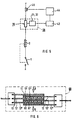
- FIGs 1a and 1b 1 denotes a circuit breaker and 2 a solenoid of the trigger of the circuit breaker 1.
- a so-called arc limiter 3 upstream where, for example, the contacts in the Open a short circuit in the event of a current.
- the circuit breaker 1 with magnetic coil is in FIG. 1b 2 a PTC thermistor 4 upstream, a resistor 5 is connected in parallel.
- the PTC has in the cold Condition of low electrical resistance and im hot state has a high electrical resistance (so-called PTC effect).
- the PTC thermistor is heated through the flowing stream itself, whereby after exceeding it a certain temperature becomes high resistance.
- the parallel resistor 5 is to relieve the PTC thermistor and available to limit the short-circuit current.
- 11 means a layer containing carbon and / or soot, which is pressed between two metallic electrodes 12 and 13 and together with these form a high-current resistor 10.
- the carbon / soot-containing layer 11 can have a thickness of approximately 1 mm and cover an area of 10 cm 2 .
- the layer 11 consists of a porous material composed of individual carbon / soot particles 101, the pore-like cavities of which are filled with a binder 102.
- Polymer materials are used as binders for the above purpose, such as polyethylene, polyester, but also waxes, fats, tars, pitches and the like. Like. in question.
- a transition zone 15 in which the structure is decisive is responsible for the resistance behavior.
- Section A is the interface and transition zone in the Normal state shown, in which case a small one There is resistance.
- section B is the short circuit case shown, in which case a high resistance is present.
- the resistance body from the soot and / or carbonaceous layer and the binder can be prepared in a suitable manner.
- the production of the Layer of soot and / or fine-grained carbon powder initially with the addition of tar and pitch as a binder and pressing the layer at low pressure. By subsequently annealing this layer Temperatures up to 1000 ° C arise electrically conductive, porous layer.
- This annealed body of resistance is then with wax or fats soaked at temperatures above 200 ° C, for example at 300 ° C, in gaseous decomposition products disintegrate to generate the pressure.
- the layer containing soot and / or carbon can, however also produced without annealing and subsequent soaking by choosing a binder that decomposes at least partially even above 200 ° C.
- binders are, for example, polyethylene, Polyester or synthetic resins.
- the soot and / or carbon-containing layer 11 can in alternative training also made of matted carbon fibers exist with a binder and optionally also with additional soot or carbon particles are offset.
- matted carbon fibers for implementation of conductive, porous and very elastic layers are known per se. You can also if necessary be made in paper or foil-like consistency. In order to build a variable resistor to use it is necessary in the surfaces the layers additionally carbon black or carbon very fine and evenly distributed.
- the surface of the metallic electrodes With the described changeable high current resistance 10 with the carbon and / or soot-containing layer 11 and the electrodes 12 and 13, the surface of the metallic electrodes.
- a suitable structuring is the possibility of Control of current density given.
- the carbon and / or soot-containing layer can also be complementary Have structures so that forces are transmitted become.
- FIG. 3 shows an arrangement from FIG. 2 with a layer 11 and electrodes 12 and 13 in an insulating housing 20 introduced with an electromagnet.
- the insulating housing 20 mean 21 an insulating plate for support on the high current resistor 10, 22 a magnet armature, 23 a magnetic yoke, 24 an air gap, 25 a spring force system and 26 the associated current path: the High current resistor 10 as well as armature 22 and yoke 23 are built into the housing 20 so that Spring elements 25 between anchor and yoke a defined Air gap is adjustable and that the spring force on the two electrodes 12 and 13 and the carbon and / or soot-containing layer 11 is transferred. electrical are the current path 26 and the current through the High current resistor 10 connected in series.
- the electrical resistance can now be controlled by the pressure-dependent contact resistance of each of the two Electrodes 12 and 13 for the electrically conductive layer 11 control that the spring forces in whole or in part by magnetic forces between armature 22 and yoke 23 can be compensated.
- This can cause contact resistance up to three powers of ten are increased, the electrical power loss increases sharply and by thermal decomposition of the binder 102 in Decomposition products 103 further the armature closing movement supportive gas dynamic forces like it is described in principle with reference to FIG 2, act. In order to the effective contact pressure is further reduced and the contact resistance increased further.
- the adjustability of the response current of the current limiting device by means of an air gap width to defined short-circuit current values is particularly advantageous in this arrangement.
- the result is a relatively sharp response current, which is a consequence of the I 2 -dependent force profile of the magnetic force between armature and yoke.
- the current limiting mechanism is not controlled by the electrical power loss ((I ⁇ U) dt), but by the instantaneous current (I).
- the control system automatically passes through the current increase via an adjustable response current threshold. As a result, a quick response is achieved while avoiding the faulty shutdown due to longer overcurrents.
- the current-limiting resistor is triggered automatically by the short-circuit current.
- the moment for the increase in resistance to the current-limiting value in the example according to FIG. 2 occurs because the surface temperature of the resistance body 11 has risen to the decomposition temperature of the impregnation material or of the binder. In the example according to FIG. 3, this moment is defined by the fact that the magnetic force increases or overcompensates a substantial part of the pressure force with its increase dentistenJ 2 .
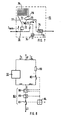
- FIG. 4 the variable high current resistor 10 with the Layer 11 and electrodes 12 and 13 in an insulating housing 30 introduced. It means 31 an insulating plate on the upper electrode 13, 32 a piezoelectric Actuator as a piezo elongator, 33 a leaf spring for generating contact force with associated support element 34 and set screws 35.
- the active elements are similar to those in FIG on the high current resistor 10; i.e. over the insulating plate 31, the piezo elongator 32 is arranged supported against the housing via the leaf spring 33 is.
- the electrical supply is not shown in FIG. 4.
- the piezo elongator 32 uses the so-called piezoelectric cross effect, i.e. he shortens his Length when a voltage of about 1 kV is applied about 0.5 to 1%.
- the change in the resistance value of the High current resistance takes place by controlling the Piezo elongators 32 with a sufficiently high voltage.
- the contact force in the boundary layers or Transition zones of the resistance element reduced proportional to the shortening of the piezo elongator 32 according to the spring constant of the used Spring element 33. It can be determined, for example, that with a shortening of the piezo elongator 32 to 50 ⁇ m with a suitable spring constant the contact force decreases by about 1500 N to 500 N.
- the piezoelectrically operated high current resistor 4 is used in conjunction with a Current sensor 45, an evaluation and control module 44, and a high-voltage pulse device 43.
- the associated Circuit results from FIG 5.
- the current sensor 45 the instantaneous current in the circuit is detected and in the evaluation and control module 44 the instantaneous current, for example, with a preset one Current threshold compared. If the instantaneous current exceeds the preset current threshold generates a drive signal in the high-voltage pulse device 43 a high voltage pulse of several ms generated for the piezo elongator 32 according to FIG. 4. Reduced by shortening the piezo elongator 32 the contact force in the high current resistor, causing its resistance by up to three powers of ten increases. This limits the current in the circuit.
- piezo elongator instead of arranging the piezo elongator according to FIG 4 with leaf spring can also other power transmission systems with other spring arrangements with medium Spring constant.
- piezo elongators be that their center of mass during the pulse operation remains at rest, so that the used Power transmission elements during the pulse duration no counter force acting on the spring force is obtained. Rather, this counterforce can be in the seconds range of special plastic spacers be taken over, which with rapid loading react rigidly, but flow behavior under continuous load demonstrate. This allows an automatic tracking device which can be realized with material removal at the actual high current resistor 10 a non-positive Positioning of the piezo elongator 32 again manufactures.
- changeable high current resistors be particularly connected used with a circuit breaker.
- a circuit according to FIG 1b at which the changeable high current resistance Circuit breaker is electrically connected in series, the is triggered by the short-circuit current and the Circuit ultimately breaks.
- the short-circuit current rise is quickly limited and the amplitude of the breakdown current for the non-critical circuit breaker connected in series Values limited.
- the electrical protective elements connected in series in an insulating housing for example made of ceramic, integrated be, for the purpose of electrical insulation and the heat conduction the elements of an insulating liquid, for example oil, which can be surrounded the electrical power loss thermally to the housing wall derives.
- the outer electrodes 12 and 13, the soot and / or carbon-containing layers 11 and the intermediate electrodes are mechanically connected in series and through a contact force with predetermined Compressed pressure.
- To improve heat dissipation of the intermediate electrodes to the insulation and cooling liquid can partial areas of the intermediate electrodes be in contact with the liquid.
- To the Protective elements in the event of a short circuit against overload protect is a second current path with a resistor connected in parallel.
- This resistance can be are located outside the insulating housing; however he can also be integrated into the insulating housing in such a way that each of the intermediate electrodes in electrical contact with e.g. parallel resistor designed as a resistance band stands, with the contact points over Distribute the length of the resistance band evenly. This ensures that when one of the Protective elements of the electric current on the parallel switched resistor section commutates and the ongoing flow of current safely all protection elements triggers.
- FIG. 6 shows an electrical parallel connection of several protective elements for the application at higher rated currents without increasing the constructively required contact force shown.
- the insulating intermediate layers present in FIG. 6 61, 61 ' also through layers containing soot, corresponding to layers 11, 11 '.
- the protective elements are electrically parallel and mechanical for the contact pressure connected in series. This also prevents that the constructive structure, e.g. a plastic housing, supporting contact force to a mechanical Overload leads, or that the construction with increased Material and volume expenditure can be carried out got to.
- Insulated enclosures may make sense to be gas-tight Make encapsulation and a protective gas, for example Hydrogen or nitrogen to use as a filling.
- the gas pressure can be one or more Atmospheres. Due to the gas filling Parameters available with which the training of Arcs can be controlled. Besides, that is explosion safety guaranteed.
- An inventive one is usually changeable High current resistor with a switching element in Series connected. Instead of connecting in series with one Circuit breakers can be described as changeable Resistance also directly into a circuit breaker be integrated, as shown with reference to FIG 7.
- the dimensioning of the current limiting element is therefore no longer based on the nominal current range of the circuit breaker to be protected, but conditions for safe arcing commutation on the tracks and a rapid increase in resistance.
- the changeable high-current resistor according to the invention also with power semiconductors as switching elements be combined. This can be done by a suitable Dimensioning the high current resistor the forward current and the current heat pulse in the event of a short circuit be limited to the extent that the power semiconductor is not harmed. The high current resistor then replaces a semiconductor fuse.
- the changeable high current resistor according to the invention can also be used in conjunction with shooters or Vacuum contactors can be switched as switching elements.
- shooters or Vacuum contactors can be switched as switching elements.
- by appropriate dimensioning the high-current resistor that a welding of the contacts of the contactor is avoided. This makes it sweat-free Protection of the contactor guaranteed.
- the changeable high current resistor described above can be in its sensitivity increase by the fact that in nominal current operation only a partial current flows through the high current resistor, while the other partial flow via a parallel flow branch to be led. Suitable switching means the parallel current branch switched on or off become. The latter is clear from FIG.
- FIG. 8 shows a circuit breaker contact 80 - corresponding to switch 1 in FIG. 1a - with a switch lock 84 and thermal and magnetic releases 85 and 86, to which a current path from two parallel current branches with partial currents I 1 and I 2 is electrically connected in series.
- the one parallel current branch contains the variable high current resistor 10 and the other parallel current branch contains a commutation contact 82 to which a constant resistor 83 is connected in series.
- the resistance value of the constant resistor 83 can be dimensioned such that it corresponds approximately to the low-resistance value of the variable high-current resistor 10, so that the current I is divided into approximately equal partial currents I 1 and I 2 of the parallel current branches. It is advantageous here that the electrical power loss of the parallel current paths is approximately half as large as a single current path with a variable high current resistor 10.
- the magnetic release 86 the circuit breaker 80, responds, the switching lock 84 is released, and the switching contacts 81 and 82 open when there is sufficient magnetic excitation.
- the arc voltage of the switch commutates the current I2 to the still low-resistance parallel branch.
- the power loss ( ⁇ I 2 ) in the changeable high-current resistor 10 is increased by a factor of 4, which leads to a rapid rise in temperature at the contact surface of the resistance element and reduces the effective contact force by compressive forces due to decomposition of the binder.
- the current limiting device can be set to be insensitive in rated operation and sensitive in the event of a short circuit.
Landscapes
- Engineering & Computer Science (AREA)
- Power Engineering (AREA)
- Microelectronics & Electronic Packaging (AREA)
- Thermistors And Varistors (AREA)
- Emergency Protection Circuit Devices (AREA)
- Adjustable Resistors (AREA)
- Electronic Switches (AREA)
Description
- FIG 1a and 1b
- zwei Schattungsanordnungen des Standes der Technik,
- FIG 2
- im Querschnitt einen Hochstromwiderstand mit ersten Mitteln zur Druckgenerierung zwecks Kraftverminderung mit zwei Funktionsausschnitten,
- FIG 3
- eine elektromagnetisch gesteuerte Anordnung als zweites Mittel zur Kraftverminderung,
- FIG 4
- eine über einen piezoelektrischen Stellgeber gesteuerte Anordnung als drittes Mittel zur Kraftverminderung,
- FIG 5
- die zur Aktivierung der Anordnung nach FIG 4 notwendige Schaltungsanordnung,
- FIG 6
- einen aus mehreren Schichten gestapelten Hochstromwiderstand,
- FIG 7
- einen in einen Leistungsschalter integrierten Hochstromwiderstand und
- FIG 8
- eine Schaltungsmodifikation des Hochstromwiderstandes zur Erhöhung der Empfindlichkeit.
- Die Stromwärme, die erforderlich ist, um die Oberfläche der Polymerschicht auf die kritische Temperatur aufzuheizen, ist proportional dem Temperaturhub von der Ausgangstemperatur bis zur kritischen Temperatur. Dies bedeutet im einzelnen, daß sich bei niedrigeren Ausgangstemperaturen schlechtere Schutzwerte als bei hohen Ausgangstemperaturen ergeben.
- Thermoplastkaltleiter können sich im Lauf einer langjährigen Betriebsdauer unter dem hohen Anpreßdruck der Elektroden, insbesondere bei erhöhten Temperaturen, verformen und damit ihre Ansprecheigenschaften ändern.
- Der Kaltleitereffekt und damit der Widerstandshub bei Erwärmung auf Temperaturen oberhalb der kritischen Temperatur hängt empfindlich vom Gefüge des Polymers ab. Nach einer Schaltung oder längerer Standzeit ohne Belastung kann sich der Widerstandshub wesentlich ändern, wodurch der Schutzeffekt in seiner Größe nicht in allen Fällen vorhersagbar ist.
Claims (31)
- Veränderbarer Hochstromwiderstand, insbesondere zur Anwendung als Schutzelement in der Leistungsschalttechnik, mit zumindest Kohlenstoff (101) und einem Bindemittel (102) als Widerstandsmaterial, wobei wenigstens eine Grenzfläche einer kohle- und/oder rußhaltigen Schicht (11) mit einer Übergangszone (15) zu einem weiteren elektrischen Leiter (12, 13), insbesondere einer Elektrode, vorhanden ist, die von einer Anpreßkraft beaufschlagt wird, und wobei die kohle- und/oder rußhaltige Schicht (11) zur Einstellung eines niederohmigen Zustandes des Widerstandes durch die Kraft mit vorgegebenem erstem Wert auf den weiteren elektrischen Leiter (12, 13), insbesondere auf die Elektrode, gepreßt wird, dadurch gekennzeichnet, daß Mittel zur gezielten Beeinflussung der Anpreßkraft vorhanden sind, womit im Kurzschlußfall die Anpreßkraft in hinreichend kurzer Zeit auf einen solchen zweiten Wert verminderbar ist, bei dem der Widerstand in der Übergangszone (15) um wenigstens zwei Größenordnungen ansteigt, wobei die Verminderung der Kraft bei hinreichend großem Strom durch Druckentwicklung zwischen der kohle- und/oder rußhaltigen Schicht (11) und dem weiteren elektrischen Leiter (12, 13), insbesondere der Elektrode, erfolgt, und wobei die Druckentwicklung zur Verminderung der Kraft überwiegend durch thermische Zersetzung des Bindemittels (102) in gasförmige Zersetzungsprodukte erfolgt, indem die Temperatur des Bindemittels in der Übergangszone der kohle- und/oder rußhaltigen Schicht (11) zum weiteren elektrischen Leiter (12, 13), insbesondere der benachbarten Elektrode, durch die elektrische Verlustleistung bis zur Zersetzungstemperatur erhöht wird.
- Veränderbarer Hochstromwiderstand nach Anspruch 1, gekennzeichnet durch zusätzliche Mittel (102, 21 bis 26, 31 bis 34) zur Verminderung der Kraft entsprechend dem fließenden Strom.
- Veränderbarer Hochstromwiderstand nach Anspruch 1 und 2, dadurch gekennzeichnet, daß zur Ausbildung als Schutzelement im Kurzschlußfall bei Überschreiten einer vorgebbaren Stromschwelle, beispielsweise dem 15fachen von Inenn, in einer Zeitdauer, die gegenüber der Netzperiode klein ist, der Widerstand in der Übergangszone (15) auf etwa das 100- bis 1000fache ansteigt und somit den Kurzschlußstrom auf ungefährliche Werte begrenzt.
- Veränderbarer Hochstromwiderstand nach Anspruch 1, dadurch gekennzeichnet, daß die Übergangszone (15) von zwei ruß- und/oder kohlehaltigen Schichten begrenzt wird.
- Veränderbarer Hochstromwiderstand nach Anspruch 1, dadurch gekennzeichnet, daß die Übergangszone (15) von wenigstens einer metallischen Elektrode (12, 13) und der ruß- und/oder kohlehaltigen Schicht (11) begrenzt wird.
- Veränderbarer Hochstromwiderstand nach Anspruch 1, dadurch gekennzeichnet, daß die kohle- und/oder rußhaltige Schicht (11) mit einer Stärke von wenigstens 100 um, vorzugsweise 1 mm, zwischen zwei metallische Elektroden (12, 13) eingepreßt ist.
- Veränderbarer Hochstromwiderstand nach Anspruch 5 und Anspruch 6, dadurch gekennzeichnet, daß die Oberfläche wenigstens einer der metallischen Elektroden strukturiert ist.
- Veränderbarer Hochstromwiderstand nach Anspruch 7, dadurch gekennzeichnet, daß die kohle- und/oder rußhaltige Schicht (11) eine zur Strukturierung komplementäre Struktur besitzt und daß Kräfte übertragen werden.
- Veränderbarer Hochstromwiderstand nach Anspruch 6, dadurch gekennzeichnet, daß die kohle- und/oder rußhaltige Schicht (11) wenigstens teilweise durch Kohlefasern in papier-, folien- oder filzartiger Konsistenz gebildet ist.
- Veränderbarer Hochstromwiderstand nach Anspruch 1, dadurch gekennzeichnet, daß die kohle- und/oder rußhaltige Schicht (11) Bindemittel (102) aufweist.
- Veränderbarer Hochstromwiderstand nach Anspruch 10, dadurch gekennzeichnet, daß das Bindemittel (102) Polymerwerkstoffe, beispielsweise Polyethylen, Polyester od. dgl., oder Wachse, Fette, Teere oder Peche ist.
- Veränderbarer Hochstromwiderstandes nach Anspruch 10, dadurch gekennzeichnet, daß die Herstellung der Schicht (11) aus ruß- und feinkörnigem Kohlepulver (101) durch Zusatz von Teer und Pech als Bindemittel (102) und Verpressen der Schicht bei niedrigem Druck erfolgt ist, so daß nach Glühen der Schicht bei Temperaturen bis zu 1000°C eine elektrisch leitfähige poröse Schicht vorliegt.
- Veränderbarer Hochstromwiderstand nach Anspruch 10, dadurch gekennzeichnet, daß ein Bindemittel (102) verwendet wird, das oberhalb vorgegebener Temperaturen in Zersetzungsprodukte zerfällt.
- Veränderbarer Hochstromwiderstand nach Anspruch 1, dadurch gekennzeichnet, daß in der Übergangszone (15) die elektrische Verlustleistung das Bindemittel (102) zwischen den Kohle- und/ oder Rußpartikeln in gasförmige Zersetzungsprodukte (103) aufspaltet und die Zersetzungsgase eine Druckkraft erzeugen, die der Anpreßkraft entgegengesetzt ist.
- Veränderbarer Hochstromwiderstand nach Anspruch 1 und 12, dadurch gekennzeichnet, daß zur Herstellung der Schicht (11) der geglühte Preßkörper mit Wachs oder Fetten getränkt wird, die bei Temperaturen oberhalb von 200°C in die gasförmigen Zersetzungsprodukte (103) zur Erzeugung des Druckes zerfallen.
- Veränderbarer Hochstromwiderstand nach Anspruch 2, dadurch gekennzeichnet, daß als zusätzlich Mittel zur Verminderung der Kraft entsprechend dem fließenden Strom ein Elektromagnet (22 bis 24) vorhanden ist.
- Veränderbarer Hochstromwiderstand nach Anspruch 16, dadurch gekennzeichnet, daß eine elektromagnetische Kraft zwischen Joch (22) und Anker (23) des Elektromagneten, der durch den Kurzschlußstrom selbst erregt wird, erzeugt wird.
- Veränderbarer Hochstromwiderstand nach Anspruch 2, dadurch gekennzeichnet, daß als zusätzliche Mittel zur Verminderung der Kraft elektrische Aktoren (32), beispielsweise ein piezoelektrisches Stellelement zur Erzeugung hoher Kräfte bei kleinen Wegen, vorhanden sind.
- Veränderbarer Hochstromwiderstand nach Anspruch 18, dadurch gekennzeichnet, daß mittels eines separaten Steuerkreises (43 bis 45), der beispielsweise bei Überschreiten einer einstellbaren Stromschwelle das piezoelektrische Stellelement ansteuert, vom als Elongator (32) ausgebildeten Stellelement die Kraft zwischen der Übergangszone (15) vermindert wird, so daß der Widerstand (10) hochohmig wird.
- Veränderbarer Hochstromwiderstand nach Anspruch 1 oder einem der Ansprüche 16 bis 19, gekennzeichnet durch eine Kapselung in einem Isoliergehäuse (20, 30) unter Schutzgas, beispielsweise Wasserstoff oder Stickstoff.
- Veränderbarer Hochstromwiderstand nach einem der vorhergehenden Ansprüche, gekennzeichnet durch einen Schichtaufbau (60), wobei mehrere kohle- und/oder rußhaltige Schichten (11, 11', 11") mechanisch hintereinander, elektrisch aber parallel geschaltet sind.
- Veränderbarer Hochstromwiderstand nach einem der vorhergehenden Ansprüche, dadurch gekennzeichnet, daß zur Erhöhung der Kurzschluß-Ansprechempfindlichkeit Mittel (82,83) zur Kommutierung eines Teilstromes (I1) von einem Parallelstromzweig auf den Hochstromwiderstand (10) vorhanden sind.
- Schaltung unter Verwendung eines veränderbaren Hochstromwiderstandes nach Anspruch 1 oder einem der Ansprüche 2 bis 22, gekennzeichnet durch die Serienschaltung mehrerer Hochstromwiderstände (10) als Schutzelemente zur Strombegrenzung, so daß bei Ansprechen aller in Serie geschalteten Elemente eine Spannung von mehreren 1000 V erreicht wird, wodurch die Strombegrenzung auch im Mittelspannungsbereich von über 1000 V erfolgt.
- Schaltung nach Anspruch 23, dadurch gekennzeichnet, daß mehrere Hochstromwiderstände (10) als Schutzelemente in einem gemeinsamen Isoliergehäuse mit Isolier- und Kühlflüssigkeit angeordnet sind und daß ein äußerer Parallelwiderstand vorhanden ist.
- Schaltung nach Anspruch 24, dadurch gekennzeichnet, daß mehrere Hochstromwiderstände (10) als Schutzelemente in einem gemeinsamen Isoliergehäuse mit Isolier- und Kühlflüssigkeit angeordnet sind und daß Parallelwiderstände mit Kontaktstellen zu den einzelnen Schutzelementen vorhanden sind.
- Schaltung unter Verwendung eines veränderbaren Hochstromwiderstandes nach Anspruch 1 oder einem der Ansprüche 2 bis 23, mit einem Leistungsschalter als Schaltelement, dadurch gekennzeichnet, daß der Hochstromwiderstand (10) und der Leistungsschalter (7) in einem gemeinsamen Gehäuse (70) integriert sind.
- Schaltung nach Anspruch 26, dadurch gekennzeichnet, daß der veränderbare Hochstromwiderstand (10) in einem Nebenstrompfad zur Kontaktstelle des Leistungsschalters (71) angeordnet ist.
- Schaltung nach Anspruch 27, dadurch gekennzeichnet, daß der veränderbare Hochstromwiderstand (10) im Kurzschlußfall erst dann vom Strom durchflossen wird, wenn die Stromkontakte (72, 73) geöffnet sind und ein Lichtbogen auf wenigstens eine der Lichtbogenlaufschienen (77, 78) kommutiert ist.
- Schaltung unter Verwendung eines steuerbaren Hochstromwiderstandes nach Anspruch 1 oder einem der Ansprüche 2 bis 23, mit einem Leistungshalbleiter als Schaltelement, dadurch gekennzeichnet, daß durch geeignete Dimensionierung des Hochstromwiderstandes (10) der Durchlaßstrom und der Stromwärmeimpuls (I2T-Wert) im Kurzschlußfall soweit begrenzt werden, daß der Leistungshalbleiter nicht geschädigt wird.
- Schaltung unter Verwendung eines steuerbaren Hochstromwiderstandes nach Anspruch 1 oder einem der Ansprüche 2 bis 23, mit einem Schütz als Schaltelement, dadurch gekennzeichnet, daß durch geeignete Dimensionierung des Hochstrom-widerstandes (10) der Durchlaßstrom und der Stromwärmeimpuls im Kurzschlußfall soweit begrenzt werden, daß ein Verschweißen der Kontakte des Schützes vermieden wird.
- Schaltung unter Verwendung eines veränderbaren Hochstromwiderstandes nach Anspruch 1 oder einem der Ansprüche 2 bis 23, mit einem Vakuumschütz als Schaltelement, dadurch gekennzeichnet, daß durch geeignete Dimensionierung des Hochstromwiderstandes (10) das Vakuumschütz nicht durch Überlastung geschädigt wird.
Applications Claiming Priority (3)
| Application Number | Priority Date | Filing Date | Title |
|---|---|---|---|
| DE4228297 | 1992-08-26 | ||
| DE4228297A DE4228297A1 (de) | 1992-08-26 | 1992-08-26 | Veränderbarer Hochstromwiderstand, insbes. zur Anwendung als Schutzelement in der Leistungsschalttechnik, und Schaltung unter Verwendung des Hochstromwiderstandes |
| PCT/DE1993/000721 WO1994006130A1 (de) | 1992-08-26 | 1993-08-11 | Veränderbarer hochstromwiderstand und anwendung als schutzelement |
Publications (3)
| Publication Number | Publication Date |
|---|---|
| EP0657062A1 EP0657062A1 (de) | 1995-06-14 |
| EP0657062B1 EP0657062B1 (de) | 1997-03-19 |
| EP0657062B2 true EP0657062B2 (de) | 2002-03-27 |
Family
ID=6466429
Family Applications (1)
| Application Number | Title | Priority Date | Filing Date |
|---|---|---|---|
| EP93917545A Expired - Lifetime EP0657062B2 (de) | 1992-08-26 | 1993-08-11 | Veränderbarer hochstromwiderstand und anwendung als schutzelement |
Country Status (7)
| Country | Link |
|---|---|
| US (1) | US5644283A (de) |
| EP (1) | EP0657062B2 (de) |
| JP (1) | JP3499240B2 (de) |
| AT (1) | ATE150580T1 (de) |
| DE (2) | DE4228297A1 (de) |
| ES (1) | ES2099462T5 (de) |
| WO (1) | WO1994006130A1 (de) |
Families Citing this family (59)
| Publication number | Priority date | Publication date | Assignee | Title |
|---|---|---|---|---|
| DE4330607A1 (de) * | 1993-09-09 | 1995-03-16 | Siemens Ag | Limiter zur Strombegrenzung |
| FR2733353B1 (fr) * | 1995-04-18 | 1997-05-16 | Gec Alsthom T & D Sa | Limiteur de courant de court-circuit pour reseau a haute tension |
| DE19803919A1 (de) * | 1997-02-10 | 1998-08-13 | Gen Electric | Stromunterdrückungs- Schaltereinheit für Induktionsmotorschutz |
| US5929744A (en) * | 1997-02-18 | 1999-07-27 | General Electric Company | Current limiting device with at least one flexible electrode |
| US6535103B1 (en) | 1997-03-04 | 2003-03-18 | General Electric Company | Current limiting arrangement and method |
| US5977861A (en) * | 1997-03-05 | 1999-11-02 | General Electric Company | Current limiting device with grooved electrode structure |
| SE509270C2 (sv) * | 1997-04-14 | 1998-12-21 | Asea Brown Boveri | Variabelt elektriskt motstånd samt förfarande för att öka respektive ändra resistansen hos ett elektriskt motstånd |
| CN1135570C (zh) * | 1997-06-04 | 2004-01-21 | 泰科电子有限公司 | 电路保护器件 |
| US6191681B1 (en) | 1997-07-21 | 2001-02-20 | General Electric Company | Current limiting device with electrically conductive composite and method of manufacturing the electrically conductive composite |
| US6373372B1 (en) * | 1997-11-24 | 2002-04-16 | General Electric Company | Current limiting device with conductive composite material and method of manufacturing the conductive composite material and the current limiting device |
| US6128168A (en) | 1998-01-14 | 2000-10-03 | General Electric Company | Circuit breaker with improved arc interruption function |
| DE19810982A1 (de) * | 1998-03-13 | 1999-09-16 | Abb Research Ltd | Strombegrenzer und Schnellerder mit leitfähigem Pulver |
| US6124780A (en) * | 1998-05-20 | 2000-09-26 | General Electric Company | Current limiting device and materials for a current limiting device |
| US6290879B1 (en) | 1998-05-20 | 2001-09-18 | General Electric Company | Current limiting device and materials for a current limiting device |
| US6430019B1 (en) | 1998-06-08 | 2002-08-06 | Ferraz S.A. | Circuit protection device |
| US6040971A (en) * | 1998-06-08 | 2000-03-21 | Martenson; Kenneth R. | Circuit protection device |
| US6133820A (en) * | 1998-08-12 | 2000-10-17 | General Electric Company | Current limiting device having a web structure |
| US6144540A (en) | 1999-03-09 | 2000-11-07 | General Electric Company | Current suppressing circuit breaker unit for inductive motor protection |
| US6157286A (en) | 1999-04-05 | 2000-12-05 | General Electric Company | High voltage current limiting device |
| US6404323B1 (en) * | 1999-05-25 | 2002-06-11 | Varatouch Technology Incorporated | Variable resistance devices and methods |
| US7190251B2 (en) | 1999-05-25 | 2007-03-13 | Varatouch Technology Incorporated | Variable resistance devices and methods |
| US6323751B1 (en) | 1999-11-19 | 2001-11-27 | General Electric Company | Current limiter device with an electrically conductive composite material and method of manufacturing |
| US6560085B1 (en) * | 1999-12-20 | 2003-05-06 | Square D Company | Circuit breaker including positive temperature coefficient resistivity element and current limiting element |
| US6388553B1 (en) * | 2000-03-02 | 2002-05-14 | Eaton Corproation | Conductive polymer current-limiting fuse |
| US6411191B1 (en) | 2000-10-24 | 2002-06-25 | Eaton Corporation | Current-limiting device employing a non-uniform pressure distribution between one or more electrodes and a current-limiting material |
| EP1213728A3 (de) * | 2000-11-27 | 2005-10-26 | Eaton Corporation | Strombegrenzungseinrichtung |
| US6798331B2 (en) * | 2001-02-08 | 2004-09-28 | Qortek, Inc. | Current control device |
| DE10118746B4 (de) * | 2001-04-17 | 2004-06-24 | Siemens Ag | Verfahren zum Betreiben eines Schaltgerätes mit einem zuschaltbaren Strombegrenzer und zugehörige Anordnung |
| US6958671B2 (en) * | 2001-11-15 | 2005-10-25 | Square D Company | Electrical contactor with positive temperature coefficient resistivity element |
| US7474772B2 (en) * | 2003-06-25 | 2009-01-06 | Atrua Technologies, Inc. | System and method for a miniature user input device |
| US7587072B2 (en) | 2003-08-22 | 2009-09-08 | Authentec, Inc. | System for and method of generating rotational inputs |
| EP1714271A2 (de) * | 2004-02-12 | 2006-10-25 | Atrua Technologies, Inc. | System und verfahren zum emulieren von mausoperationen unter verwendung von fingerbildsensoren |
| KR100794722B1 (ko) * | 2005-02-05 | 2008-01-21 | 박승혁 | 접촉눌림에 의한 변위감응센서 |
| JP2006310512A (ja) * | 2005-04-28 | 2006-11-09 | Sanyo Electric Co Ltd | 化合物半導体スイッチ回路装置 |
| US20070061126A1 (en) * | 2005-09-01 | 2007-03-15 | Anthony Russo | System for and method of emulating electronic input devices |
| DE102005046118A1 (de) * | 2005-09-27 | 2007-03-29 | Robert Bosch Gmbh | Piezoaktor mit Schutzwiderstand |
| JP2007103526A (ja) * | 2005-09-30 | 2007-04-19 | Tdk Corp | サーミスタ |
| WO2007097979A2 (en) * | 2006-02-10 | 2007-08-30 | Atrua Technologies, Inc. | Systems using variable resistance zones and stops for generating inputs to an electronic device |
| US9235274B1 (en) | 2006-07-25 | 2016-01-12 | Apple Inc. | Low-profile or ultra-thin navigation pointing or haptic feedback device |
| US7483252B2 (en) * | 2006-12-05 | 2009-01-27 | Ferraz Shawmut S.A. | Circuit protection device |
| KR100794724B1 (ko) * | 2007-10-12 | 2008-01-21 | 박승혁 | 접촉눌림에 의한 변위감응센서 |
| KR100794726B1 (ko) * | 2007-10-12 | 2008-01-21 | 박승혁 | 접촉눌림에 의한 변위감응센서 |
| KR100794725B1 (ko) * | 2007-10-12 | 2008-01-21 | 박승혁 | 접촉눌림에 의한 변위감응센서 |
| KR100794723B1 (ko) * | 2007-10-12 | 2008-01-21 | 박승혁 | 접촉눌림에 의한 변위감응센서 |
| US8866347B2 (en) | 2010-01-15 | 2014-10-21 | Idex Asa | Biometric image sensing |
| US8421890B2 (en) | 2010-01-15 | 2013-04-16 | Picofield Technologies, Inc. | Electronic imager using an impedance sensor grid array and method of making |
| US8791792B2 (en) | 2010-01-15 | 2014-07-29 | Idex Asa | Electronic imager using an impedance sensor grid array mounted on or about a switch and method of making |
| DE102011013334A1 (de) * | 2011-03-08 | 2012-09-13 | Epcos Ag | Elektrisches Modul zur Einschaltstrombegrenzung |
| US8810988B2 (en) | 2011-11-04 | 2014-08-19 | Mersen Usa Newburyport-Ma, Llc | Circuit protection device |
| US8477468B2 (en) | 2011-11-04 | 2013-07-02 | Mersen Usa Newburyport-Ma, Llc | Circuit protection device |
| WO2013155224A1 (en) | 2012-04-10 | 2013-10-17 | Picofield Technologies Inc. | Biometric sensing |
| DE102013101835A1 (de) * | 2013-02-25 | 2014-08-28 | Haake Technik Gmbh | Zweikanaliger, mehrlagiger taktiler Sensor |
| US9619990B2 (en) * | 2013-09-06 | 2017-04-11 | Junior Dunn | Smart output protector |
| KR101897725B1 (ko) * | 2014-04-08 | 2018-09-12 | 지멘스 악티엔게젤샤프트 | 과전류 손상으로부터 전기적 모듈러 유닛을 보호하기 위한 방법 |
| DE102017207713A1 (de) * | 2017-05-08 | 2018-11-08 | Robert Bosch Gmbh | Shunt-Widerstand zur Zustandserkennung einer elektrischen Energiespeichereinheit |
| FR3067870B1 (fr) * | 2017-06-16 | 2021-01-01 | Schneider Electric Ind Sas | Appareil de protection electrique comportant un dispositif limiteur de courant |
| US11488798B2 (en) | 2020-03-17 | 2022-11-01 | Hamilton Sundstrand Corporation | Current source contactor drive with economizers |
| DE102020213107A1 (de) | 2020-10-16 | 2022-04-21 | Robert Bosch Gesellschaft mit beschränkter Haftung | Schaltvorrichtung, elektrischer Energiespeicher und Vorrichtung |
| LU502264B1 (en) * | 2022-06-14 | 2023-12-14 | Helion Energy Inc | High-Energy Particulate Resistors |
Family Cites Families (17)
| Publication number | Priority date | Publication date | Assignee | Title |
|---|---|---|---|---|
| DE272807C (de) * | ||||
| US2951817A (en) * | 1959-07-28 | 1960-09-06 | Thomas E Myers | Variable resistance material |
| US3138686A (en) * | 1961-02-01 | 1964-06-23 | Gen Electric | Thermal switch device |
| US3243753A (en) * | 1962-11-13 | 1966-03-29 | Kohler Fred | Resistance element |
| US3386067A (en) * | 1967-04-24 | 1968-05-28 | Raphael J. Costanzo | Pressure-sensitive electrical switch and application therefor |
| US3806471A (en) * | 1968-04-29 | 1974-04-23 | R Mitchell | Pressure responsive resistive material |
| US3626348A (en) * | 1969-04-02 | 1971-12-07 | Essex International Inc | Current-regulating apparatus |
| US4101862A (en) * | 1976-11-19 | 1978-07-18 | K.K. Tokai Rika Denki Seisakusho | Current limiting element for preventing electrical overcurrent |
| US4685025A (en) * | 1985-03-14 | 1987-08-04 | Raychem Corporation | Conductive polymer circuit protection devices having improved electrodes |
| US4639818A (en) * | 1985-09-17 | 1987-01-27 | Raychem Corporation | Vent hole assembly |
| US4745301A (en) * | 1985-12-13 | 1988-05-17 | Advanced Micro-Matrix, Inc. | Pressure sensitive electro-conductive materials |
| JPH01225031A (ja) * | 1988-03-02 | 1989-09-07 | Yaskawa Electric Mfg Co Ltd | 事故電流限流装置 |
| US4967176A (en) * | 1988-07-15 | 1990-10-30 | Raychem Corporation | Assemblies of PTC circuit protection devices |
| JPH0741122Y2 (ja) * | 1989-11-28 | 1995-09-20 | 林原 健 | 密閉型可変抵抗器 |
| SE465524B (sv) * | 1990-02-08 | 1991-09-23 | Asea Brown Boveri | Anordning foer oeverlast- och kortslutningsskydd i elektriska anlaeggningar |
| JPH047801A (ja) * | 1990-04-25 | 1992-01-13 | Daito Tsushinki Kk | Ptc素子 |
| US5382938A (en) * | 1990-10-30 | 1995-01-17 | Asea Brown Boveri Ab | PTC element |
-
1992
- 1992-08-26 DE DE4228297A patent/DE4228297A1/de not_active Withdrawn
-
1993
- 1993-08-11 AT AT93917545T patent/ATE150580T1/de not_active IP Right Cessation
- 1993-08-11 JP JP50673394A patent/JP3499240B2/ja not_active Expired - Fee Related
- 1993-08-11 EP EP93917545A patent/EP0657062B2/de not_active Expired - Lifetime
- 1993-08-11 US US08/381,927 patent/US5644283A/en not_active Expired - Fee Related
- 1993-08-11 DE DE59305896T patent/DE59305896D1/de not_active Expired - Fee Related
- 1993-08-11 WO PCT/DE1993/000721 patent/WO1994006130A1/de not_active Ceased
- 1993-08-11 ES ES93917545T patent/ES2099462T5/es not_active Expired - Lifetime
Also Published As
| Publication number | Publication date |
|---|---|
| JPH08500703A (ja) | 1996-01-23 |
| EP0657062A1 (de) | 1995-06-14 |
| ES2099462T5 (es) | 2002-11-16 |
| US5644283A (en) | 1997-07-01 |
| ATE150580T1 (de) | 1997-04-15 |
| EP0657062B1 (de) | 1997-03-19 |
| JP3499240B2 (ja) | 2004-02-23 |
| WO1994006130A1 (de) | 1994-03-17 |
| DE4228297A1 (de) | 1994-03-03 |
| DE59305896D1 (de) | 1997-04-24 |
| ES2099462T3 (es) | 1997-05-16 |
Similar Documents
| Publication | Publication Date | Title |
|---|---|---|
| EP0657062B1 (de) | Veränderbarer hochstromwiderstand und anwendung als schutzelement | |
| DE68922733T2 (de) | Ptc-schaltungsschutzanordnungen. | |
| EP0713227B1 (de) | Kaltleiter und Vorrichtung zur Strombegrenzung mit mindestens einem Kaltleiter | |
| DE4441279C1 (de) | Vorrichtung zur Strombegrenzung | |
| DE202006020737U1 (de) | Passive oder aktive Kurzschließeinrichtung für den Einsatz in Nieder- und Mittelspannungsanlagen zum Sach- und Personenschutz | |
| EP0829101A1 (de) | RESISTIVE STROMBEGRENZUNGSEINRICHTUNG UNTER VERWENDUNG VON HOCH-Tc-SUPRALEITERMATERIAL | |
| EP0717876B1 (de) | Limiter zur strombegrenzung | |
| DE102012112487A1 (de) | Temperaturschutzschaltung | |
| DE102022111392A1 (de) | Hybridschutzschaltervorrichtung, Hybridschütz und Verfahren | |
| DE7507461U (de) | Kaltleiter-bauelement | |
| EP0913018B1 (de) | Supraleitender kurzschlussstrombegrenzer | |
| EP0750788B1 (de) | Schalter zur strombegrenzung | |
| EP1384240B1 (de) | Verfahren zum betreiben eines schaltgerätes mit einem zuschaltbaren strombegrenzer und zugehörige anordnung | |
| EP4199026B1 (de) | Schutzschalter | |
| WO1999017415A1 (de) | Leistungsschaltereinrichtung zur energieversorgung und -verteilung | |
| DE623439C (de) | ||
| EP1644952A1 (de) | Verfahren und vorrichtung zur strombegrenzung mit einem selbstbetätigten strombegrenzer | |
| DE602004008957T2 (de) | Elektromagnetisch verbesserter stromunterbrecher | |
| EP2859561A1 (de) | Kontaktelement für einen varistor | |
| DE102021214610B3 (de) | Schutzschalter und Kraftfahrzeug mit einem solchen Schutzschalter | |
| DE2905747A1 (de) | Strombegrenzungseinrichtung fuer hochspannungsschaltanlagen | |
| EP4199019A1 (de) | Schutzschalter | |
| EP3953957B1 (de) | Verfahren zur unterbrechungsfreien anpassung von parametern eines stromkreises | |
| WO1999025050A1 (de) | Strombegrenzereinrichtung für schaltnetze | |
| DE19534442A1 (de) | Überstromschutzvorrichtung |
Legal Events
| Date | Code | Title | Description |
|---|---|---|---|
| PUAI | Public reference made under article 153(3) epc to a published international application that has entered the european phase |
Free format text: ORIGINAL CODE: 0009012 |
|
| 17P | Request for examination filed |
Effective date: 19950119 |
|
| AK | Designated contracting states |
Kind code of ref document: A1 Designated state(s): AT CH DE ES FR GB LI SE |
|
| GRAG | Despatch of communication of intention to grant |
Free format text: ORIGINAL CODE: EPIDOS AGRA |
|
| GRAH | Despatch of communication of intention to grant a patent |
Free format text: ORIGINAL CODE: EPIDOS IGRA |
|
| 17Q | First examination report despatched |
Effective date: 19960801 |
|
| GRAH | Despatch of communication of intention to grant a patent |
Free format text: ORIGINAL CODE: EPIDOS IGRA |
|
| GRAH | Despatch of communication of intention to grant a patent |
Free format text: ORIGINAL CODE: EPIDOS IGRA |
|
| GRAA | (expected) grant |
Free format text: ORIGINAL CODE: 0009210 |
|
| AK | Designated contracting states |
Kind code of ref document: B1 Designated state(s): AT CH DE ES FR GB LI SE |
|
| REF | Corresponds to: |
Ref document number: 150580 Country of ref document: AT Date of ref document: 19970415 Kind code of ref document: T |
|
| REG | Reference to a national code |
Ref country code: CH Ref legal event code: NV Representative=s name: SIEMENS SCHWEIZ AG Ref country code: CH Ref legal event code: EP |
|
| REF | Corresponds to: |
Ref document number: 59305896 Country of ref document: DE Date of ref document: 19970424 |
|
| GBT | Gb: translation of ep patent filed (gb section 77(6)(a)/1977) |
Effective date: 19970414 |
|
| REG | Reference to a national code |
Ref country code: ES Ref legal event code: FG2A Ref document number: 2099462 Country of ref document: ES Kind code of ref document: T3 |
|
| ET | Fr: translation filed | ||
| PLBQ | Unpublished change to opponent data |
Free format text: ORIGINAL CODE: EPIDOS OPPO |
|
| PLBI | Opposition filed |
Free format text: ORIGINAL CODE: 0009260 |
|
| PLBF | Reply of patent proprietor to notice(s) of opposition |
Free format text: ORIGINAL CODE: EPIDOS OBSO |
|
| 26 | Opposition filed |
Opponent name: ASEA BROWN BOVERI AB Effective date: 19971218 |
|
| PLBF | Reply of patent proprietor to notice(s) of opposition |
Free format text: ORIGINAL CODE: EPIDOS OBSO |
|
| PLBF | Reply of patent proprietor to notice(s) of opposition |
Free format text: ORIGINAL CODE: EPIDOS OBSO |
|
| PLAW | Interlocutory decision in opposition |
Free format text: ORIGINAL CODE: EPIDOS IDOP |
|
| PLAW | Interlocutory decision in opposition |
Free format text: ORIGINAL CODE: EPIDOS IDOP |
|
| REG | Reference to a national code |
Ref country code: GB Ref legal event code: IF02 |
|
| PUAH | Patent maintained in amended form |
Free format text: ORIGINAL CODE: 0009272 |
|
| STAA | Information on the status of an ep patent application or granted ep patent |
Free format text: STATUS: PATENT MAINTAINED AS AMENDED |
|
| 27A | Patent maintained in amended form |
Effective date: 20020327 |
|
| AK | Designated contracting states |
Kind code of ref document: B2 Designated state(s): AT CH DE ES FR GB LI SE |
|
| REG | Reference to a national code |
Ref country code: CH Ref legal event code: AEN Free format text: AUFRECHTERHALTUNG DES PATENTES IN GEAENDERTER FORM |
|
| GBTA | Gb: translation of amended ep patent filed (gb section 77(6)(b)/1977) | ||
| PGFP | Annual fee paid to national office [announced via postgrant information from national office to epo] |
Ref country code: ES Payment date: 20020829 Year of fee payment: 10 |
|
| ET3 | Fr: translation filed ** decision concerning opposition | ||
| ET3 | Fr: translation filed ** decision concerning opposition | ||
| REG | Reference to a national code |
Ref country code: ES Ref legal event code: DC2A Kind code of ref document: T5 Effective date: 20020627 |
|
| PGFP | Annual fee paid to national office [announced via postgrant information from national office to epo] |
Ref country code: AT Payment date: 20030723 Year of fee payment: 11 |
|
| PGFP | Annual fee paid to national office [announced via postgrant information from national office to epo] |
Ref country code: SE Payment date: 20030807 Year of fee payment: 11 Ref country code: GB Payment date: 20030807 Year of fee payment: 11 |
|
| PGFP | Annual fee paid to national office [announced via postgrant information from national office to epo] |
Ref country code: CH Payment date: 20031105 Year of fee payment: 11 |
|
| PG25 | Lapsed in a contracting state [announced via postgrant information from national office to epo] |
Ref country code: GB Free format text: LAPSE BECAUSE OF NON-PAYMENT OF DUE FEES Effective date: 20040811 Ref country code: AT Free format text: LAPSE BECAUSE OF NON-PAYMENT OF DUE FEES Effective date: 20040811 |
|
| PG25 | Lapsed in a contracting state [announced via postgrant information from national office to epo] |
Ref country code: SE Free format text: LAPSE BECAUSE OF NON-PAYMENT OF DUE FEES Effective date: 20040812 Ref country code: ES Free format text: LAPSE BECAUSE OF NON-PAYMENT OF DUE FEES Effective date: 20040812 |
|
| PG25 | Lapsed in a contracting state [announced via postgrant information from national office to epo] |
Ref country code: LI Free format text: LAPSE BECAUSE OF NON-PAYMENT OF DUE FEES Effective date: 20040831 Ref country code: CH Free format text: LAPSE BECAUSE OF NON-PAYMENT OF DUE FEES Effective date: 20040831 |
|
| EUG | Se: european patent has lapsed | ||
| GBPC | Gb: european patent ceased through non-payment of renewal fee |
Effective date: 20040811 |
|
| REG | Reference to a national code |
Ref country code: CH Ref legal event code: PL |
|
| REG | Reference to a national code |
Ref country code: ES Ref legal event code: FD2A Effective date: 20040812 |
|
| PGFP | Annual fee paid to national office [announced via postgrant information from national office to epo] |
Ref country code: DE Payment date: 20061023 Year of fee payment: 14 |
|
| PGFP | Annual fee paid to national office [announced via postgrant information from national office to epo] |
Ref country code: FR Payment date: 20070828 Year of fee payment: 15 |
|
| PG25 | Lapsed in a contracting state [announced via postgrant information from national office to epo] |
Ref country code: DE Free format text: LAPSE BECAUSE OF NON-PAYMENT OF DUE FEES Effective date: 20080301 |
|
| REG | Reference to a national code |
Ref country code: FR Ref legal event code: ST Effective date: 20090430 |
|
| PG25 | Lapsed in a contracting state [announced via postgrant information from national office to epo] |
Ref country code: FR Free format text: LAPSE BECAUSE OF NON-PAYMENT OF DUE FEES Effective date: 20080901 |