EP0655565B1 - Dispositifs et procédé d'amortissement de choc, ossature et véhicule comportant de tels dispositifs d'amortissement de choc - Google Patents
Dispositifs et procédé d'amortissement de choc, ossature et véhicule comportant de tels dispositifs d'amortissement de choc Download PDFInfo
- Publication number
- EP0655565B1 EP0655565B1 EP94400877A EP94400877A EP0655565B1 EP 0655565 B1 EP0655565 B1 EP 0655565B1 EP 94400877 A EP94400877 A EP 94400877A EP 94400877 A EP94400877 A EP 94400877A EP 0655565 B1 EP0655565 B1 EP 0655565B1
- Authority
- EP
- European Patent Office
- Prior art keywords
- chassis
- impact
- longitudinal
- central axis
- absorber
- Prior art date
- Legal status (The legal status is an assumption and is not a legal conclusion. Google has not performed a legal analysis and makes no representation as to the accuracy of the status listed.)
- Expired - Lifetime
Links
- 230000035939 shock Effects 0.000 title description 88
- 238000000034 method Methods 0.000 title description 2
- 239000006096 absorbing agent Substances 0.000 claims description 35
- 229910000831 Steel Inorganic materials 0.000 claims description 8
- 239000010959 steel Substances 0.000 claims description 8
- 230000008878 coupling Effects 0.000 claims description 7
- 238000010168 coupling process Methods 0.000 claims description 7
- 238000005859 coupling reaction Methods 0.000 claims description 7
- 230000002787 reinforcement Effects 0.000 claims description 5
- 238000010521 absorption reaction Methods 0.000 description 42
- 238000006073 displacement reaction Methods 0.000 description 11
- 238000013016 damping Methods 0.000 description 7
- 230000000694 effects Effects 0.000 description 6
- 238000003466 welding Methods 0.000 description 5
- 239000000463 material Substances 0.000 description 4
- 239000002184 metal Substances 0.000 description 3
- 230000001133 acceleration Effects 0.000 description 2
- 239000011324 bead Substances 0.000 description 2
- 230000005540 biological transmission Effects 0.000 description 2
- 230000000284 resting effect Effects 0.000 description 2
- 239000000872 buffer Substances 0.000 description 1
- 230000015556 catabolic process Effects 0.000 description 1
- 230000000295 complement effect Effects 0.000 description 1
- 230000006835 compression Effects 0.000 description 1
- 238000007906 compression Methods 0.000 description 1
- 239000004020 conductor Substances 0.000 description 1
- 238000006731 degradation reaction Methods 0.000 description 1
- 230000005489 elastic deformation Effects 0.000 description 1
- 238000009863 impact test Methods 0.000 description 1
- 210000000056 organ Anatomy 0.000 description 1
- 230000002441 reversible effect Effects 0.000 description 1
- 238000005096 rolling process Methods 0.000 description 1
- 230000011664 signaling Effects 0.000 description 1
Images








Classifications
-
- F—MECHANICAL ENGINEERING; LIGHTING; HEATING; WEAPONS; BLASTING
- F16—ENGINEERING ELEMENTS AND UNITS; GENERAL MEASURES FOR PRODUCING AND MAINTAINING EFFECTIVE FUNCTIONING OF MACHINES OR INSTALLATIONS; THERMAL INSULATION IN GENERAL
- F16F—SPRINGS; SHOCK-ABSORBERS; MEANS FOR DAMPING VIBRATION
- F16F7/00—Vibration-dampers; Shock-absorbers
- F16F7/12—Vibration-dampers; Shock-absorbers using plastic deformation of members
-
- B—PERFORMING OPERATIONS; TRANSPORTING
- B60—VEHICLES IN GENERAL
- B60R—VEHICLES, VEHICLE FITTINGS, OR VEHICLE PARTS, NOT OTHERWISE PROVIDED FOR
- B60R19/00—Wheel guards; Radiator guards, e.g. grilles; Obstruction removers; Fittings damping bouncing force in collisions
- B60R19/02—Bumpers, i.e. impact receiving or absorbing members for protecting vehicles or fending off blows from other vehicles or objects
- B60R19/18—Bumpers, i.e. impact receiving or absorbing members for protecting vehicles or fending off blows from other vehicles or objects characterised by the cross-section; Means within the bumper to absorb impact
-
- B—PERFORMING OPERATIONS; TRANSPORTING
- B61—RAILWAYS
- B61D—BODY DETAILS OR KINDS OF RAILWAY VEHICLES
- B61D15/00—Other railway vehicles, e.g. scaffold cars; Adaptations of vehicles for use on railways
- B61D15/06—Buffer cars; Arrangements or construction of railway vehicles for protecting them in case of collisions
-
- B—PERFORMING OPERATIONS; TRANSPORTING
- B61—RAILWAYS
- B61F—RAIL VEHICLE SUSPENSIONS, e.g. UNDERFRAMES, BOGIES OR ARRANGEMENTS OF WHEEL AXLES; RAIL VEHICLES FOR USE ON TRACKS OF DIFFERENT WIDTH; PREVENTING DERAILING OF RAIL VEHICLES; WHEEL GUARDS, OBSTRUCTION REMOVERS OR THE LIKE FOR RAIL VEHICLES
- B61F1/00—Underframes
- B61F1/08—Details
-
- B—PERFORMING OPERATIONS; TRANSPORTING
- B61—RAILWAYS
- B61F—RAIL VEHICLE SUSPENSIONS, e.g. UNDERFRAMES, BOGIES OR ARRANGEMENTS OF WHEEL AXLES; RAIL VEHICLES FOR USE ON TRACKS OF DIFFERENT WIDTH; PREVENTING DERAILING OF RAIL VEHICLES; WHEEL GUARDS, OBSTRUCTION REMOVERS OR THE LIKE FOR RAIL VEHICLES
- B61F19/00—Wheel guards; Bumpers; Obstruction removers or the like
- B61F19/04—Bumpers or like collision guards
-
- B—PERFORMING OPERATIONS; TRANSPORTING
- B62—LAND VEHICLES FOR TRAVELLING OTHERWISE THAN ON RAILS
- B62D—MOTOR VEHICLES; TRAILERS
- B62D21/00—Understructures, i.e. chassis frame on which a vehicle body may be mounted
- B62D21/15—Understructures, i.e. chassis frame on which a vehicle body may be mounted having impact absorbing means, e.g. a frame designed to permanently or temporarily change shape or dimension upon impact with another body
- B62D21/152—Front or rear frames
Definitions
- the present invention relates to devices shock absorption as well as a vehicle comprising such damping devices shock.
- shock absorbing devices formed by reversible deformation systems based on a degradation of energy by dry friction or viscous. So, in the railway sector they are installed in the buffers and in the cartridges of the automatic couplings. These systems present the disadvantage of having a low level of energy absorption, about 50 kJ per organ.
- Another shock absorbing device is constituted by the shield placed on a power train, in especially for high speed train.
- a shield is consisting of a honeycomb or tube structure working in compression. It is a patch and bulky which has the disadvantage of not intervene in the transmission of longitudinal forces in the chassis. In addition, this part only protects the driver.
- the present invention overcomes the disadvantages of the prior art and to satisfy the efficiency, weight and size requirements. She applies particularly well to the railway sector where the amount of energy to be absorbed in a crash can to be considerable. It can however apply to other areas in order to cushion the possible shock between a mobile machine and an obstacle or between two machines mobile (cars, elevators, etc.).
- the effectiveness of the proposed device lies in the particular form presented by its section in the direction of shock.
- Document GB-A-2 089 464 describes a device shock absorption according to the preamble of claim 1.
- the subject of the invention is a device shock absorption and a vehicle as defined in the claims 1 and 7.
- the shock absorption device shown in Figure 1 consists of a single longitudinal element 1 aligned in the direction of the Oz shock.
- This element has its section located in the xOy plane, plane perpendicular to the direction of shock, which has the shape of two triangles 2 and 3 each having a common vertex.
- Triangles 2 and 3 have for sides of the metal walls of element 1.
- the sides triangles can be straight or slightly curved.
- the angles of the triangles can be rounded or not as the figure shows.
- Element 1 is made of thin plate. In the case in Figure 1, it was made from three plates 4, 5 and 6 welded together by weld beads 7, 8, 9 and 10. Plates 4 and 6 were folded to form angles for triangles 2 and 3.
- the material of the thin plates depends on the amount of energy that the device is intended to absorb. Steel allows the absorption of a large amount of energy.
- Element 1 is made of thin plate so that, under the impact of a sufficient energy shock, the element crashes accordion in the direction of the shock. Impact tests have shown that this structure has a behavior doubly advantageous. On the one hand, it can crash about 70% of its original length which is exceptional. On the other hand, the crushing is done without generalized buckling of the element, it will crash without direction deviation.
- the thickness of the thin plates depends on the external dimensions of the element. Under that the effect of a shock, the element can crash into an accordion, by localized buckling of thin plates. The calculation and experimentation make it possible to optimize the thickness by function of the external dimensions of the element for a given amount of energy to absorb.
- the ends 12 and 13 are each welded to a console, the element before by its deformation accumulate the energy generated by a shock. Accordion deformation of the element is achieved by conserving approximately the element template.
- Local reinforcements 11 can be provided between the two triangles 2 and 3, in planes perpendicular to the direction of shock. They are advantageously fixed by welding and provide element 1 with better stability in torsion.
- the plates 4, 5 and 6 are stamped locally in areas such as those referenced 14. The calculation and experimentation determine the form and stamped position.
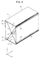
- the device 15 shown in Figure 3 is likely to absorb higher energy shocks than the device described above.
- the basic structure is same as that of FIG. 1 where the same elements bear the same references.
- the angles between triangles 2 and 3 are here closed by thin plates 16 and 17 welded by weld beads 18, 19 and 20, 21 respectively on the rest of the element.
- a damping device can combine several elements such as elements 1 and 15, in parallel with so as to absorb a shock occurring on a surface relatively large. You can use such a device on rail vehicles to absorb severe shocks occurring in the event of an accident. It is then particularly advantageous to integrate this device into a chassis railway vehicle to constitute a "fuse" zone in shock.
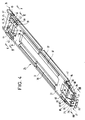
- FIG. 4 represents a chassis 25 of a vehicle rail with two damping devices shock 26 and 27 according to the invention.
- the chassis includes two stretchers 31 and 32 between which are arranged two pivot sleepers intended to rest on bogies: the front pivot cross member 33 and rear pivot cross member 34.
- a the rear, the stretchers 31 and 32 are joined by a rear cross member 35.
- the stretchers 31 and 32 and the front pivot cross member 33 is extended by a front part including the damping device 27.
- the shock absorbing device 26 is inserted in the frame 25 between the rear crossmember 35 and the ends of the stretchers 31, 32 and the pivot crosspiece 34.
- the device 26 has several elements.
- the external elements 42 and 43 are inserted in the stretchers 31 and 32.
- the interior elements 44 and 45 extend the elements 38 and 39 to the rear crossmember 35.
- Elements 44 and 45 are made integral by welding of the rear crossmember 35 via reinforced parts 46 and 47 widening towards the crosspiece rear 35. These parts 46 and 47 serve as bases for elements 44 and 45.
- Element 44 is made integral by welding of element 38 with interposition of a plate metal serving as a base for element 44. So does even for the connection between element 45 and element 39.
- a intermediate crosspiece 48 is welded between the elements 38 and 39 near elements 44 and 45.
- Elements 42 and 43 are inserted by welding with stretchers 31 and 32 with interposition of metal plates serving as bases for these elements.
- the stretchers are reinforced at their junction with elements 42 and 43 by reinforcement pieces 49. These reinforcement pieces as well as the proximity of pivot cross member 34 and rear cross member 35, stiffening the stretchers, make these parts of stretchers can be considered non-deformable by compared to the damping device.
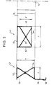
- Figure 5 shows only the left side of the V-V section shown in Figure 4, the right side being symmetrically identical.
- Axis 51 represents the axis central and vertical of the vehicle.
- Elements 42 and 44 y are seen in section.
- the element 42 is of the type shown in the figure 1. It is formed from several thin plates 52, 53 and 54 folded if necessary and welded together. For the purposes of hanging the sheets from the side faces, it is necessary and not disturbing for the system there add an appendix 56 located at the bottom and welded to an extension 55 of the plate 52.
- the element 44 is of the type represented in FIG. 3. It is formed from several thin plates 61, 62, 63, 64 and 65 folded if necessary and welded together. The element 44 thus has the same external shape as the chassis beams.
- the plates 52, 53, 61, 62 and 65 can be of grade steel E24, the steel plates 63 and 64 of grade E36 and the plates 55 and 56 in grade E490D steel.
- the thickness of the plates can be 4 mm for a height h of 195 mm and a width 1 of 110 mm for element 42, and for a height h 'of 130 mm and a width 1 'of 220 mm for element 44.
- Figure 6 shows only the left side of the section VI-VI shown in Figure 4, the right side being symmetrically identical.
- the axis 71 represents the axis central and vertical of the vehicle.
- the stretcher 31 and the element 38 are seen in section.
- the stretcher 31 is formed of a plate 71 folded.
- the element 38 is formed by welding the plates 69, 70, 72, 73 and 74.
- the device shock absorbing 27 comprises a central element 75 placed along the longitudinal center line of the vehicle and two side elements 76 and 77 arranged in V pointing towards the front.
- This device is located between a plate front end 78 intended to receive a possible shock and a cross member 79 connected to the rest of the chassis by a structure rigid mechanics ensuring transmission of forces between the cross member 79 and the front pivot cross member 33.
- This rigid structure includes sills 40 and 41, cross members 80, 81 and 82 and beams 83, 84, 85, 86, 87 and 88.
- Figure 7 shows the elements 75, 76 and 77 in section.
- the element 75 is of the type shown in FIG. 3. It is formed from several thin plates 89, 90, 91, 92, 93, 67 and 68 welded together.
- Elements 76 and 77 do not have this structure in X characteristic of the invention.
- Element 76 is formed from several thin plates 94, 95 and 96 folded on if applicable and welded together. Plate 94 forms a diagonal for the rectangle formed by the section of item 76. This diagonal goes from the left side up towards the right side down.
- Element 77 is formed from several plates thin 97, 98 and 99 folded if necessary and welded between they.
- Plate 97 forms a diagonal for the rectangle formed by the section of the element 77. This diagonal goes from right side up towards the left side down.
- Figure 8 shows a front frame of a box railway vehicle comprising first 97, second 98, third 103 and fourth 104 shock absorption devices obtained according to the modes described below.
- the front frame of the rail vehicle body includes a frame 25 consisting of two stretchers 31 and 32 between which a front pivot cross member 33 is arranged resting on a front bogie.
- a first 89 and a second 90 rigid ring constitute a security cell 91.
- Longrines 92 and 93 and armatures 94 and 95 are integral with the rings rigid so as to stiffen the safety cell.
- a first deformable zone 96 making up the part before the frame, consists of the first 97 and second 98 shock absorbers as well as a drawbar 122.
- the first shock absorption devices 97 are arranged, respectively, on both sides of the axis central of the chassis 25. These first devices shock absorption have a general trapezoid shape and each consist of a longitudinal element 1 conforming to the invention whose upper and lower faces are integral with trapezoidal plates 99 and 100.
- the second shock absorption devices 98 are made up of an element of the known honeycomb type state of the art. These second devices shock absorbers are, for example, arranged on the first shock absorption devices 97, the whole bearing against a retaining plate 101.
- the drawbar 122 known from the state of the technique is arranged longitudinally, preferably between the first absorber elements 97 in the first zone deformable 96.
- a second deformable zone 102 is disposed between the first deformable zone 96 and the security cell 91.
- the second deformable zone 102 consists of third 103 and fourth 104 devices shock absorption, respectively in the lower part and in the upper part of this second deformable zone.
- the third shock absorption devices 103 each consist of first 105 and second 106 absorbers according to the invention. These first 105 and second 106 absorbers are arranged in the form of V and their upper and lower faces are integral of plates 107 and 108.
- the plates 107 and 108 are preferably trapezoidal so as to dampen the initial effort of a frontal impact applied to third devices shock absorption 103.
- the third shock absorption devices are arranged in the plane of the chassis 25 and are supported against a cross member 109.
- the cross member 109 is integral with its ends of the base of the first rigid ring 89.
- the fourth shock absorption devices 104 each consist of first 110 and second 111 absorbers. These first 110 and second 111 absorbers are arranged in a V shape and their upper and lower faces are integral with plates 112 and 113.
- the plates 112 and 113 are preferably trapezoidal so as to dampen the initial effort of a frontal impact applied to the fourth devices shock absorption 104.
- the fourth shock absorption devices are arranged in the extension of the upper part the first rigid ring 89 and the second elements absorbers 98.
- the plates triangular 112 and 113 can be a single plane ( Figures 13 a and b) or two planes as shown in Figure 8.
- the other ends of the damping devices shock 104 are supported on the retaining plate 101 by through a support framework 118.
- a guide means 119 integral with the chassis 25 is arranged longitudinally parallel to the longitudinal axis of the chassis 25.
- Figure 9 is a partial view of the framework of rail vehicle body of figure 8 according to section IX-IX.
- Elements 105 and 106 and trapezoidal plates 107 and 108 are seen in section. Elements 105 and 106 are of the type shown in Figures 1 to 3 and as described previously.
- the trapezoidal plates 107, 108 have the effect essential to keep the elements under tension longitudinal absorbers 105, 106.
- third shock absorber 103 is a accordion plastic deformation so that the template of the shock absorption device is kept.
- Figure 10 is a partial view of the framework of rail vehicle body of figure 8 according to section X-X.
- Elements 110 and 111 and trapezoidal plates 112 and 113 are seen there in section.
- the first 110 and second 111 absorbers each consist of a single longitudinal element absorber different from those shown in Figures 1 to 3.
- the section of the longitudinal element has the shape general of a rectangle including two of the opposite faces 114 and 115 are parallel and of which the two other opposite faces 116 and 117 form with one of the parallel faces a longitudinal absorber element of cross section of general triangular shape.
- fourth shock absorber 104 is a accordion plastic deformation so that the template of the shock absorption device is kept.
- a primary consequence of deformations in vertical planes of third 103 and fourth 104 shock absorbing devices is that part of support 118 and the first rigid ring 89 both remain parallel to each other during a shock frontal.
- Figure 11 is a sectional view of the framework of the rail vehicle body of Figure 8.
- the chassis 25 made up of the two stretchers 31 and 32 between which the front pivot cross member 33 resting on the front bogie.
- the first 89 and the second 90 rigid ring constitute the security cell 91.
- the sills 92 and 93 are integral with the rigid rings.
- the first deformable zone 96 making up the part before the frame, consists of the first 97 and second (not shown) absorbers as well as a drawbar 122.
- the first shock absorption devices 97 are arranged, respectively, on both sides of the axis central of the chassis 25. These first devices shock absorption have a general trapezoid shape and each consist of a longitudinal element 1 conforming to the invention.
- the first shock absorption devices 97 bear against the retaining plate 101, which is attached to the support frame 118.
- the second deformable zone 102 is disposed between the first deformable zone 96 and the security cell 91.
- the second deformable zone 102 consists of third 103 and fourth (not shown) shock absorbing devices.
- the third shock absorption devices 103 each consist of a first 105 and a second 106 absorber element according to the invention, the faces of which upper and lower are secured to plates trapezoidal 107 and 108.
- the third shock absorption devices 103 are arranged in the plane of the chassis 25 and take support against a cross member 109.
- the cross member 109 is integral at its ends of the base of the first rigid ring 89.
- the guide means 119 integral with the chassis 25 is longitudinally arranged parallel to the longitudinal axis of the chassis 25.
- This guide means 119 is composed, in accordance in the preferred embodiment, of the longitudinal drawer 120 capable of sliding in the longitudinal guide 121.
- the longitudinal guide 121 is fixed, integral with the chassis 25 and is delimited by the length of the security cell 91.
- the longitudinal drawer 120 is fixed to one of its ends, for example at the support frame 118, so as to slide in the longitudinal guide 121 by the other of its ends.
- the drawbar 122 is arranged longitudinally, preferably between the first absorber elements 97 in the first deformable zone 96.
- This drawbar 122 bears against a first support sole 123 in such a way that this support sole 123 and the end of the drawbar 122 are likely to slide in the guide longitudinal 121.
- First 124, second 126 and third 128 longitudinal absorbers, all three conforming to the invention, are arranged free to slide in the drawer longitudinal 120.
- These longitudinal absorber elements conform to the invention then constitute, respectively, fifth, sixth and seventh devices shock absorption.
- the first 124 and second 126 elements longitudinal support against a second base support 125 in such a way that this second sole 125 is likely to slide in the guide longitudinal 121.
- the second 126 and third 128 elements longitudinal support against the third base support 127 in such a way that this third sole 127 are likely to slide in the drawer longitudinal 120, see in longitudinal guide 121.
- the third 128 longitudinal elements take support against a fourth support base 129, which is integral with the pivot cross member 33.
- Table 1 brings together the main technical data of each of the shock absorption devices used in the front frame of a rail vehicle body according to the preferred embodiment of the invention.
- SHOCK ABSORBER DEVICE LONGITUDINAL ABSORBER ELEMENT MATERIAL (STEEL) WIDTH mm HEIGHT mm EFFORT RECEIVED kN 97 (first) 1 Z8 CN 12 250 150 1000 98 (second) known from the state of the art 103 (third) 105 Z8 CN 12 100 150 400 106 104 (fourth) 110 Z8 CN 12 200 150 900 111 124 (fifth) 124 Z8 CN 12 250 170 1100 126 (sixth) 126 Z8 CN 12 250 170 1400 128 (seventh) 128 Z8 CN 12 250 250 1700-2500
- shock absorbing devices undergo a crush.
- the crushing of the damping devices of shock results in an accordion deformation of longitudinal absorbers. This deformation takes place in a vertical plane moving in the direction of the shock.
- the deformation in accordion of the elements is achieved by keeping approximately the gauge of the elements.
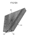
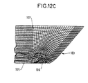
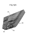
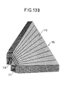
- Figures 12 a to d and 13 a and b show different stages of evolution, respectively third 103 and fourth 104 devices shock absorption, when crushed.
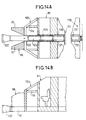
- Figures 14a, b to 17a, b show the four successive phases of deformation of the body of the body of a railway vehicle incorporating the devices shock absorption according to the invention.
- the connecting bar 130 comprises, for example, a longitudinal absorber element 131 and as shown in Figures 1 to 3, the end of which external is likely to slide in a guide longitudinal 132 secured to the frame 25 of the frame.
- the link bar 130 therefore constitutes an eighth shock absorption device.
- Table 2 gives the technical data relating to this eighth shock absorption device used in the rear frame of the body of the rail vehicle.
- the first phase is suitable for vehicle speeds between 0 and 3 m / s.
- the shock is absorbed by the elastic deformation of the drawbar 122.
- Drawbar 122 undergoes elastic displacement longitudinal so as to be inserted in the drawer longitudinal 120 without deformation of the framework, in especially shock absorbing devices.
- the longitudinal displacement of the drawbar 122 is about 190 mm from its initial position.
- the initial position (before the shock) and the final position (at the end of phase I) of the bar coupling 122 are shown in Figures 14 a and b.
- the second phase represented in FIGS. 15 a and b, is suitable for vehicle speeds between 3 and 5 m / s.
- Drawbar 122 undergoes displacement longitudinal and continuous to enter the drawer longitudinal 120.
- the longitudinal displacement of the drawbar 122 is of the order of 550 mm relative to its position at the end of phase I, i.e. a displacement of 740 mm from its original position.
- the initial position and the final position (at the end of phase II) of the bar coupling 122 are shown in Figures 15 a and b.
- the third phase shown in Figures 16 a and b, is suitable for vehicle speeds between 5 and 10 m / s.
- the longitudinal displacement of the drawbar 122 is about 576 mm from its position at the end of phase II, i.e. a displacement of about 1286 mm from its initial position.
- the initial position and final position (at the end of the phase III) of the drawbar 122 are shown in Figures 16 a and b.
- the fourth phase is suitable for vehicle speeds above 10 m / s.
- the longitudinal displacement of the drawbar 122 is around 480 mm from its position at the end of phase III, i.e. a displacement of around 1766 mm from its initial position.
- the initial position and final position (at the end of phase IV) of the drawbar 122 are shown in Figures 17 a and b.
Landscapes
- Engineering & Computer Science (AREA)
- Mechanical Engineering (AREA)
- General Engineering & Computer Science (AREA)
- Transportation (AREA)
- Chemical & Material Sciences (AREA)
- Combustion & Propulsion (AREA)
- Vibration Dampers (AREA)
- Body Structure For Vehicles (AREA)
Description
- la figure 1 représente un dispositif d'amortissement de choc, ce dispositif étant constitué alun seul élément longitudinal,
- la figure 2 représente une variante de réalisation d'un dispositif d'amortissement de choc,
- la figure 3 représente un dispositif d'amortissement de choc selon l'invention,
- la figure 4 représente un châssis de véhicule ferroviaire incorporant des dispositifs d'amortissement de choc selon l'invention,
- la figure 5 est une vue partielle du châssis du véhicule ferroviaire de la figure 4 selon la coupe V-V,
- la figure 6 est une vue partielle du châssis du véhicule ferroviaire de la figure 4 selon la coupe VI-VI,
- la figure 7 est une vue du châssis du véhicule ferroviaire de la figure 4 selon la coupe VII-VII,
- la figure 8 représente une ossature d'une caisse de véhicule ferroviaire incorporant des dispositifs d'amortissement de choc selon l'invention,
- la figure 9 est une vue partielle de l'ossature d'une caisse de véhicule ferroviaire de la figure 8 selon la coupe IX-IX,
- la figure 10 est une vue partielle de l'ossature d'une caisse de véhicule ferroviaire de la figure 8 selon la coupe X-X,
- la figure 11 est une vue en coupe de l'ossature de la caisse de véhicule ferroviaire de la figure 8,
- les figures 12 a à d et 13 a et b représentent différents stades de l'évolution, respectivement des troisièmes et des quatrièmes dispositifs d'amortissement de choc, lors de leur écrasement,
- les figures 14a,b à 17a,b représentent les quatre phases successives de déformation de l'ossature de la caisse de véhicule ferroviaire incorporant les dispositifs d'amortissement de choc selon l'invention.
| DISPOSITIF D'AMORTISSEMENT DE CHOC | ELEMENT LONGITUDINAL ABSORBEUR | MATERIAU (ACIER) | LARGEUR mm | HAUTEUR mm | EFFORT RECU kN |
| 97 (premier) | 1 | Z8 CN 12 | 250 | 150 | 1000 |
| 98 (deuxième) | connu de l'état de la technique | ||||
| 103 (troisième) | 105 | Z8 CN 12 | 100 | 150 | 400 |
| 106 | |||||
| 104 (quatrième) | 110 | Z8 CN 12 | 200 | 150 | 900 |
| 111 | |||||
| 124 (cinquième) | 124 | Z8 CN 12 | 250 | 170 | 1100 |
| 126 (sixième) | 126 | Z8 CN 12 | 250 | 170 | 1400 |
| 128 (septième) | 128 | Z8 CN 12 | 250 | 250 | 1700-2500 |
| DISPOSITIF D'AMORTISSEMENT DE CHOC | ELEMENT LONGITUDINAL ABSORBEUR | MATERIAU (ACIER) | LARGEUR mm | HAUTEUR mm | EFFORT RECU kN |
| 130 (huitième) | 131 | Z8 CN 12 | 1100 |
Claims (10)
- Un dispositif d'amortissement de choc comprenant un élément (105,106) qui s'étend suivant une direction longitudinale et qui est apte à absorbe l'énergie engendrée par un choc se produisant suivant ladite direction en se déformant suivant cette direction, l'élément étant constitué en plaque mince, caractérisé en ce qu'il comprend une première plaque mince (16) parallèle à une seconde plaque mince (17) s'étendant suivant ladite direction longitudinale et en ce qu'il présente une section, dans un plar perpendiculaire à ladite direction longitudinale, ayant la forme de deux triangles ayant des bases parallèles et un sommet commun, les bases des deux triangles étant reliées entre elles par la première et par la seconde plaque mince.
- Le dispositif selon la revendication 1, dans lequel ledit élément comporte des renforts (11) disposés dans des plans perpendiculaires à ladite direction.
- Le dispositif selon la revendication 1, dans lequel ledit élément comporte des zones embouties (14).
- Le dispositif selon l'une des revendications 1 à 3, dans lequel ledit élément est en acier.
- Le dispositif selon l'une des revendications 1 à 4, dans lequel ladite section présente des parties ayant des coefficients de limite élastique différents.
- Le dispositif selon l'une des revendications 1 à 5, dans lequel ledit élément est constitué de plaques minces (5) pliées et soudées entre elles pour former ladite section.
- Un véhicule comprenant un châssis (25) et une cellule de sécurité (91) disposée à l'avant du châssis, la cellule de sécurité ayant une ossature dont la partie frontale comporte une première zone déformable (96) en cas de choc frontal, cette première zone déformable comprenant un premier dispositif d'amortissement de choc (97) selon l'une des revendications 1 à 6 de part et d'autre de l'axe central du châssis, ce premier dispositif d'amortissement de choc s'étendant longitudinalement parallèlement à cet axe central.
- Le véhicule selon la revendication 7, dans lequel l'ossature de la cellule de sécurité (91) comprend un anneau rigide (89) solidaire du châssis et séparé de la première zone déformable par une seconde zone déformable (102) en cas de choc frontal, cette seconde zone déformable (102) comprenant un second (106) et un troisième (105) dispositif d'amortissement de choc selon l'une des revendications 1 à 6 de part et d'autre de l'axe central du châssis, le second et le troisième dispositif d'amortissement de choc étant disposés en V et étant solidaires l'un de l'autre par des plaques trapézoïdales (107,108), le second dispositif d'amortissement de choc s'étendant longitudinalement parallèlement à l'axe central du châssis.
- Le véhicule selon la revendication 8, dans lequel le châssis (25) comprend deux brancards (31,32) parallèles à l'axe central du châssis et séparés l'un de l'autre par une traverse (33) disposée en arrière de la cellule de sécurité (91), une barre d'attelage (122) qui traverse la première zone déformable (96) parallèlement à l'axe central du châssis, un guide longitudinal (121) qui est solidaire du châssis et de la cellule de sécurité et qui s'étend parallèlement à l'axe central du châssis, un tiroir longitudinal (120) ayant une extrémité solidaire de la seconde zone déformable (102) et une autre extrémité apte à coulisser sans déformation à l'intérieur du guide longitudinal, la barre d'attelage ayant une extrémité engagée à l'intérieur du tiroir longitudinal et prenant appui contre la traverse par l'intermédiaire d'au moins un dispositif amortisseur de choc (124) selon l'une des revendications 1 à 6 qui s'étend longitudinalement parallèlement à l'axe central du châssis à l'intérieur du guide ou du tiroir entre ladite extrémité de la barre d'attelage et la traverse.
- Le véhicule selon la revendication 9, dans lequel il est prévu plusieurs dispositifs d'amortissement de choc (124,126,128) selon l'une des revendications 1 à 6 disposés en série entre ladite extrémité de la barre d'attelage et la traverse.
Applications Claiming Priority (2)
| Application Number | Priority Date | Filing Date | Title |
|---|---|---|---|
| FR9314096A FR2712950B1 (fr) | 1993-11-25 | 1993-11-25 | Dispositifs et procédé d'amortissement de choc, ossature et véhicule comportant de tels dispositifs d'amortissement de choc. |
| FR9314096 | 1993-11-25 |
Publications (2)
| Publication Number | Publication Date |
|---|---|
| EP0655565A1 EP0655565A1 (fr) | 1995-05-31 |
| EP0655565B1 true EP0655565B1 (fr) | 1999-10-06 |
Family
ID=9453217
Family Applications (1)
| Application Number | Title | Priority Date | Filing Date |
|---|---|---|---|
| EP94400877A Expired - Lifetime EP0655565B1 (fr) | 1993-11-25 | 1994-04-22 | Dispositifs et procédé d'amortissement de choc, ossature et véhicule comportant de tels dispositifs d'amortissement de choc |
Country Status (6)
| Country | Link |
|---|---|
| US (3) | US5579699A (fr) |
| EP (1) | EP0655565B1 (fr) |
| JP (1) | JP3734282B2 (fr) |
| CA (1) | CA2120869C (fr) |
| DE (1) | DE69421043T2 (fr) |
| FR (1) | FR2712950B1 (fr) |
Families Citing this family (132)
| Publication number | Priority date | Publication date | Assignee | Title |
|---|---|---|---|---|
| FR2712950B1 (fr) * | 1993-11-25 | 1995-12-29 | Gec Alsthom Transport Sa | Dispositifs et procédé d'amortissement de choc, ossature et véhicule comportant de tels dispositifs d'amortissement de choc. |
| GB2305487A (en) * | 1995-09-15 | 1997-04-09 | Darchem Eng Ltd | An impact energy absorber having a low initiation load |
| JP3539049B2 (ja) * | 1996-03-15 | 2004-06-14 | 日産自動車株式会社 | 部材の結合構造 |
| FR2747633B1 (fr) * | 1996-04-19 | 2003-01-31 | Alstom Ddf | Vehicule ferroviaire a cabine de conduite comportant une structure absorbeuse d'energie a deformation progressive |
| US5853195A (en) * | 1997-01-16 | 1998-12-29 | Ford Global Technologies, Inc. | Front rail assembly for a vehicle |
| BE1010869A3 (fr) * | 1997-01-20 | 1999-02-02 | Cockerill Rech & Dev | Dispositif d'absorption d'energie. |
| CH691731A5 (de) * | 1997-03-11 | 2001-09-28 | Alusuisse Tech & Man Ag | Fahrzeug mit Stossstange und Deformationselement. |
| DE19720329C1 (de) | 1997-05-15 | 1998-11-05 | Abb Daimler Benz Transp | Schienenfahrzeug mit Stoßverzehrelementeinrichtung |
| FR2765543B1 (fr) * | 1997-07-02 | 2005-01-07 | Alstom Ddf | Vehicule ferroviaire comportant au moins un module d'extremite interchangeable |
| EP0903274A1 (fr) * | 1997-09-18 | 1999-03-24 | Alusuisse Technology & Management AG | Dispositif de montage d'un attelage de véhicule |
| CZ284735B6 (cs) * | 1997-09-30 | 1999-02-17 | VÚKV a.s. | Představek železničního vozu |
| US6062634A (en) * | 1997-11-17 | 2000-05-16 | Daimlerchrysler Corporation | Automotive energy absorbing structure |
| US6068330A (en) * | 1998-01-22 | 2000-05-30 | Honda Giken Kogyo Kabushiki Kaisha | Framework of an automobile body |
| US6196135B1 (en) * | 1998-04-17 | 2001-03-06 | Kinki Sharyo Co., Ltd. | Shock absorbing underframe structure for railroad car |
| FR2783887B1 (fr) * | 1998-09-28 | 2000-11-10 | Alstom Technology | Structure d'amortissement de choc |
| US6158771A (en) | 1998-10-23 | 2000-12-12 | Hexcel Corporation | Honeycomb crash pad |
| FR2785028B1 (fr) | 1998-10-23 | 2000-12-15 | Dytesys | Dispositif amortisseur de chocs |
| US6245408B1 (en) | 1999-05-19 | 2001-06-12 | Hexcel Corporation | Honeycomb core with controlled crush properties |
| US6668457B1 (en) | 1999-12-10 | 2003-12-30 | L&L Products, Inc. | Heat-activated structural foam reinforced hydroform |
| FR2803899B1 (fr) * | 2000-01-17 | 2002-04-05 | Ecia Equip Composants Ind Auto | Element structurel comprenant un corps et des nervures de renfort et vehicule automobile correspondant |
| US6467834B1 (en) | 2000-02-11 | 2002-10-22 | L&L Products | Structural reinforcement system for automotive vehicles |
| WO2001058741A1 (fr) * | 2000-02-11 | 2001-08-16 | L & L Products, Inc. | Systeme de renfort structurel pour vehicules automobiles |
| AT408874B (de) * | 2000-02-18 | 2002-03-25 | Siemens Sgp Verkehrstech Gmbh | Deformationselement für ein schienenfahrzeug |
| AT408875B (de) * | 2000-02-18 | 2002-03-25 | Siemens Sgp Verkehrstech Gmbh | Deformationselement eines schienenfahrzeuges |
| US6482486B1 (en) | 2000-03-14 | 2002-11-19 | L&L Products | Heat activated reinforcing sleeve |
| JP3848821B2 (ja) * | 2000-08-28 | 2006-11-22 | 三菱重工業株式会社 | 車体構造 |
| WO2002018189A1 (fr) * | 2000-08-28 | 2002-03-07 | Mitsubishi Heavy Industries, Ltd. | Structure de corps |
| US6471285B1 (en) | 2000-09-29 | 2002-10-29 | L&L Products, Inc. | Hydroform structural reinforcement system |
| US6561571B1 (en) | 2000-09-29 | 2003-05-13 | L&L Products, Inc. | Structurally enhanced attachment of a reinforcing member |
| DE10062802B4 (de) * | 2000-12-15 | 2006-11-09 | Audi Ag | Deformationselement für ein Kraftfahrzeug |
| GB0106911D0 (en) * | 2001-03-20 | 2001-05-09 | L & L Products | Structural foam |
| JP3512753B2 (ja) | 2001-04-20 | 2004-03-31 | 川崎重工業株式会社 | 鉄道車両の衝突エネルギ吸収構造 |
| GB2375328A (en) | 2001-05-08 | 2002-11-13 | L & L Products | Reinforcing element for hollow structural member |
| US6502821B2 (en) * | 2001-05-16 | 2003-01-07 | L&L Products, Inc. | Automotive body panel damping system |
| JP4576780B2 (ja) * | 2001-09-21 | 2010-11-10 | マツダ株式会社 | 車体のフレーム構造及び車体フレームの製造方法 |
| US6786533B2 (en) * | 2001-09-24 | 2004-09-07 | L&L Products, Inc. | Structural reinforcement system having modular segmented characteristics |
| JP3725057B2 (ja) * | 2001-09-25 | 2005-12-07 | 株式会社日立製作所 | 軌条車両 |
| JP2003095097A (ja) | 2001-09-25 | 2003-04-03 | Hitachi Ltd | 軌条車両 |
| US6793274B2 (en) * | 2001-11-14 | 2004-09-21 | L&L Products, Inc. | Automotive rail/frame energy management system |
| US6971471B2 (en) * | 2001-12-07 | 2005-12-06 | General Motors Corporation | Multi-directional drive |
| JP3941563B2 (ja) * | 2002-04-02 | 2007-07-04 | 日産自動車株式会社 | 車両前部構造 |
| US7077460B2 (en) | 2002-04-30 | 2006-07-18 | L&L Products, Inc. | Reinforcement system utilizing a hollow carrier |
| US7004502B2 (en) * | 2002-07-25 | 2006-02-28 | General Motors Corporation | Frontal impact energy dissipation zone |
| US6755453B2 (en) * | 2002-08-29 | 2004-06-29 | Veridian Systems Division, Inc. | Deployable rigid system for crash energy management |
| JP3848227B2 (ja) * | 2002-09-02 | 2006-11-22 | 株式会社日立製作所 | 軌条車両 |
| US6883858B2 (en) * | 2002-09-10 | 2005-04-26 | L & L Products, Inc. | Structural reinforcement member and method of use therefor |
| JP4912559B2 (ja) * | 2002-09-11 | 2012-04-11 | 株式会社日立製作所 | 軌条車両 |
| KR100498261B1 (ko) * | 2002-10-28 | 2005-06-29 | 한국생산기술연구원 | 열차의 전두부 구조 |
| US7105112B2 (en) | 2002-11-05 | 2006-09-12 | L&L Products, Inc. | Lightweight member for reinforcing, sealing or baffling |
| US6698819B1 (en) * | 2002-12-10 | 2004-03-02 | Lear Corporation | Pneumatic pressure molded impact countermeasure |
| EP1468889B1 (fr) * | 2003-04-14 | 2009-06-17 | Kawasaki Jukogyo Kabushiki Kaisha | Attelage central pour un véhicule ferroviaire, avec un amortisseur caoutchouc et un élément d' absorption d' énergie |
| CN1323004C (zh) * | 2003-04-16 | 2007-06-27 | 川崎重工业株式会社 | 铁路车辆的排障板支承结构 |
| DE60327991D1 (de) * | 2003-04-19 | 2009-07-30 | Kawasaki Heavy Ind Ltd | Tragstruktur des Bahnräumers von einem Schienenfahrzeug |
| GB2401349A (en) | 2003-05-08 | 2004-11-10 | L & L Products | Reinforcement for a vehicle panel |
| GB2404635B (en) * | 2003-08-08 | 2007-03-07 | Bombardier Transp | Energy absorpotion device for absorbing impact energy of a vehicle |
| WO2005028275A1 (fr) * | 2003-09-19 | 2005-03-31 | Siemens Transportation Systems, Inc. | Systeme de protection d'impact integre |
| GB2411633A (en) * | 2004-03-01 | 2005-09-07 | Bombardier Transp Gmbh | Railway vehicle with cabin having a collapsible front section |
| GB2411630A (en) * | 2004-03-01 | 2005-09-07 | Bombardier Transp Gmbh | Vehicle cabin frame with yieldable regions |
| GB2411632A (en) * | 2004-03-01 | 2005-09-07 | Bombardier Transp Gmbh | Rail vehicle cabin with yieldable parts |
| DE102004016216A1 (de) * | 2004-04-01 | 2005-10-20 | Siemens Ag | Wagenkasten eines Schienenfahrzeuges mit einer Vorrichtung zur gezielten Absorption von Kollisionsenergie |
| US7637559B2 (en) | 2004-04-02 | 2009-12-29 | Gm Global Technology Operations, Inc. | Volume-filling mechanical assemblies and methods of operating the same |
| US7374231B2 (en) * | 2004-04-02 | 2008-05-20 | Gm Global Technology Operations, Inc. | Force and deceleration delimiting devices and methods for operating the same |
| US7401846B2 (en) * | 2004-04-02 | 2008-07-22 | Gm Global Technology Operations, Inc. | Volume-filling mechanical assemblies and methods of operating the same |
| US20050218696A1 (en) * | 2004-04-02 | 2005-10-06 | Aase Jan H | Methods for modifying a crash deceleration pulse |
| DE102004028964A1 (de) * | 2004-05-07 | 2005-12-01 | Siemens Ag | Fahrzeug mit Deformationszone |
| GB2415658A (en) | 2004-06-21 | 2006-01-04 | L & L Products Inc | An overmoulding process |
| AT504300B1 (de) * | 2004-07-28 | 2009-12-15 | Siemens Transportation Systems | Aufkletterschutz bei eisenbahnfahrzeugen |
| US7168880B2 (en) | 2004-11-17 | 2007-01-30 | Battelle Memorial Institute | Impact attenuator system |
| FR2879549B1 (fr) * | 2004-12-22 | 2007-02-09 | Alstom Transport Sa | Dispositif absorbeur de chocs pour vehicule ferroviaire |
| AT501689A1 (de) * | 2005-04-04 | 2006-10-15 | Siemens Transportation Systems | Schienenfahrzeug mit kollisionstauglicher kupplungsanbindung |
| US7503620B2 (en) | 2005-05-12 | 2009-03-17 | Zephyros, Inc. | Structural reinforcement member and method of use therefor |
| JP2006341714A (ja) * | 2005-06-08 | 2006-12-21 | Yoshinori Tsukiyama | 衝撃緩衝車両 |
| DE102005029738B4 (de) * | 2005-06-24 | 2018-10-04 | GM Global Technology Operations LLC (n. d. Ges. d. Staates Delaware) | Energieabsorberelement und dieses verwendende Kraftfahrzeugkarosserie |
| DE102005041894B4 (de) * | 2005-09-03 | 2007-12-13 | Audi Ag | Trägerelement, insbesondere in einem Kraftfahrzeug |
| JP2007161128A (ja) * | 2005-12-15 | 2007-06-28 | Nippon Sharyo Seizo Kaisha Ltd | 鉄道車両用衝撃吸収構造 |
| GB0600901D0 (en) | 2006-01-17 | 2006-02-22 | L & L Products Inc | Improvements in or relating to reinforcement of hollow profiles |
| DE102006019654A1 (de) * | 2006-04-25 | 2007-11-08 | Alcan Technology & Management Ag | Profilelement zum Befestigen einer Stoßstange an Längsträgern eines Fahrzeuges sowie Verfahren dazu |
| US8454064B2 (en) * | 2006-04-25 | 2013-06-04 | GM Global Technology Operations LLC | Arrangement and method for attaching a bumper to side members of a vehicle |
| JP4261589B2 (ja) * | 2006-05-10 | 2009-04-30 | 株式会社日立製作所 | 衝突エネルギー吸収装置及びそれを備えた軌条車両 |
| JP4943905B2 (ja) | 2006-05-10 | 2012-05-30 | 株式会社日立製作所 | 衝突エネルギー吸収装置及びそれを備えた軌条車両 |
| JP4712604B2 (ja) * | 2006-05-10 | 2011-06-29 | 株式会社日立製作所 | 輸送機器 |
| JP5179053B2 (ja) * | 2006-05-10 | 2013-04-10 | 株式会社日立製作所 | 衝突エネルギー吸収装置及びそれを備えた軌条車両 |
| EP1854690B1 (fr) * | 2006-05-10 | 2011-08-10 | Hitachi, Ltd. | Dispositif d'absorption d'énergie en cas de collision et véhicule ferroviaire équipé d'un tel dispositif |
| KR100797046B1 (ko) | 2006-09-05 | 2008-01-22 | 한국철도기술연구원 | 슬라이딩 방식 전두부 충격에너지 흡수장치 |
| JP5092323B2 (ja) * | 2006-09-08 | 2012-12-05 | 株式会社日立製作所 | 軌条車両 |
| DE102006043923B4 (de) * | 2006-09-14 | 2009-12-03 | Voith Turbo Lokomotivtechnik Gmbh & Co. Kg | Lokomotivkasten |
| DE102006043924B4 (de) * | 2006-09-14 | 2009-01-02 | Voith Turbo Lokomotivtechnik Gmbh & Co. Kg | Lokomotive |
| DE102006043925B4 (de) * | 2006-09-14 | 2014-07-17 | Voith Turbo Lokomotivtechnik Gmbh & Co. Kg | Lokomotive |
| JP4845688B2 (ja) * | 2006-11-21 | 2011-12-28 | 株式会社日立製作所 | 車両 |
| CZ2006736A3 (cs) * | 2006-11-24 | 2008-01-16 | Ĺ KODA TRANSPORTATION s. r. o. | Kabina železničního vozidla s definovanou deformací |
| ITTO20060863A1 (it) * | 2006-12-04 | 2008-06-05 | Ansaldobreda Spa | Carrozza di testa di un treno provvista di una struttura frontale che assorbe energia in caso di collisione |
| JP4909092B2 (ja) * | 2007-01-10 | 2012-04-04 | 本田技研工業株式会社 | 軽合金製の押出フレーム |
| JP4919409B2 (ja) * | 2007-01-24 | 2012-04-18 | ルネサスエレクトロニクス株式会社 | 半導体装置製造方法 |
| US7690314B2 (en) * | 2007-04-12 | 2010-04-06 | Siemens Industry, Inc. | Rail car collision system |
| JP4809298B2 (ja) * | 2007-06-22 | 2011-11-09 | 日本車輌製造株式会社 | 鉄道車両 |
| KR100916596B1 (ko) * | 2007-12-06 | 2009-09-11 | 한국철도기술연구원 | 철도차량 전두부의 충격흡수 구조 |
| CN102015813B (zh) * | 2008-03-17 | 2013-05-22 | 巴特勒纪念研究院 | 回弹控制材料 |
| JP2009241772A (ja) * | 2008-03-31 | 2009-10-22 | Hitachi Ltd | 軌条車両 |
| EP2301809B1 (fr) * | 2008-07-23 | 2013-06-12 | Toyotomi Kiko Co., Ltd. | Elément d absorption de chocs |
| BRPI0917647A2 (pt) * | 2008-09-15 | 2015-11-17 | Voith Patent Gmbh | módulo para ser instalado na extremidade dianteira de um veículo de trilhos, em especial um veículo ferroviário. |
| US8701566B2 (en) | 2009-03-25 | 2014-04-22 | West Japan Railway Company | Railcar |
| AT509376B1 (de) * | 2010-02-11 | 2011-11-15 | Siemens Ag Oesterreich | Crashmodul für ein schienenfahrzeug |
| US8469626B2 (en) | 2010-04-15 | 2013-06-25 | Energy Absorption Systems, Inc. | Energy absorbing vehicle barrier |
| AT509833B1 (de) * | 2010-04-26 | 2012-03-15 | Siemens Ag Oesterreich | Verstärkter langträger für ein schienenfahrzeug |
| AT511291A1 (de) * | 2011-04-04 | 2012-10-15 | Siemens Ag Oesterreich | Schienenfahrzeug mit angesetzter verformungszone |
| AT511290A1 (de) * | 2011-04-04 | 2012-10-15 | Siemens Ag Oesterreich | Schienenfahrzeug mit verformungszone |
| CA2857935C (fr) * | 2011-12-02 | 2016-01-26 | Nippon Sharyo, Ltd. | Vehicule de chemin de fer |
| JP6074168B2 (ja) * | 2012-06-13 | 2017-02-01 | 川崎重工業株式会社 | 衝突エネルギ吸収柱及び該衝突エネルギ吸収柱を備えた鉄道車両 |
| DE102012212967A1 (de) * | 2012-07-24 | 2014-01-30 | Siemens Aktiengesellschaft | Zugkopfteil |
| JP6243596B2 (ja) * | 2012-11-05 | 2017-12-06 | 川崎重工業株式会社 | 鉄道車両 |
| US9205847B2 (en) | 2013-06-07 | 2015-12-08 | Bombardier Transportation Gmbh | Crash structure for a railcar |
| JP6247471B2 (ja) * | 2013-07-31 | 2017-12-13 | 川崎重工業株式会社 | 鉄道車両用衝突エネルギー吸収装置および鉄道車両 |
| JP6393458B2 (ja) * | 2013-08-01 | 2018-09-19 | 川崎重工業株式会社 | 鉄道車両の先頭構造 |
| WO2015043654A1 (fr) * | 2013-09-27 | 2015-04-02 | Siemens Aktiengesellschaft | Véhicule ferroviaire à système d'attelage entrant entièrement dans la structure |
| FR3021944B1 (fr) * | 2014-06-10 | 2016-05-27 | Renault Sa | Partie avant de la structure d'un vehicule automobile |
| US9365241B1 (en) | 2015-03-04 | 2016-06-14 | Honda Motor Co., Ltd. | Vehicle crash management apparatus and methods of use and manufacture thereof |
| JP6698283B2 (ja) * | 2015-06-03 | 2020-05-27 | 川崎重工業株式会社 | 鉄道車両の車体 |
| CN105172718A (zh) * | 2015-08-12 | 2015-12-23 | 蒋科化 | 具有防撞击功能的车用多三角形框架防护设备 |
| GB201522419D0 (en) * | 2015-12-18 | 2016-02-03 | Hitachi Ltd | Railway vehicle provided with collision energy absorption structure |
| CN105882750A (zh) * | 2016-03-08 | 2016-08-24 | 上汽通用五菱汽车股份有限公司 | 一种汽车前纵梁 |
| CN106740918B (zh) * | 2017-01-09 | 2019-02-26 | 中车株洲电力机车有限公司 | 一种轨道车辆车头防撞结构及车头 |
| DE102017112619A1 (de) * | 2017-06-08 | 2018-12-13 | Bombardier Transportation Gmbh | Schienenfahrzeug mit Sicherheitsfahrerkabine |
| CN107161095A (zh) * | 2017-06-15 | 2017-09-15 | 湖南好望达安全物流有限公司 | 一种抗撞结构的导向刚度补偿装置 |
| CN109177995B (zh) * | 2018-09-06 | 2020-04-14 | 中车青岛四方机车车辆股份有限公司 | 车端骨架结构及具有其的轨道车辆 |
| CN109383540A (zh) * | 2018-09-06 | 2019-02-26 | 中车青岛四方机车车辆股份有限公司 | 轨道车辆驾驶舱外罩的加工方法和轨道车辆驾驶舱 |
| JP7216595B2 (ja) * | 2019-03-29 | 2023-02-01 | 日本車輌製造株式会社 | 鉄道車両 |
| CN110281969B (zh) * | 2019-07-18 | 2024-05-24 | 中南大学 | 一种摩擦式轨道车辆吸能防爬器 |
| CN112078618B (zh) * | 2020-09-16 | 2022-01-18 | 中车株洲电力机车有限公司 | 一种轨道车辆底架结构 |
| CN112298257B (zh) * | 2020-10-27 | 2022-03-25 | 中车青岛四方机车车辆股份有限公司 | 头车前端碰撞吸能结构及轨道车辆 |
| CN113235497A (zh) * | 2021-04-30 | 2021-08-10 | 长沙理工大学 | 一种可导向防撞垫 |
| JP2024118868A (ja) * | 2023-02-21 | 2024-09-02 | 株式会社Subaru | 電気自動車用フロントフレーム構造 |
| JP2024118870A (ja) * | 2023-02-21 | 2024-09-02 | 株式会社Subaru | 電気自動車用フロントフレーム構造 |
Family Cites Families (27)
| Publication number | Priority date | Publication date | Assignee | Title |
|---|---|---|---|---|
| US601900A (en) * | 1898-04-05 | mokeen | ||
| US574257A (en) * | 1896-12-29 | Bu ffer-platform for railroad-cars | ||
| US594891A (en) * | 1897-12-07 | Draw-bar platform for railway-cars | ||
| US1989834A (en) * | 1931-11-25 | 1935-02-05 | Charles G Watson | Method of reenforcing beams |
| DE635018C (de) * | 1933-01-14 | 1936-09-14 | Curt Stedefeld Dipl Ing | Stromlinienfoermiger Kopfteil mit zurueckliegendem Fuehrerstandsaufbau fuer Triebwagen mit hohen Geschwindigkeiten |
| DE635630C (de) * | 1934-08-03 | 1936-09-26 | Waggon Und Maschb Akt Ges Goer | An schnellaufenden Fahrzeugen befestigte, zusammenlegbare, kegelfoermige Soghaube |
| US2620751A (en) * | 1948-09-24 | 1952-12-09 | Budd Co | Underframe for railway cars and similar vehicles |
| US2776695A (en) * | 1954-01-26 | 1957-01-08 | Lombard Corp | Recoil shock absorber for metal stretcher |
| DE1173925B (de) * | 1961-11-10 | 1964-07-16 | Kronprinz Ag | Leitvorrichtung fuer Autobahnen |
| US3237574A (en) * | 1964-09-10 | 1966-03-01 | Keystone Railway Equip | Impact absorbing apparatus |
| US3294465A (en) * | 1964-12-02 | 1966-12-27 | Miller Herman Inc | Desk with tambour |
| US3295465A (en) * | 1965-02-15 | 1967-01-03 | Pullman Inc | Railway vehicle underframe construction |
| US3359924A (en) * | 1965-08-31 | 1967-12-26 | Pullman Inc | Cushioning means for railroad car |
| US3848886A (en) * | 1972-10-05 | 1974-11-19 | Ford Motor Co | Body support and impact absorbing frame system for a motor vehicle |
| SE378389B (fr) * | 1972-11-24 | 1975-09-01 | Saab Scania Ab | |
| US3831997A (en) * | 1973-03-22 | 1974-08-27 | Ford Motor Co | Controlled collapse vehicle front end structure |
| JPS49128415A (fr) * | 1973-04-16 | 1974-12-09 | ||
| FR2288648A1 (fr) * | 1974-03-05 | 1976-05-21 | Peugeot & Renault | Pare-chocs composite absorbeur d'energie |
| GB2089464A (en) * | 1980-12-15 | 1982-06-23 | Wardill Gordon Agar | Energy Absorbing Structure |
| US4466356A (en) * | 1981-01-22 | 1984-08-21 | Acf Industries, Incorporated | Full diameter head shield construction for railway tank car |
| DE3238025A1 (de) * | 1982-10-11 | 1984-04-12 | Thomas 3429 Rhumspringe Monecke | Das 2-phasen-knautschzonensystem |
| CA1238809A (fr) * | 1986-09-26 | 1988-07-05 | Yvon Boissonneault | Bloc amortisseur |
| DE4022909A1 (de) * | 1990-07-18 | 1992-01-23 | Basf Ag | Stossfaenger fuer kraftfahrzeuge |
| US5192157A (en) * | 1991-06-05 | 1993-03-09 | Energy Absorption Systems, Inc. | Vehicle crash barrier |
| DE4224489C3 (de) * | 1992-07-24 | 2002-02-21 | Audi Ag | Vorderer Längsträger für ein Kraftfahrzeug mit Strangpreßprofil aus Leichtmetall |
| FR2698840B1 (fr) * | 1992-12-08 | 1995-02-24 | Dietrich & Cie De | Véhicule ferroviaire à cabine de conduite comportant une structure absorbeuse d'énergie. |
| FR2712950B1 (fr) * | 1993-11-25 | 1995-12-29 | Gec Alsthom Transport Sa | Dispositifs et procédé d'amortissement de choc, ossature et véhicule comportant de tels dispositifs d'amortissement de choc. |
-
1993
- 1993-11-25 FR FR9314096A patent/FR2712950B1/fr not_active Expired - Fee Related
-
1994
- 1994-04-08 CA CA002120869A patent/CA2120869C/fr not_active Expired - Fee Related
- 1994-04-22 DE DE69421043T patent/DE69421043T2/de not_active Expired - Fee Related
- 1994-04-22 EP EP94400877A patent/EP0655565B1/fr not_active Expired - Lifetime
- 1994-04-26 US US08/233,465 patent/US5579699A/en not_active Expired - Lifetime
- 1994-05-23 JP JP10837794A patent/JP3734282B2/ja not_active Expired - Fee Related
-
1996
- 1996-05-09 US US08/647,051 patent/US5660116A/en not_active Expired - Lifetime
-
1997
- 1997-02-19 US US08/808,965 patent/US5715757A/en not_active Expired - Lifetime
Also Published As
| Publication number | Publication date |
|---|---|
| US5715757A (en) | 1998-02-10 |
| FR2712950B1 (fr) | 1995-12-29 |
| FR2712950A1 (fr) | 1995-06-02 |
| EP0655565A1 (fr) | 1995-05-31 |
| US5579699A (en) | 1996-12-03 |
| JP3734282B2 (ja) | 2006-01-11 |
| DE69421043T2 (de) | 2000-05-31 |
| US5660116A (en) | 1997-08-26 |
| JPH07186951A (ja) | 1995-07-25 |
| DE69421043D1 (de) | 1999-11-11 |
| CA2120869A1 (fr) | 1995-05-26 |
| CA2120869C (fr) | 2005-10-18 |
Similar Documents
| Publication | Publication Date | Title |
|---|---|---|
| CA2120869C (fr) | Dispositifs et procede d'amortissement de choc, ossature et vehicule comportant de tels dispositifs d'amortissement de choc | |
| EP0621416B1 (fr) | Dispositif d'amortissement de choc | |
| EP0802100B1 (fr) | Véhicule ferroviaire à cabinet de conduite comportant une structure absorbeuse d'énergie à déformation progressive | |
| FR2698840A1 (fr) | Véhicule ferroviaire à cabine de conduite comportant une structure absorbeuse d'énergie. | |
| FR2708553A1 (fr) | Véhicule automobile à structure de plancher rigide. | |
| FR2829083A1 (fr) | Poutre de pare-chocs de vehicule automobile a voile intermediaire | |
| CH443387A (fr) | Barrière glissière de sécurité | |
| EP0581707B1 (fr) | Structure absorbeuse d'énergie, en particulier pour véhicules ferroviaires | |
| FR2694313A1 (fr) | Dispositif de protection par glissière, équipant des chaussées. | |
| EP2532787B1 (fr) | Barrière de sécurité pour voies de circulation et procédé pour améliorer l'absorption de l'énergie d'un choc d'un véhicule léger contre une telle barrière | |
| EP3554923A1 (fr) | Structure de soubassement d'un véhicule automobile, notamment hybride, adaptée pour un choc latéral | |
| FR3092067A1 (fr) | Berceau moteur pour véhicule automobile et véhicule comportant un tel berceau | |
| CA2466204C (fr) | Procede d'amortissement de choc et ossature | |
| EP2356008B1 (fr) | Dispositif de transport par cable muni de moyens d'amortissement | |
| EP1660364B1 (fr) | Structure d'une partie avant de vehicule automobile | |
| EP0999310A1 (fr) | Barrière de sécurité pour voies de circulation de véhicules, comprenant deux lisses superposées à résistance d'enfoncement différentielles | |
| EP0573702A1 (fr) | Procédé de fabrication d'un secteur de transition d'un rail et rail ainsi obtenu | |
| WO2005105552A2 (fr) | Structure avant de vehicule automobile | |
| EP3981666B1 (fr) | Véhicule ferroviaire comportant un système d'adsorption de l'énergie de collision | |
| FR3142414A1 (fr) | Structure de véhicule automobile avec appuis de façade renforcés | |
| EP1533423B1 (fr) | Procédé d'absorption de chocs contre une barrière de sécurité pour voies de circulation et barrière de mise en oeuvre | |
| EP0669483A1 (fr) | Absorbeur d'énergie pour véhicule ferroviaire | |
| EP1742818B1 (fr) | Boitier de deformation pour vehicule automobile | |
| EP1533213A1 (fr) | Véhicule léger d'un nouveau type | |
| WO2018033668A1 (fr) | Absorbeur de choc arriere de vehicule automobile |
Legal Events
| Date | Code | Title | Description |
|---|---|---|---|
| PUAI | Public reference made under article 153(3) epc to a published international application that has entered the european phase |
Free format text: ORIGINAL CODE: 0009012 |
|
| AK | Designated contracting states |
Kind code of ref document: A1 Designated state(s): BE DE FR GB IT |
|
| 17P | Request for examination filed |
Effective date: 19950921 |
|
| 17Q | First examination report despatched |
Effective date: 19961203 |
|
| GRAG | Despatch of communication of intention to grant |
Free format text: ORIGINAL CODE: EPIDOS AGRA |
|
| GRAG | Despatch of communication of intention to grant |
Free format text: ORIGINAL CODE: EPIDOS AGRA |
|
| GRAH | Despatch of communication of intention to grant a patent |
Free format text: ORIGINAL CODE: EPIDOS IGRA |
|
| GRAH | Despatch of communication of intention to grant a patent |
Free format text: ORIGINAL CODE: EPIDOS IGRA |
|
| GRAA | (expected) grant |
Free format text: ORIGINAL CODE: 0009210 |
|
| AK | Designated contracting states |
Kind code of ref document: B1 Designated state(s): BE DE FR GB IT |
|
| ITF | It: translation for a ep patent filed | ||
| REF | Corresponds to: |
Ref document number: 69421043 Country of ref document: DE Date of ref document: 19991111 |
|
| GBT | Gb: translation of ep patent filed (gb section 77(6)(a)/1977) |
Effective date: 19991108 |
|
| PLBE | No opposition filed within time limit |
Free format text: ORIGINAL CODE: 0009261 |
|
| STAA | Information on the status of an ep patent application or granted ep patent |
Free format text: STATUS: NO OPPOSITION FILED WITHIN TIME LIMIT |
|
| 26N | No opposition filed | ||
| REG | Reference to a national code |
Ref country code: GB Ref legal event code: IF02 |
|
| PG25 | Lapsed in a contracting state [announced via postgrant information from national office to epo] |
Ref country code: IT Free format text: LAPSE BECAUSE OF NON-PAYMENT OF DUE FEES Effective date: 20050422 |
|
| PGRI | Patent reinstated in contracting state [announced from national office to epo] |
Ref country code: IT Effective date: 20080301 |
|
| PGFP | Annual fee paid to national office [announced via postgrant information from national office to epo] |
Ref country code: IT Payment date: 20090428 Year of fee payment: 16 Ref country code: FR Payment date: 20090414 Year of fee payment: 16 Ref country code: DE Payment date: 20090422 Year of fee payment: 16 |
|
| PGFP | Annual fee paid to national office [announced via postgrant information from national office to epo] |
Ref country code: BE Payment date: 20090528 Year of fee payment: 16 |
|
| PGFP | Annual fee paid to national office [announced via postgrant information from national office to epo] |
Ref country code: GB Payment date: 20090421 Year of fee payment: 16 |
|
| BERE | Be: lapsed |
Owner name: S.A. *GEC ALSTHOM TRANSPORT Effective date: 20100430 |
|
| GBPC | Gb: european patent ceased through non-payment of renewal fee |
Effective date: 20100422 |
|
| REG | Reference to a national code |
Ref country code: FR Ref legal event code: ST Effective date: 20101230 |
|
| PG25 | Lapsed in a contracting state [announced via postgrant information from national office to epo] |
Ref country code: DE Free format text: LAPSE BECAUSE OF NON-PAYMENT OF DUE FEES Effective date: 20101103 |
|
| PG25 | Lapsed in a contracting state [announced via postgrant information from national office to epo] |
Ref country code: GB Free format text: LAPSE BECAUSE OF NON-PAYMENT OF DUE FEES Effective date: 20100422 Ref country code: IT Free format text: LAPSE BECAUSE OF NON-PAYMENT OF DUE FEES Effective date: 20100422 Ref country code: BE Free format text: LAPSE BECAUSE OF NON-PAYMENT OF DUE FEES Effective date: 20100430 |
|
| PG25 | Lapsed in a contracting state [announced via postgrant information from national office to epo] |
Ref country code: FR Free format text: LAPSE BECAUSE OF NON-PAYMENT OF DUE FEES Effective date: 20100430 |