EP0655384B1 - Vorrichtung zur Halterung von Fahrrädern - Google Patents
Vorrichtung zur Halterung von Fahrrädern Download PDFInfo
- Publication number
- EP0655384B1 EP0655384B1 EP94118233A EP94118233A EP0655384B1 EP 0655384 B1 EP0655384 B1 EP 0655384B1 EP 94118233 A EP94118233 A EP 94118233A EP 94118233 A EP94118233 A EP 94118233A EP 0655384 B1 EP0655384 B1 EP 0655384B1
- Authority
- EP
- European Patent Office
- Prior art keywords
- way
- running
- front wheel
- bicycle
- appliance according
- Prior art date
- Legal status (The legal status is an assumption and is not a legal conclusion. Google has not performed a legal analysis and makes no representation as to the accuracy of the status listed.)
- Expired - Lifetime
Links
- 230000004888 barrier function Effects 0.000 claims 1
- 230000000630 rising effect Effects 0.000 claims 1
- 230000004308 accommodation Effects 0.000 abstract 1
- 230000014759 maintenance of location Effects 0.000 abstract 1
- 230000007423 decrease Effects 0.000 description 2
- 238000006073 displacement reaction Methods 0.000 description 2
- 239000013013 elastic material Substances 0.000 description 2
- 230000001133 acceleration Effects 0.000 description 1
- 238000003780 insertion Methods 0.000 description 1
- 230000037431 insertion Effects 0.000 description 1
- 238000004519 manufacturing process Methods 0.000 description 1
- 230000004048 modification Effects 0.000 description 1
- 238000012986 modification Methods 0.000 description 1
- 238000005096 rolling process Methods 0.000 description 1
- 230000007704 transition Effects 0.000 description 1
- 230000001960 triggered effect Effects 0.000 description 1
Images


Classifications
-
- B—PERFORMING OPERATIONS; TRANSPORTING
- B62—LAND VEHICLES FOR TRAVELLING OTHERWISE THAN ON RAILS
- B62H—CYCLE STANDS; SUPPORTS OR HOLDERS FOR PARKING OR STORING CYCLES; APPLIANCES PREVENTING OR INDICATING UNAUTHORIZED USE OR THEFT OF CYCLES; LOCKS INTEGRAL WITH CYCLES; DEVICES FOR LEARNING TO RIDE CYCLES
- B62H3/00—Separate supports or holders for parking or storing cycles
- B62H3/12—Hanging-up devices
Definitions
- the invention relates to a device for holding bicycles in a vertical position, each with a mounting member which can be displaced along a substantially vertical guide for each bicycle.
- a bicycle In the vertical or steeply inclined position, a bicycle can be parked or stored on a smaller footprint, so that the bicycle or several bicycles can or can be accommodated in a much smaller bicycle cellar or bicycle garage.
- the bicycle stand comprises a so-called lifting clamp, not shown in detail, which can be moved via a lifting mechanism along a vertical support of the bicycle stand.
- the lifting mechanism comprises a threaded spindle arranged inside the support, which is driven by an electric motor arranged on the top of the support.
- the lifting clamp acts only on the protruding part of the front wheel of the bicycle. It is disadvantageous here that the front wheel always has to be attached to the lifting clamp in a laborious manner. To do this, the front wheel must be positioned exactly opposite the lifting clamp. Only after this exact positioning of the front wheel in relation to the lifting clamp should the front wheel be secured in relation to the lifting clamp by a safety bolt (not shown in the document) which is triggered by a mechanical or electrical contact on the lifting clamp by retracting the front wheel of the bicycle.
- the entire bicycle must always come to a complete standstill when positioning and fastening or securing against the lifting clamp. Only then, in a second cycle, does the lifting clamp move upwards along the support, so that the front wheel is carried upwards by the lifting clamp and consequently the rear wheel first rolls on the floor until it also enters the vertical movement path. The bike must therefore first be braked and then accelerated again. This acceleration or lifting of the bicycle from a standstill requires a relatively large force that can practically only be applied by a drive motor. This is cumbersome, expensive and prone to failure.
- the front wheel must first be placed in the mounting device, locked in this device and then moved upwards and locked in the end position.
- the entire bicycle must come to a standstill and can only then be moved upwards.
- the force required for this is to be applied by a traction cable which acts on the holding member via a deflection roller. Thanks to the deflection pulley, the required pulling force on the pulling rope is halved, but the way is doubled.
- the user When actuated only by hand, the user must repeatedly grasp the pull rope, which is very cumbersome. In practice, the bike can therefore only be placed in an inclined position, but not in the vertical, steep position. The space saving that can be achieved in this way is too small in comparison with the required effort and the cumbersome operation.
- the invention has for its object to provide a simple and inexpensive to manufacture device of the type mentioned, by means of which bicycles can be safely parked or stored on a small footprint with little effort; in particular, the positioning should or the attachment of the front wheel to the mounting member can be simplified and facilitated such that the entire bike does not have to come to a standstill, but the insertion or attachment of the front wheel to the mounting member should be in one movement with the transfer of the entire bike along the vertical guidance into the stowed position; thus it should be possible that the momentum of the bicycle, that is to say its kinetic energy when entering the holding member, is used or converted into the energy expenditure which is necessary for raising or lifting the bicycle into the stowed position.
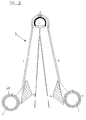
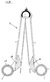
- the vertical guide for the displaceable mounting member consists of a paired arrangement of rods, pipes or ropes, the distance between which decreases with increasing height, and which cooperate with the displaceable mounting member so that the clamping force of the mounting member on the front wheel increases with increasing height.
- the mounting member is essentially formed by two gripping jaws, which are connected to one another at their front end by means of a hinge axis parallel to the guide and are guided along their rear end along one of the guide members, the guide being limited to a height corresponding to the bottom Radius of the front wheel of the bicycle.
- the bike can thus first be inserted between the open gripping jaws.
- the front wheel does not have to come to a standstill, but the horizontal retracting movement changes into the oblique or vertical movement in one go.
- the grip of the gripping member on the bicycle is indeed still relatively loose; At the beginning, however, this still loose grip is sufficient, since at the beginning there is little or no weight on the gripping element.
- the gripping jaws are pivoted towards one another by the mutually inclined guide members, and thus the front wheel is gripped more tightly, as does the weight, that is to say the required lifting force, increases.
- the bicycle can be brought into the stowed position solely with the physical strength of the user; but you can also provide a motor drive.
- the guide and the mounting member can be designed very differently, depending on the respective conditions and requirements.
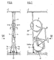
- a holding member or a gripper 5 is displaceable along the guide members 3, 4, which engages on the front part of the front wheel 6 of the bicycle in the direction of travel and transfers the bicycle into the vertical stowed position when displaced along the guide members 3, 4.
- the mounting member consists essentially of two gripping or clamping jaws 7, 8, which are connected at one end by means of a joint 9 which is substantially parallel to the guide, while their front ends are guided along the guide members.
- the clamping jaws each have at their end remote from the joint 9 a piece of pipe or a guide sleeve 10, 11, through which one of the guide members 3, 4 extends, and rolling elements are provided in between.
- the displacement path of the gripping jaws 7,8 is downward through the guide members 3, 4 fixed stops 12 limited approximately at the level of the front wheel axle.
- the inside of the gripping jaws are adapted to the cross-section of the tire and the rim of the bicycle.
- the distance between the guide members 3, 4 is dimensioned such that the front wheel 6 can be easily inserted between the open gripping jaws 7, 8 in the starting position according to FIGS. 1 and 2.
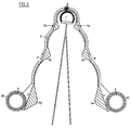
- the gripping jaws are expediently provided or padded with elastic material, as indicated in FIGS. 3 and 4 with 13, 14.
- the gripping jaws are expediently so elastic overall that they enclose the front wheel with resilient pressure.
- the front wheel is only gripped more tightly during the upward shift, while the handle is still relatively loose at the start of the shift; At the beginning, however, this still loose grip is sufficient, because at the beginning there is little or no weight on the gripping jaws.
- three different receptacles for three differently thick bicycle tires are provided on the two gripping jaws 7, 8, namely at the front, on the hinge axis 9 for a relatively thin one, then for a thick one and finally for one even thicker bicycle tires.
- These different receptacles are formed by corresponding bulges of the gripping jaws 7, 8 on the one hand and profiles or projections 13, 14 made of elastic material attached to their inner sides.
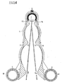
- the two guide members 3, 4 in their lower region 3 a, 4 a are more inclined towards one another and / or in the direction of travel, while the distance between them is further up Management bodies 3.4 decreases only slightly.
- This embodiment is particularly suitable if the gripping jaws 7, 8 are displaced by a special drive element, that is if the gripping jaws are not pushed up by the front wheel 6, but if, conversely, the gripping jaws 7, 8 follow the front wheel 6 and thus the bicycle as a whole pull up.
- a special rocker 17 is provided in front of and between the guide members 3, 4.
Landscapes
- Engineering & Computer Science (AREA)
- Mechanical Engineering (AREA)
- Steering Devices For Bicycles And Motorcycles (AREA)
- Liquid Crystal (AREA)
Applications Claiming Priority (2)
| Application Number | Priority Date | Filing Date | Title |
|---|---|---|---|
| DE4340215A DE4340215C1 (de) | 1993-11-25 | 1993-11-25 | Vorrichtung zur Halterung von Fahrrädern |
| DE4340215 | 1993-11-25 |
Publications (2)
| Publication Number | Publication Date |
|---|---|
| EP0655384A1 EP0655384A1 (de) | 1995-05-31 |
| EP0655384B1 true EP0655384B1 (de) | 1997-07-23 |
Family
ID=6503444
Family Applications (1)
| Application Number | Title | Priority Date | Filing Date |
|---|---|---|---|
| EP94118233A Expired - Lifetime EP0655384B1 (de) | 1993-11-25 | 1994-11-18 | Vorrichtung zur Halterung von Fahrrädern |
Country Status (4)
| Country | Link |
|---|---|
| EP (1) | EP0655384B1 (da) |
| AT (1) | ATE155753T1 (da) |
| DE (1) | DE4340215C1 (da) |
| DK (1) | DK655384T1 (da) |
Cited By (1)
| Publication number | Priority date | Publication date | Assignee | Title |
|---|---|---|---|---|
| DE102018116620A1 (de) | 2018-07-10 | 2020-01-16 | ROTARK GmbH | Fahrradgarage mit einer Hebehilfe |
Families Citing this family (3)
| Publication number | Priority date | Publication date | Assignee | Title |
|---|---|---|---|---|
| DE19734704A1 (de) * | 1997-07-04 | 1999-04-01 | Pitt Fischer | Fahrrad-Parkeinrichtung mit geringem Platzbedarf und Hebehilfe mittels Zug- oder Druckfedern |
| DE19830249C2 (de) * | 1998-07-07 | 2000-03-02 | Pitt Fischer | Vorrichtung zur Halterung von Fahrrädern in vertikaler Stellung |
| FR2909068B1 (fr) * | 2006-11-28 | 2009-07-17 | Guy Daudet | Dispositif de maintien d'une bicyclette en stationnement en position verticale ou proche |
Family Cites Families (9)
| Publication number | Priority date | Publication date | Assignee | Title |
|---|---|---|---|---|
| DE464279C (de) * | 1927-02-11 | 1928-08-14 | Eisenbau Maschf | Fahrradstaender |
| AT156188B (de) * | 1935-07-15 | 1939-05-25 | Josef Treiber Fa | Fahrradständer. |
| DE1020886B (de) * | 1955-04-12 | 1957-12-12 | Ubbo Wilhelm Groenendal | Fahrradparkvorrichtung |
| US3770133A (en) * | 1972-02-11 | 1973-11-06 | Miller E | Bicycle storage device |
| FR2546123A1 (fr) * | 1983-05-16 | 1984-11-23 | Decaux Jean Claude | Dispositif de parcage aerien de vehicules legers |
| DE4014158C2 (de) * | 1990-05-03 | 2003-11-27 | Oliver Wagener | Ortsfest installierte Vorrichtung zur Diebstahlsicherung eines Fahrrades |
| DE4119403A1 (de) * | 1991-06-10 | 1992-12-17 | Inst Schienenfahrzeuge | Fahrradstaender, insbesondere fuer eisenbahnwagen |
| DE4209007A1 (de) * | 1992-02-21 | 1993-08-26 | Gerhard Arnold | Wandhalter fuer ein fahrrad |
| DE9313401U1 (de) * | 1993-09-06 | 1994-01-13 | Arnold, Gerhard, 65187 Wiesbaden | Fahrradhalter |
-
1993
- 1993-11-25 DE DE4340215A patent/DE4340215C1/de not_active Expired - Fee Related
-
1994
- 1994-11-18 AT AT94118233T patent/ATE155753T1/de not_active IP Right Cessation
- 1994-11-18 EP EP94118233A patent/EP0655384B1/de not_active Expired - Lifetime
- 1994-11-18 DK DK94118233.9T patent/DK655384T1/da unknown
Cited By (2)
| Publication number | Priority date | Publication date | Assignee | Title |
|---|---|---|---|---|
| DE102018116620A1 (de) | 2018-07-10 | 2020-01-16 | ROTARK GmbH | Fahrradgarage mit einer Hebehilfe |
| DE102018116620B4 (de) * | 2018-07-10 | 2021-06-24 | ROTARK GmbH | Fahrradgarage mit einer Hebehilfe |
Also Published As
| Publication number | Publication date |
|---|---|
| DE4340215C1 (de) | 1995-01-26 |
| EP0655384A1 (de) | 1995-05-31 |
| DK655384T1 (da) | 1997-11-17 |
| ATE155753T1 (de) | 1997-08-15 |
Similar Documents
| Publication | Publication Date | Title |
|---|---|---|
| DE60318318T2 (de) | Lastträger zum transportieren eines fahrrads | |
| DE2658085C2 (de) | Beförderungsanlage mit seilgezogenen, spurgeführten Einzel-Wagen | |
| EP0655384B1 (de) | Vorrichtung zur Halterung von Fahrrädern | |
| DE102015004547A1 (de) | Vorrichtung zum Handantrieb des Vorderrades eines Fahrrades oder dgl. | |
| DE2805727C2 (de) | Stammvorschubgerät an einer Stammentästungsmaschine | |
| DE4027925A1 (de) | Muskelkraft-pedalantrieb zur umwandlung einer geradlinigen hin- und hergehenden, bzw. auf- und abgehenden bewegung in eine drehbewegung zum erreichen einer maximalen kraftuebertragung | |
| DE2262423C2 (de) | Blockiereinrichtung für einen Handwagen | |
| DE4431553B4 (de) | Fahrradhalter | |
| EP1600365B1 (de) | Motorradständer | |
| EP0329134B1 (de) | Verfahren und Vorrichtung zum Aufziehen eines Gleitschutzelementes, insbesondere eines Gleitschutzkette auf ein Kraftfahrzeugrad | |
| AT396743B (de) | Krankenfahrstuhl | |
| DE102004008451A1 (de) | Fahrzeuggegenstandsträger | |
| DE4235396C2 (de) | Seil-Fensterheber, insbesondere für Kraftfahrzeuge | |
| DE2727488A1 (de) | Bremseinheit | |
| DE4428714A1 (de) | Kupplungsvorrichtung für Zugmittel an einem Rollstuhl | |
| DE2930934C2 (de) | Parkvorrichtung für Kraftfahrzeuge | |
| EP0305636B1 (de) | Zusammenschiebbares Verdeck für Lastkraftwagen und Anhänger | |
| DE530693C (de) | Zusammenlegbares Fahrzeugverdeck | |
| DE2905773C2 (de) | Bremsbetätigungsvorrichtung für eine einachsige Handkarre | |
| DE4040240A1 (de) | Hebelkombination zur besseren kraftuebertragung | |
| DE1530321A1 (de) | Einrichtung zum Verschieben von Bahnwaggons | |
| DE202015002272U1 (de) | Vorrichtung zum Handantrieb des Vorderrades eines Fahrrades | |
| DE19945634C1 (de) | Hebevorrichtung | |
| DE3828580C2 (de) | Schiebevorrichtung für Förderwagen | |
| EP1620300B1 (de) | Wagenpulk |
Legal Events
| Date | Code | Title | Description |
|---|---|---|---|
| PUAI | Public reference made under article 153(3) epc to a published international application that has entered the european phase |
Free format text: ORIGINAL CODE: 0009012 |
|
| 17P | Request for examination filed |
Effective date: 19950320 |
|
| AK | Designated contracting states |
Kind code of ref document: A1 Designated state(s): AT CH DK ES FR GB IT LI NL |
|
| GRAG | Despatch of communication of intention to grant |
Free format text: ORIGINAL CODE: EPIDOS AGRA |
|
| GRAH | Despatch of communication of intention to grant a patent |
Free format text: ORIGINAL CODE: EPIDOS IGRA |
|
| 17Q | First examination report despatched |
Effective date: 19960418 |
|
| GRAH | Despatch of communication of intention to grant a patent |
Free format text: ORIGINAL CODE: EPIDOS IGRA |
|
| RAP1 | Party data changed (applicant data changed or rights of an application transferred) |
Owner name: SYMCON-MONTREUX S.A. |
|
| GRAA | (expected) grant |
Free format text: ORIGINAL CODE: 0009210 |
|
| AK | Designated contracting states |
Kind code of ref document: B1 Designated state(s): AT CH DK ES FR GB IT LI NL |
|
| PG25 | Lapsed in a contracting state [announced via postgrant information from national office to epo] |
Ref country code: IT Free format text: LAPSE BECAUSE OF FAILURE TO SUBMIT A TRANSLATION OF THE DESCRIPTION OR TO PAY THE FEE WITHIN THE PRE;WARNING: LAPSES OF ITALIAN PATENTS WITH EFFECTIVE DATE BEFORE 2007 MAY HAVE OCCURRED AT ANY TIME BEFORE 2007. THE CORRECT EFFECTIVE DATE MAY BE DIFFERENT FROM THE ONE RECORDED.SCRIBED TIME-LIMIT Effective date: 19970723 Ref country code: ES Free format text: THE PATENT HAS BEEN ANNULLED BY A DECISION OF A NATIONAL AUTHORITY Effective date: 19970723 |
|
| REF | Corresponds to: |
Ref document number: 155753 Country of ref document: AT Date of ref document: 19970815 Kind code of ref document: T |
|
| REG | Reference to a national code |
Ref country code: CH Ref legal event code: EP |
|
| ET | Fr: translation filed | ||
| GBT | Gb: translation of ep patent filed (gb section 77(6)(a)/1977) |
Effective date: 19971010 |
|
| PGFP | Annual fee paid to national office [announced via postgrant information from national office to epo] |
Ref country code: DK Payment date: 19971128 Year of fee payment: 4 |
|
| REG | Reference to a national code |
Ref country code: DK Ref legal event code: T3 |
|
| PGFP | Annual fee paid to national office [announced via postgrant information from national office to epo] |
Ref country code: AT Payment date: 19980220 Year of fee payment: 4 |
|
| PLBE | No opposition filed within time limit |
Free format text: ORIGINAL CODE: 0009261 |
|
| STAA | Information on the status of an ep patent application or granted ep patent |
Free format text: STATUS: NO OPPOSITION FILED WITHIN TIME LIMIT |
|
| 26N | No opposition filed | ||
| REG | Reference to a national code |
Ref country code: FR Ref legal event code: ST |
|
| PG25 | Lapsed in a contracting state [announced via postgrant information from national office to epo] |
Ref country code: DK Free format text: LAPSE BECAUSE OF NON-PAYMENT OF DUE FEES Effective date: 19981118 Ref country code: AT Free format text: LAPSE BECAUSE OF NON-PAYMENT OF DUE FEES Effective date: 19981118 |
|
| REG | Reference to a national code |
Ref country code: FR Ref legal event code: RN |
|
| REG | Reference to a national code |
Ref country code: FR Ref legal event code: FC |
|
| PGFP | Annual fee paid to national office [announced via postgrant information from national office to epo] |
Ref country code: CH Payment date: 19990218 Year of fee payment: 5 |
|
| PGFP | Annual fee paid to national office [announced via postgrant information from national office to epo] |
Ref country code: NL Payment date: 19991123 Year of fee payment: 6 |
|
| PGFP | Annual fee paid to national office [announced via postgrant information from national office to epo] |
Ref country code: FR Payment date: 19991124 Year of fee payment: 6 |
|
| PGFP | Annual fee paid to national office [announced via postgrant information from national office to epo] |
Ref country code: GB Payment date: 19991126 Year of fee payment: 6 |
|
| PG25 | Lapsed in a contracting state [announced via postgrant information from national office to epo] |
Ref country code: LI Free format text: LAPSE BECAUSE OF NON-PAYMENT OF DUE FEES Effective date: 19991130 Ref country code: CH Free format text: LAPSE BECAUSE OF NON-PAYMENT OF DUE FEES Effective date: 19991130 |
|
| REG | Reference to a national code |
Ref country code: CH Ref legal event code: PL |
|
| REG | Reference to a national code |
Ref country code: DK Ref legal event code: EBP |
|
| PG25 | Lapsed in a contracting state [announced via postgrant information from national office to epo] |
Ref country code: GB Free format text: LAPSE BECAUSE OF NON-PAYMENT OF DUE FEES Effective date: 20001118 |
|
| PG25 | Lapsed in a contracting state [announced via postgrant information from national office to epo] |
Ref country code: NL Free format text: LAPSE BECAUSE OF NON-PAYMENT OF DUE FEES Effective date: 20010601 |
|
| GBPC | Gb: european patent ceased through non-payment of renewal fee |
Effective date: 20001118 |
|
| PG25 | Lapsed in a contracting state [announced via postgrant information from national office to epo] |
Ref country code: FR Free format text: LAPSE BECAUSE OF NON-PAYMENT OF DUE FEES Effective date: 20010731 |
|
| NLV4 | Nl: lapsed or anulled due to non-payment of the annual fee |
Effective date: 20010601 |
|
| REG | Reference to a national code |
Ref country code: FR Ref legal event code: ST |