EP0654645A2 - Echangeur de chaleur - Google Patents
Echangeur de chaleur Download PDFInfo
- Publication number
- EP0654645A2 EP0654645A2 EP94308661A EP94308661A EP0654645A2 EP 0654645 A2 EP0654645 A2 EP 0654645A2 EP 94308661 A EP94308661 A EP 94308661A EP 94308661 A EP94308661 A EP 94308661A EP 0654645 A2 EP0654645 A2 EP 0654645A2
- Authority
- EP
- European Patent Office
- Prior art keywords
- heat exchanger
- tubes
- tube
- straight sections
- bent
- Prior art date
- Legal status (The legal status is an assumption and is not a legal conclusion. Google has not performed a legal analysis and makes no representation as to the accuracy of the status listed.)
- Granted
Links
Images


Classifications
-
- F—MECHANICAL ENGINEERING; LIGHTING; HEATING; WEAPONS; BLASTING
- F28—HEAT EXCHANGE IN GENERAL
- F28F—DETAILS OF HEAT-EXCHANGE AND HEAT-TRANSFER APPARATUS, OF GENERAL APPLICATION
- F28F9/00—Casings; Header boxes; Auxiliary supports for elements; Auxiliary members within casings
- F28F9/02—Header boxes; End plates
- F28F9/026—Header boxes; End plates with static flow control means, e.g. with means for uniformly distributing heat exchange media into conduits
- F28F9/027—Header boxes; End plates with static flow control means, e.g. with means for uniformly distributing heat exchange media into conduits in the form of distribution pipes
- F28F9/0273—Header boxes; End plates with static flow control means, e.g. with means for uniformly distributing heat exchange media into conduits in the form of distribution pipes with multiple holes
-
- F—MECHANICAL ENGINEERING; LIGHTING; HEATING; WEAPONS; BLASTING
- F28—HEAT EXCHANGE IN GENERAL
- F28D—HEAT-EXCHANGE APPARATUS, NOT PROVIDED FOR IN ANOTHER SUBCLASS, IN WHICH THE HEAT-EXCHANGE MEDIA DO NOT COME INTO DIRECT CONTACT
- F28D1/00—Heat-exchange apparatus having stationary conduit assemblies for one heat-exchange medium only, the media being in contact with different sides of the conduit wall, in which the other heat-exchange medium is a large body of fluid, e.g. domestic or motor car radiators
- F28D1/02—Heat-exchange apparatus having stationary conduit assemblies for one heat-exchange medium only, the media being in contact with different sides of the conduit wall, in which the other heat-exchange medium is a large body of fluid, e.g. domestic or motor car radiators with heat-exchange conduits immersed in the body of fluid
- F28D1/04—Heat-exchange apparatus having stationary conduit assemblies for one heat-exchange medium only, the media being in contact with different sides of the conduit wall, in which the other heat-exchange medium is a large body of fluid, e.g. domestic or motor car radiators with heat-exchange conduits immersed in the body of fluid with tubular conduits
- F28D1/047—Heat-exchange apparatus having stationary conduit assemblies for one heat-exchange medium only, the media being in contact with different sides of the conduit wall, in which the other heat-exchange medium is a large body of fluid, e.g. domestic or motor car radiators with heat-exchange conduits immersed in the body of fluid with tubular conduits the conduits being bent, e.g. in a serpentine or zig-zag
- F28D1/0475—Heat-exchange apparatus having stationary conduit assemblies for one heat-exchange medium only, the media being in contact with different sides of the conduit wall, in which the other heat-exchange medium is a large body of fluid, e.g. domestic or motor car radiators with heat-exchange conduits immersed in the body of fluid with tubular conduits the conduits being bent, e.g. in a serpentine or zig-zag the conduits having a single U-bend
- F28D1/0476—Heat-exchange apparatus having stationary conduit assemblies for one heat-exchange medium only, the media being in contact with different sides of the conduit wall, in which the other heat-exchange medium is a large body of fluid, e.g. domestic or motor car radiators with heat-exchange conduits immersed in the body of fluid with tubular conduits the conduits being bent, e.g. in a serpentine or zig-zag the conduits having a single U-bend the conduits having a non-circular cross-section
-
- F—MECHANICAL ENGINEERING; LIGHTING; HEATING; WEAPONS; BLASTING
- F28—HEAT EXCHANGE IN GENERAL
- F28F—DETAILS OF HEAT-EXCHANGE AND HEAT-TRANSFER APPARATUS, OF GENERAL APPLICATION
- F28F1/00—Tubular elements; Assemblies of tubular elements
- F28F1/02—Tubular elements of cross-section which is non-circular
- F28F1/025—Tubular elements of cross-section which is non-circular with variable shape, e.g. with modified tube ends, with different geometrical features
-
- F—MECHANICAL ENGINEERING; LIGHTING; HEATING; WEAPONS; BLASTING
- F28—HEAT EXCHANGE IN GENERAL
- F28F—DETAILS OF HEAT-EXCHANGE AND HEAT-TRANSFER APPARATUS, OF GENERAL APPLICATION
- F28F9/00—Casings; Header boxes; Auxiliary supports for elements; Auxiliary members within casings
- F28F9/001—Casings in the form of plate-like arrangements; Frames enclosing a heat exchange core
-
- F—MECHANICAL ENGINEERING; LIGHTING; HEATING; WEAPONS; BLASTING
- F28—HEAT EXCHANGE IN GENERAL
- F28F—DETAILS OF HEAT-EXCHANGE AND HEAT-TRANSFER APPARATUS, OF GENERAL APPLICATION
- F28F9/00—Casings; Header boxes; Auxiliary supports for elements; Auxiliary members within casings
- F28F9/02—Header boxes; End plates
-
- F—MECHANICAL ENGINEERING; LIGHTING; HEATING; WEAPONS; BLASTING
- F28—HEAT EXCHANGE IN GENERAL
- F28F—DETAILS OF HEAT-EXCHANGE AND HEAT-TRANSFER APPARATUS, OF GENERAL APPLICATION
- F28F9/00—Casings; Header boxes; Auxiliary supports for elements; Auxiliary members within casings
- F28F9/26—Arrangements for connecting different sections of heat-exchange elements, e.g. of radiators
- F28F9/262—Arrangements for connecting different sections of heat-exchange elements, e.g. of radiators for radiators
-
- F—MECHANICAL ENGINEERING; LIGHTING; HEATING; WEAPONS; BLASTING
- F28—HEAT EXCHANGE IN GENERAL
- F28D—HEAT-EXCHANGE APPARATUS, NOT PROVIDED FOR IN ANOTHER SUBCLASS, IN WHICH THE HEAT-EXCHANGE MEDIA DO NOT COME INTO DIRECT CONTACT
- F28D21/00—Heat-exchange apparatus not covered by any of the groups F28D1/00 - F28D20/00
- F28D2021/0019—Other heat exchangers for particular applications; Heat exchange systems not otherwise provided for
- F28D2021/008—Other heat exchangers for particular applications; Heat exchange systems not otherwise provided for for vehicles
- F28D2021/0084—Condensers
-
- F—MECHANICAL ENGINEERING; LIGHTING; HEATING; WEAPONS; BLASTING
- F28—HEAT EXCHANGE IN GENERAL
- F28D—HEAT-EXCHANGE APPARATUS, NOT PROVIDED FOR IN ANOTHER SUBCLASS, IN WHICH THE HEAT-EXCHANGE MEDIA DO NOT COME INTO DIRECT CONTACT
- F28D21/00—Heat-exchange apparatus not covered by any of the groups F28D1/00 - F28D20/00
- F28D2021/0019—Other heat exchangers for particular applications; Heat exchange systems not otherwise provided for
- F28D2021/008—Other heat exchangers for particular applications; Heat exchange systems not otherwise provided for for vehicles
- F28D2021/0085—Evaporators
Definitions
- the present invention relates to a heat exchanger that is adapted for use as an evaporator, a condenser or the like in car air-conditioners, room air-conditioners or the like, and more particularly relates to a heat exchanger comprising heat exchanging tubes which are bent at their intermediate portions between opposite ends.
- the heat exchangers recently used in the car air-conditioners are of the so-called multi-flow or parallel flow type.
- Flat and straight tubes are arranged at regular intervals and in parallel with and spaced apart from each other a predetermined distance in the direction of their thickness. Both the opposite ends of each tube are connected to a pair of hollow headers, in fluid communication therewith.
- heat exchanger of this type heat exchange occurs between a medium flowing through the tubes and air streams flowing through air paths each defined between the adjacent tubes.
- a certain improved heat exchanger is proposed for example in the Japanese Unexamined Patent Publication No. 63-282490. This type is improved in the efficiency of heat exchange and in the drainage of condensed dew, and is of a decreased dimension to fit in a narrower space.
- Each flat tube in the heat exchanger of this type has, intermediate its opposite ends, a middle portion bent in the direction of its width.
- An object of the present invention made in view of the described problems inherent in the prior art is therefore to provide a heat exchanger comprising a plurality of flat tubes arranged at regular intervals and in parallel with and spaced apart from each other a predetermined distance in the direction of thickness of the tubes, both the opposite ends of each tube being connected to a pair of headers in fluid communication therewith, wherein the tubes are bent at their intermediate portions in the direction of their width in such a manner that the heat exchanger is easy to manufacture, pressure loss of a heat exchanging medium flowing therethrough is suppressed, and heat exchange efficiency thereof is improved.
- the heat exchanger comprises: a plurality of flat tubes arranged at regular intervals and in parallel with and spaced apart from each other a predetermined distance in the direction of thickness of the tubes; a pair of hollow headers disposed at one ends and other ends of the tubes, which are connected thereto in fluid communication therewith; each tube having an intermediate bent portion and straight sections separated one from another by the bent portion; the bent portion being a portion of each tube twisted at a predetermined helical angle; and fins each interposed between the adjacent straight sections.
- it may further comprise: additional fins disposed outside the outermost tubes; and reinforcing strips each composed of a middle section and end sections continuing therefrom.
- the middle section has formed therethrough apertures each fitting on a boundary present between the straight section and the twisted bent portion of each tube, and each end section of the reinforcing strip extending along and fixedly adjoined to the outer surface of the corresponding additional fin.
- the twisted and bent portions located adjacent to each other may contact and overlap one another to reinforce said portions as a whole.
- each bent portion is twisted at a predetermined helical angle relative to the adjacent straight sections.
- the flat and straight tubes arranged parallel at regular intervals and each having opposite ends connected to the headers in fluid communication therewith may be bent all at once in the direction of tubes' width.
- Each portion which is being bent between the straight sections will simultaneously and spontaneously be twisted relative thereto.
- the twisted and bent portions can now be formed very easily, without encountering any technical difficulty.
- the heat exchanger comprises the aforementioned reinforcing strips each composed of the middle section and the end sections continuing therefrom and formed perpendicular thereto, the straight sections are protected from deformation during the bending-and-twisting operation. This is because a stress imparted to the tubes which are being bent is restricted to their middle portions located between the middle sections of said strips, even if each tube is forced to have a considerably small radius of curvature.
- the reinforcing strips thus contribute not only to an easier manufacture but also to an improved overall strength of the heat exchanger.
- the overlapping of the adjacent bent portions will further improve their strength as a whole.
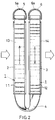
- a heat exchanger which Figs. 1 to 16 illustrate is an evaporator provided in the first embodiment for use in a car air conditioner.
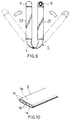
- Each of flat heat exchanging tubes 1 shown in Fig. 1 is of an elliptic shape in cross section and has an upper and lower flat walls 1a. Those flat walls la are connected one to another by a few connecting walls 1b so that several unit paths 1c are defined in and longitudinally of the tube, as seen in Fig. 10.
- the tubes 1 are aluminum extruded pieces of the so-called harmonica structure in this embodiment. However, they may be flat seam-welded tubes having inserted therein internal corrugated fins, or of any other conventional structure in the present invention.
- Each of the flat tubes 1 shown in Figs. 1 and 2 has straight sections 2 and 3 and a middle portion 4 integral with and intervening between them.
- This middle portion 4 is bent and twisted to have a predetermined helical angle relative to the straight sections.
- the bent and twisted middle portion 4 is generally U-shaped such that the straight sections 2 and 3 of each tube extend in parallel with each other and are included in a common plane.
- the tube 1 may not be bent into a U-shape but into a V-shape or the like such that the straight sections 2 and 3 extend at a predetermined angle relative to each other. Further, the bent and twisted portion 4 may not necessarily be positioned right in the middle of each tube.
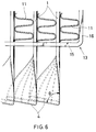
- An outer edge of the bent and twisted portion 4 lies almost in parallel with the straight sections 2 and 3, as shown in Fig. 6.
- a helical angle ⁇ defined between the bent portion and each straight section is predetermined to be slightly smaller than 90°.
- bent portion 4 preferably of a smooth and arcuate contour is usually designed as short as the torsional strength allows. Any specific configuration and radius of curvature may be employed so long as the internal flow path of tube substantially remains non-collapsed and has an unconstricted cross-sectional area.
- the generally U-shaped flat tubes 1 having at their bottoms the bent and twisted portions 4 are arranged such that their vertical straight sections 2 and 3 are located side by side and at regular intervals.
- Aluminum hollow headers 5 and 6 are connected to upper ends of the flat tubes.
- the bent portions 4 of the adjacent tubes 1 overlap and fit on each other so as to support one another and improve their strength. Those bent portions may be brazed or otherwise secured one to another to further raise the strength.
- Fins such as aluminum corrugated fins 11 are disposed between the adjacent straight sections 2 located windward and also outside the outermost straight sections 2. Similar fins 12 are disposed between the adjacent straight sections 3 located leeward and also outside the outermost straight sections 3. Those fins are brazed to the straight sections 2 and 3. Fin pitch of the windward fins 11 is greater than that of the leeward ones 12.
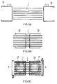
- a front reinforcing strip 13 is secured to and surrounds the group of windward straight sections 2, while a rear reinforcing strip 14 being likewise secured to and surrounding the group of leeward straight sections 3.
- Each reinforcing strip is made by bending an elongate plate, and has a middle section 15 and end sections 16 bent upward and extending therefrom so that it assumes a U-shape in front elevation.
- apertures 15a are formed through the middle section 15 at a pitch corresponding to the flat tubes 1.
- a boundary between the bent portion and the straight section 2 or 3 is brazed to and held in the corresponding aperture 15a in which the tube 1 is inserted.
- each of the end sections 16 is in contact with and brazed to the fin 11 or 12 which is located outside the outermost tube 1. It is preferable that, in order to facilitate the brazing process, the reinforcing strips are made of a sheet which is composed of a core having either or both surfaces clad with a brazing agent layer.
- the reinforcing strips 13 and 14 which contribute to an improved strength of the core of this heat exchanger, circumscribe the bending and twisting action within narrow bounds.
- the tubes' straight sections are thus protected from any torsion or bending.
- each reinforcing strip 13 and 14 may have drainage holes 15b formed therethrough and/or drainage trough portions 15c, as shown in Fig. 13, which will prevent stagnation of the condensed water.
- the headers 5 and 6 are made of an aluminum brazing sheet composed of a core which has either or both sides clad with a brazing agent layer. In manufacture, the brazing sheet is rolled into a cylinder having abutment edges which are subsequently seam welded.
- Each header has a cross section of generally 'laid-down D-shape' such that a flat bottom receiving the tubes continues to an arcuate dome, as seen in Fig. 2. Although this shape may be somewhat inferior to a circular cross section in respect of resistance to a high internal pressure such as operating in condensers, those headers can withstand well a medium internal pressure operating in evaporators.
- Such a specific cross-sectional shape of the headers is advantageous in that ends of each tube 1 need not be inserted so deep as to reach an axis of the header, contrary to the case of using headers of a circular cross section.
- an effective length of each tube 1 is made greater to thereby increase the effective area of the core.
- the headers 5 and 6 may have a cross section composed of a semi-ellipse and a semicircle, with the former receiving the tube ends as shown in Fig. 11. This modification will also be advantageous from the viewpoint as mentioned above.
- Fig. 12 shows baffles 10 each secured to a part of cylindrical wall of each header 5 or 6, wherein the part is opposite to another part in which the tubes 1 are secured.
- Each baffle 10 is located between the adjacent tubes and comprises a base 10a and a leg 10b. This leg 10b protrudes inwardly towards the tubes' ends so that the heat exchanging medium is smoothly and evenly distributed into the tubes.
- the base 10a is fixed to an outer peripheral surface of the header 5 or 6.
- the heat exchanging medium will flow into a leeward one of the headers 6 through an inlet pipe 7 liquid-tightly connected thereto. Tributaries of the medium will flow through the respective tubes 1, each making a U-turn to enter the windward header 5, as indicated at the arrows in Fig. 1.
- the tributaries through the tubes 1 join one another in the windward header and leave it through an outlet pipe 8, after heat exchange has been effected between the medium and air streams penetrating this heat exchanger from front to rear as shown by the white arrows.
- the inlet pipe 7 and outlet pipe 8 may be attached to the headers at their ends located side by side, as shown in Fig. 14, so that the heat exchanging medium can flow into and out of the same side end of the heat exchanger. Further, an internal pipe 60 having small holes 60a corresponding to the tubes may be secured in and coaxially of the inlet side (viz. leeward) header 6. Such an internal pipe connected to the inlet pipe 7 will ensure an even distribution of the heat exchanging medium into the tubes.
- the described heat exchanger may be manufactured, for example in the following manner.
- each tube 1 is bent at its middle portion in the direction of its thickness, so that its straight sections lie in parallel with each other, as shown in Fig. 9. It may be preferable to use a proper tool to give all the middle portions a slight pretwist which will allow them to readily twist in the same direction.
- the tubes 1 can easily be twisted in the direction of their width, at any predetermined middle portions 4 and at a predetermined helical angle relative to their straight sections, whether pretwisted to any extent or not.
- the pitch of windward fins 11 is designed larger than that of leeward ones 12 so that a satisfactory performance is afforded as to the heat exchange.
- the coolant flowing into the leeward header 6 is distributed to all the tubes forming tributaries connected thereto. Those tributaries join one another in harmony in the windward header 5 to construct the so-called 'one pass' system. Partitions may be secured in the headers 5 and 6, if necessary, to form 'plural passes' which cause the heat exchanging medium to meander through the heat exchanger.
- Samples of heat exchangers were prepared, which each comprised a core 235 mm high and 258 mm wide so that an effective size of the core was 178 mmH x 259 mmW.
- the tube pitch was set at 11.7 mm, with the number of tubes being 21, each fin being 22 mm wide and 10 mm high, and fin pitch being 1.1 mm.
- One of the sample heat exchangers was of the 'two pass' type, having the partitions dividing the tubes into a first group of 10 tubes and a second group of 11 tubes.
- Fig. 15 shows a relationship observed between the heat rejection (kcal/h) and the medium pressure at outlet (kg/cm2).
- Fig. 16 shows another relationship observed between the pressure loss of the medium (kg/cm2) and the flow rate thereof (kg/h).
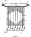
- Fig. 17 to 21 illustrate the second embodiment of the present invention also applied to an evaporator for use in car air conditioners.
- This evaporator is of a structure almost similar to that provided in the first embodiment, but different therefrom in: the cross-sectional shape of headers; the reinforcing strips dispensed with; and the configuration of the tubes' bent and twisted portions. Such differences will be briefed below.
- each bent and twisted portion 4 of the tubes 1 lies at 90°, viz. perpendicular, to the straight sections 2 and 3 thereof.
- the adjacent bent portions 4 do not overlap one another, as seen in Fig. 17.
- the headers 5 and 6 are of a round cross section to raise their pressure resistance.
- the heat exchanger in the second embodiment does not comprise any reinforcing strips.
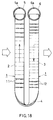
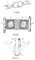
- the tubes 1 are preliminarily twisted at first at their middle portions as shown in Fig. 19, before assembled into a state shown in Fig. 20 and subsequently bent in a manner shown in Fig. 21 to provide a finished heat exchanger. It may be possible to twist and simultaneously bent those tubes, also in the second embodiment.
- a condenser provided in the third embodiment is for use in car air conditioners.
- This condenser differs from the evaporators provided in the first embodiment only in that: the headers 5 and 6 stand upright; the straight sections 2 and 3 of each tube 1 are disposed horizontally; each header is of a round cross section; and the partitioning members inserted in headers.
- the round headers 5 and 6 are adapted for an internal pressure higher than that operating in the evaporators.
- Each of the partitioning members 20 shown in Fig. 22 divides the interior of header 5 or 6 into longitudinal compartments arranged in a head-to-tail relationship, so that a heat exchanging medium meanders through this condenser.
- each flat tube has its middle portion that is located intermediate its straight sections, bent in the direction of the tube's width and twisted at a predetermined angle relative to the straight sections.
- the heat exchanger comprises the aforementioned reinforcing strips each composed of the middle section and the end sections continuing therefrom and formed perpendicular thereto, the straight sections are protected from deformation during the bending-and-twisting operation. This is because a stress imparted to the tubes which are being bent is restricted to their middle portions located between the middle sections of said strips, even if each tube is forced to have a considerably small radius of curvature.
- the reinforcing strips thus contribute not only to an easier manufacture but also to an improved overall strength of the heat exchanger.
- the overlapping of the adjacent bent portions will further improve their strength as a whole.
Applications Claiming Priority (2)
| Application Number | Priority Date | Filing Date | Title |
|---|---|---|---|
| JP293439/93 | 1993-11-24 | ||
| JP29343993A JP3305460B2 (ja) | 1993-11-24 | 1993-11-24 | 熱交換器 |
Publications (3)
| Publication Number | Publication Date |
|---|---|
| EP0654645A2 true EP0654645A2 (fr) | 1995-05-24 |
| EP0654645A3 EP0654645A3 (fr) | 1995-11-02 |
| EP0654645B1 EP0654645B1 (fr) | 1999-01-07 |
Family
ID=17794782
Family Applications (1)
| Application Number | Title | Priority Date | Filing Date |
|---|---|---|---|
| EP94308661A Expired - Lifetime EP0654645B1 (fr) | 1993-11-24 | 1994-11-23 | Echangeur de chaleur |
Country Status (9)
| Country | Link |
|---|---|
| US (1) | US5531268A (fr) |
| EP (1) | EP0654645B1 (fr) |
| JP (1) | JP3305460B2 (fr) |
| KR (1) | KR100335872B1 (fr) |
| CN (1) | CN1074526C (fr) |
| AT (1) | ATE175492T1 (fr) |
| AU (1) | AU678620B2 (fr) |
| DE (1) | DE69415779T2 (fr) |
| ES (1) | ES2127358T3 (fr) |
Cited By (26)
| Publication number | Priority date | Publication date | Assignee | Title |
|---|---|---|---|---|
| DE19830863A1 (de) * | 1998-07-10 | 2000-01-13 | Behr Gmbh & Co | Flachrohr mit Querversatz-Umkehrbogenabschnitt und damit aufgebauter Wärmeübertrager |
| FR2793013A1 (fr) * | 1999-04-28 | 2000-11-03 | Valeo Thermique Moteur Sa | Echangeur de chaleur brase, en particulier pour vehicule automobile |
| AU740183B2 (en) * | 1999-05-31 | 2001-11-01 | Mitsubishi Heavy Industries, Ltd. | Heat exchanger |
| EP1231448A2 (fr) * | 2001-02-07 | 2002-08-14 | Modine Manufacturing Company | Echangeur de chaleur |
| WO2004005826A1 (fr) * | 2002-07-03 | 2004-01-15 | Behr Gmbh & Co. | Echangeur de chaleur |
| DE10241635A1 (de) * | 2001-10-02 | 2004-02-05 | Behr Gmbh & Co. | Flachrohr-Wärmeübertrager sowie Herstellungsverfahren hierfür |
| EP1397623A1 (fr) * | 2001-06-18 | 2004-03-17 | Showa Dendo K.K. | Evaporateur, procede de fabrication afferent, collecteur pour ledit evaporateur et systeme de refrigeration |
| KR20040038328A (ko) * | 2002-10-31 | 2004-05-08 | 엘지전자 주식회사 | 열교환기의 연결 장치 |
| EP1452814A1 (fr) * | 2001-11-08 | 2004-09-01 | Zexel Valeo Climate Control Corporation | Echangeur thermique et tube pour echangeur thermique |
| GB2400648A (en) * | 2003-03-19 | 2004-10-20 | Calsonic Kansei Uk Ltd | An automotive heat exchanger |
| WO2004074756A3 (fr) * | 2003-02-18 | 2004-10-21 | Behr Gmbh & Co Kg | Tube plat presentant une section coudee en u et echangeur thermique comportant un tel tube plat |
| FR2907887A1 (fr) * | 2006-10-25 | 2008-05-02 | Valeo Systemes Thermiques | Echangeur de chaleur protege vis-a-vis des ponts thermiques et procede de fabrication d'un tel echangeur |
| WO2008058734A1 (fr) * | 2006-11-15 | 2008-05-22 | Behr Gmbh & Co. Kg | Échangeur de chaleur |
| WO2008064251A2 (fr) * | 2006-11-22 | 2008-05-29 | Johnson Controls Technology Company | Échangeur thermique multicanaux compact |
| WO2009018159A2 (fr) * | 2007-07-27 | 2009-02-05 | Johnson Controls Technology Company | Echangeur thermique multicanaux multi-tranches |
| US7942020B2 (en) | 2007-07-27 | 2011-05-17 | Johnson Controls Technology Company | Multi-slab multichannel heat exchanger |
| CN101850391B (zh) * | 2009-03-31 | 2012-07-04 | 三花丹佛斯(杭州)微通道换热器有限公司 | 扁管加工方法及扁管、热交换器加工方法及热交换器 |
| DE202013101092U1 (de) | 2012-03-14 | 2013-07-02 | Valmex S.P.A. | Wärmeübertrager, der sich besonders zur Verwendung als Verdampfer eignet |
| EP2865982A4 (fr) * | 2012-04-26 | 2016-03-30 | Mitsubishi Electric Corp | Echangeur de chaleur et dispositif à cycle réfrigérant équipé de l'échangeur de chaleur |
| WO2016081306A1 (fr) * | 2014-11-17 | 2016-05-26 | Carrier Corporation | Échangeur de chaleur à micro-canaux plié à passages multiples et plaques multiples |
| KR20160116888A (ko) * | 2015-03-31 | 2016-10-10 | 한국교통대학교산학협력단 | 리턴캡을 이용한 열교환기 및 그 열교환기를 이용한 열교환방법 |
| EP2378232A3 (fr) * | 2010-04-13 | 2017-04-19 | Sanhua (Hangzhou) Micro Channel Heat Exchanger Co., Ltd. | Échangeur thermique à micro-canal incurvé |
| EP2671032B1 (fr) | 2011-02-04 | 2018-05-09 | MAHLE Behr GmbH & Co. KG | Échangeur de chaleur |
| RU2693946C2 (ru) * | 2014-11-26 | 2019-07-08 | Кэрриер Корпорейшн | Стойкий к образованию инея микроканальный теплообменник |
| WO2020081389A1 (fr) * | 2018-10-18 | 2020-04-23 | Carrier Corporation | Support supporté par un tube d'échangeur de chaleur à microcanaux |
| US11982491B2 (en) | 2019-10-11 | 2024-05-14 | Carrier Corporation | Microchannel heat exchanger tube supported bracket |
Families Citing this family (82)
| Publication number | Priority date | Publication date | Assignee | Title |
|---|---|---|---|---|
| KR100532187B1 (ko) * | 1998-11-28 | 2006-02-08 | 한라공조주식회사 | 증발기 |
| DE19859756B4 (de) * | 1998-12-23 | 2007-04-19 | Behr Gmbh & Co. Kg | Wärmetauscher |
| JP4632273B2 (ja) * | 2000-04-18 | 2011-02-16 | ティーエス ヒートロニクス 株式会社 | ヒートシンク及びその製造方法 |
| TW475052B (en) * | 2001-07-18 | 2002-02-01 | Chiun-Yau Jeng | Heat-dissipating blade device |
| US6830100B2 (en) * | 2001-11-02 | 2004-12-14 | Thermalex, Inc. | Extruded manifold |
| DE10158436A1 (de) * | 2001-11-29 | 2003-06-12 | Behr Gmbh & Co | Wärmetauscher |
| US20030102113A1 (en) * | 2001-11-30 | 2003-06-05 | Stephen Memory | Heat exchanger for providing supercritical cooling of a working fluid in a transcritical cooling cycle |
| US20030106677A1 (en) * | 2001-12-12 | 2003-06-12 | Stephen Memory | Split fin for a heat exchanger |
| BR0215235A (pt) * | 2001-12-21 | 2004-11-16 | Behr Gmbh & Co Kg | Trocador de calor, especialmente para um automóvel |
| WO2004013558A2 (fr) * | 2002-07-26 | 2004-02-12 | Behr Gmbh & Co. | Dispositif d'echange de chaleur |
| DE10237648A1 (de) * | 2002-08-13 | 2004-02-26 | Behr Gmbh & Co. | Wärmeübertrager |
| FR2847973B1 (fr) * | 2002-11-29 | 2006-01-27 | Valeo Climatisation | Echangeur de chaleur a inertie thermique pour circuit de fluide caloporteur, notamment de vehicule automobile. |
| DE102004018317A1 (de) * | 2004-04-13 | 2005-11-03 | Behr Gmbh & Co. Kg | Wärmeübertrager für Kraftfahrzeuge |
| US7281387B2 (en) * | 2004-04-29 | 2007-10-16 | Carrier Commercial Refrigeration Inc. | Foul-resistant condenser using microchannel tubing |
| JP2005321151A (ja) * | 2004-05-10 | 2005-11-17 | Sanden Corp | 熱交換器 |
| US7104314B2 (en) * | 2004-06-29 | 2006-09-12 | Modine Manufacturing Company | Multi-pass heat exchanger |
| EP1844285A4 (fr) * | 2005-02-02 | 2011-12-21 | Carrier Corp | Echangeur thermique a tubes plats multicanaux |
| US20070000652A1 (en) * | 2005-06-30 | 2007-01-04 | Ayres Steven M | Heat exchanger with dimpled tube surfaces |
| US20070114005A1 (en) * | 2005-11-18 | 2007-05-24 | Matthias Bronold | Heat exchanger assembly for fuel cell and method of cooling outlet stream of fuel cell using the same |
| JP2008045862A (ja) * | 2006-08-21 | 2008-02-28 | Daikin Ind Ltd | 熱交換器および熱交換器の製造方法 |
| JP2008122058A (ja) * | 2006-10-17 | 2008-05-29 | Alps Electric Co Ltd | ラジエータ及び冷却システム |
| US7921904B2 (en) * | 2007-01-23 | 2011-04-12 | Modine Manufacturing Company | Heat exchanger and method |
| JP2009216315A (ja) * | 2008-03-11 | 2009-09-24 | Showa Denko Kk | 熱交換器 |
| US20110094257A1 (en) * | 2008-03-20 | 2011-04-28 | Carrier Corporation | Micro-channel heat exchanger suitable for bending |
| JP5444782B2 (ja) * | 2008-09-12 | 2014-03-19 | 株式会社デンソー | 蓄冷熱交換器 |
| CN101806550B (zh) * | 2010-03-24 | 2014-02-19 | 三花控股集团有限公司 | 微通道换热器 |
| CN101890446B (zh) * | 2010-07-28 | 2012-07-18 | 三花丹佛斯(杭州)微通道换热器有限公司 | 换热器折弯方法和换热器折弯工具 |
| DE102010032899A1 (de) * | 2010-07-30 | 2012-02-02 | Valeo Klimasysteme Gmbh | Kühlvorrichtung für eine Fahrzeugbatterie sowie Fahrzeugbatteriebaugruppe mit einer solchen Kühlvorrichtung |
| CN101936672B (zh) * | 2010-09-15 | 2012-09-19 | 三花控股集团有限公司 | 具有改善的表面空气流场分布均匀性的换热器 |
| CN102330719A (zh) * | 2011-07-29 | 2012-01-25 | 烟台富耐克散热器有限公司 | 管带式油散热器 |
| WO2013058953A1 (fr) | 2011-10-19 | 2013-04-25 | Carrier Corporation | Echangeur de chaleur à ailettes en tube aplati et procédé de fabrication |
| US9689594B2 (en) | 2012-07-09 | 2017-06-27 | Modine Manufacturing Company | Evaporator, and method of conditioning air |
| DE102012222664A1 (de) * | 2012-08-09 | 2014-03-06 | Behr Gmbh & Co. Kg | Kondensator |
| USD736904S1 (en) * | 2013-02-05 | 2015-08-18 | Modine Manufacturing Company | Heat exchanger |
| US9341418B2 (en) * | 2013-03-01 | 2016-05-17 | International Business Machines Corporation | Thermal transfer structure with in-plane tube lengths and out-of-plane tube bend(s) |
| CN103196259B (zh) * | 2013-03-20 | 2016-04-06 | 杭州三花微通道换热器有限公司 | 折弯式换热器 |
| WO2014146505A1 (fr) * | 2013-03-21 | 2014-09-25 | 杭州三花微通道换热器有限公司 | Échangeur de chaleur de type à courbure et méthode de fabrication de celui-ci |
| US9851160B2 (en) * | 2013-05-03 | 2017-12-26 | Trane International Inc. | Mounting assembly for heat exchanger coil |
| CN104344745A (zh) * | 2013-08-02 | 2015-02-11 | 杭州三花微通道换热器有限公司 | 换热器及其加工方法 |
| WO2015037235A1 (fr) * | 2013-09-11 | 2015-03-19 | ダイキン工業株式会社 | Échangeur thermique, climatiseur et procédé de fabrication d'échangeur thermique |
| WO2015040746A1 (fr) * | 2013-09-20 | 2015-03-26 | 三菱電機株式会社 | Échangeur de chaleur ainsi que procédé de fabrication de celui-ci, et dispositif de conditionnement d'air équipé de celui-ci |
| KR102174510B1 (ko) * | 2013-11-05 | 2020-11-04 | 엘지전자 주식회사 | 냉장고의 냉각 사이클 |
| CN105202816B (zh) * | 2014-06-16 | 2017-08-22 | 杭州三花研究院有限公司 | 折弯换热器 |
| CN104713387B (zh) * | 2013-12-13 | 2017-01-11 | 杭州三花研究院有限公司 | 折弯换热器及换热器的折弯方法 |
| US10247482B2 (en) | 2013-12-13 | 2019-04-02 | Hangzhou Sanhua Research Institute Co., Ltd. | Bent heat exchanger and method for bending the heat exchanger |
| CN104807360B (zh) * | 2014-01-26 | 2018-10-19 | 杭州三花研究院有限公司 | 翅片、具有该翅片的微通道换热器及其应用 |
| CN104880116A (zh) | 2014-02-27 | 2015-09-02 | 杭州三花研究院有限公司 | 集管及具有该集管的换热器 |
| CN106102952A (zh) | 2014-03-28 | 2016-11-09 | 摩丁制造公司 | 热交换器及其制造方法 |
| DE102014206612A1 (de) * | 2014-04-04 | 2015-10-29 | Mahle International Gmbh | Wärmetauscher |
| KR101600878B1 (ko) * | 2014-06-19 | 2016-03-09 | 갑을오토텍 주식회사 | 열교환기 및 이를 포함하는 차량용 공조장치 |
| EP3194872B1 (fr) * | 2014-09-05 | 2019-10-30 | Carrier Corporation | Échangeur de chaleur extrudé à ports multiples |
| JP2016064057A (ja) * | 2014-09-25 | 2016-04-28 | シャープ株式会社 | 乾燥機 |
| US10113817B2 (en) * | 2014-09-30 | 2018-10-30 | Valeo Climate Control Corp. | Heater core |
| CN106403694A (zh) * | 2015-07-28 | 2017-02-15 | 苏州三星电子有限公司 | 双排集流管、使用该双排集流管的换热器及其制造方法 |
| CN106642826B (zh) * | 2015-10-28 | 2019-04-19 | 丹佛斯微通道换热器(嘉兴)有限公司 | 换热器 |
| USD787033S1 (en) * | 2015-12-24 | 2017-05-16 | Danfoss Micro Channel Heat Exchanger (Jiaxing) Co., Ltd. | Heat exchanger |
| CN105651081B (zh) * | 2015-12-30 | 2018-07-13 | 杭州三花微通道换热器有限公司 | 双排折弯式换热器及其制造方法 |
| CN107449182A (zh) * | 2016-05-30 | 2017-12-08 | 杭州三花家电热管理系统有限公司 | 换热器及家用电器 |
| CN107560484B (zh) * | 2016-06-30 | 2020-05-19 | 浙江盾安热工科技有限公司 | 连接件和微通道换热器 |
| CN106500525A (zh) * | 2016-12-06 | 2017-03-15 | 广东申菱环境系统股份有限公司 | 一种铸铝复合金属换热装置及其制作方法 |
| CN106524792A (zh) * | 2016-12-30 | 2017-03-22 | 广东申菱环境系统股份有限公司 | 一种模块化串接换热器及其制作方法 |
| DE102017203258A1 (de) | 2017-02-28 | 2018-08-30 | Mahle International Gmbh | Heizeinrichtung |
| WO2018231194A1 (fr) * | 2017-06-12 | 2018-12-20 | General Electric Company | Échangeur de chaleur à contre-courant |
| CN107328280A (zh) * | 2017-07-06 | 2017-11-07 | 贺迈新能源科技(上海)有限公司 | 一种多单元横管热池 |
| CN107504836A (zh) * | 2017-09-20 | 2017-12-22 | 杭州三花家电热管理系统有限公司 | 换热器、换热系统及室内采暖系统 |
| AU2018267568A1 (en) * | 2017-11-22 | 2019-09-12 | Transportation Ip Holdings, Llc | Thermal management system and method |
| KR102463489B1 (ko) | 2017-12-18 | 2022-11-08 | 한온시스템 주식회사 | 열교환기 |
| FR3075347B1 (fr) * | 2017-12-19 | 2020-05-15 | Valeo Systemes Thermiques | Dispositif de distribution d'un fluide refrigerant destine a etre loge dans une boite collectrice d'un echangeur de chaleur |
| CN110153319B (zh) * | 2019-06-05 | 2021-02-26 | 珠海格力智能装备有限公司 | 预定设备折弯的控制方法、装置、存储介质和处理器 |
| DE202019103964U1 (de) * | 2019-07-18 | 2020-10-21 | Akg Verwaltungsgesellschaft Mbh | Wärmeaustauscher |
| EP3809087B1 (fr) * | 2019-10-18 | 2022-04-27 | Hamilton Sundstrand Corporation | Échangeur de chaleur |
| US11448132B2 (en) | 2020-01-03 | 2022-09-20 | Raytheon Technologies Corporation | Aircraft bypass duct heat exchanger |
| US11674758B2 (en) | 2020-01-19 | 2023-06-13 | Raytheon Technologies Corporation | Aircraft heat exchangers and plates |
| EP3911908B1 (fr) * | 2020-01-19 | 2023-07-12 | Raytheon Technologies Corporation | Échangeur de chaleur d'aéronef |
| US11525637B2 (en) | 2020-01-19 | 2022-12-13 | Raytheon Technologies Corporation | Aircraft heat exchanger finned plate manufacture |
| US11585273B2 (en) | 2020-01-20 | 2023-02-21 | Raytheon Technologies Corporation | Aircraft heat exchangers |
| US11585605B2 (en) | 2020-02-07 | 2023-02-21 | Raytheon Technologies Corporation | Aircraft heat exchanger panel attachment |
| US11890663B2 (en) | 2020-09-23 | 2024-02-06 | Mahle International Gmbh | Device and method for opening folded heat exchanger cores |
| CN115451748A (zh) * | 2021-06-09 | 2022-12-09 | 浙江盾安热工科技有限公司 | 扁管及换热器 |
| CN113432454B (zh) * | 2021-07-14 | 2022-12-06 | 哈尔滨锅炉厂有限责任公司 | 一种非圆形截面双管程螺旋式换热器管束结构 |
| KR20240038759A (ko) * | 2021-09-13 | 2024-03-25 | 제지앙 둔안 아트피셜 인바이런먼트 컴퍼니 리미티드 | 열교환기 및 마이크로채널 열교환기 |
| CN217383881U (zh) * | 2022-03-16 | 2022-09-06 | 浙江盾安热工科技有限公司 | 换热器 |
Citations (4)
| Publication number | Priority date | Publication date | Assignee | Title |
|---|---|---|---|---|
| DE1900358A1 (de) * | 1969-01-04 | 1970-07-30 | Schoell Dr Ing Guenter | Raumheizkoerper aus einer oder mehreren Rohrschlangen |
| US3750709A (en) * | 1970-05-18 | 1973-08-07 | Noranda Metal Ind | Heat-exchange tubing and method of making it |
| US4625378A (en) * | 1983-05-09 | 1986-12-02 | Matsushita Refrigeration Company | Method of manufacturing fin-tube heat exchangers |
| US5036909A (en) * | 1989-06-22 | 1991-08-06 | General Motors Corporation | Multiple serpentine tube heat exchanger |
Family Cites Families (13)
| Publication number | Priority date | Publication date | Assignee | Title |
|---|---|---|---|---|
| DE8584C (fr) * | ||||
| US2894731A (en) * | 1955-07-18 | 1959-07-14 | Gen Motors Corp | Refrigerating apparatus |
| NL104246C (fr) * | 1959-01-28 | |||
| US3273227A (en) * | 1963-06-12 | 1966-09-20 | Olin Mathieson | Fabrication of heat exchange devices |
| US3416600A (en) * | 1967-01-23 | 1968-12-17 | Whirlpool Co | Heat exchanger having twisted multiple passage tubes |
| EP0138435A3 (fr) * | 1983-10-19 | 1986-05-14 | General Motors Corporation | Echangeur de chaleur à tubes et à ailettes |
| GB2196730B (en) * | 1986-10-21 | 1991-06-26 | Austin Rover Group | A heat exchanger |
| JPS6447287A (en) * | 1987-08-13 | 1989-02-21 | Fuji Electric Co Ltd | Star-delta starting method for induction motor |
| JP3043051B2 (ja) * | 1990-11-22 | 2000-05-22 | 昭和アルミニウム株式会社 | 熱交換装置 |
| US5314013A (en) * | 1991-03-15 | 1994-05-24 | Sanden Corporation | Heat exchanger |
| US5190101A (en) * | 1991-12-16 | 1993-03-02 | Ford Motor Company | Heat exchanger manifold |
| US5205347A (en) * | 1992-03-31 | 1993-04-27 | Modine Manufacturing Co. | High efficiency evaporator |
| US5327959A (en) * | 1992-09-18 | 1994-07-12 | Modine Manufacturing Company | Header for an evaporator |
-
1993
- 1993-11-24 JP JP29343993A patent/JP3305460B2/ja not_active Expired - Fee Related
-
1994
- 1994-11-22 US US08/345,712 patent/US5531268A/en not_active Expired - Fee Related
- 1994-11-23 ES ES94308661T patent/ES2127358T3/es not_active Expired - Lifetime
- 1994-11-23 EP EP94308661A patent/EP0654645B1/fr not_active Expired - Lifetime
- 1994-11-23 AT AT94308661T patent/ATE175492T1/de not_active IP Right Cessation
- 1994-11-23 AU AU78981/94A patent/AU678620B2/en not_active Ceased
- 1994-11-23 DE DE69415779T patent/DE69415779T2/de not_active Expired - Fee Related
- 1994-11-24 KR KR1019940031051A patent/KR100335872B1/ko not_active IP Right Cessation
- 1994-11-24 CN CN94120097A patent/CN1074526C/zh not_active Expired - Fee Related
Patent Citations (4)
| Publication number | Priority date | Publication date | Assignee | Title |
|---|---|---|---|---|
| DE1900358A1 (de) * | 1969-01-04 | 1970-07-30 | Schoell Dr Ing Guenter | Raumheizkoerper aus einer oder mehreren Rohrschlangen |
| US3750709A (en) * | 1970-05-18 | 1973-08-07 | Noranda Metal Ind | Heat-exchange tubing and method of making it |
| US4625378A (en) * | 1983-05-09 | 1986-12-02 | Matsushita Refrigeration Company | Method of manufacturing fin-tube heat exchangers |
| US5036909A (en) * | 1989-06-22 | 1991-08-06 | General Motors Corporation | Multiple serpentine tube heat exchanger |
Cited By (38)
| Publication number | Priority date | Publication date | Assignee | Title |
|---|---|---|---|---|
| DE19830863A1 (de) * | 1998-07-10 | 2000-01-13 | Behr Gmbh & Co | Flachrohr mit Querversatz-Umkehrbogenabschnitt und damit aufgebauter Wärmeübertrager |
| WO2000003190A1 (fr) * | 1998-07-10 | 2000-01-20 | Ford-Werke Aktiengesellschaft | Tube plat avec une partie coudee en u, decalee transversalement, et echangeur de chaleur conçu a partir de ce dernier |
| FR2793013A1 (fr) * | 1999-04-28 | 2000-11-03 | Valeo Thermique Moteur Sa | Echangeur de chaleur brase, en particulier pour vehicule automobile |
| AU740183B2 (en) * | 1999-05-31 | 2001-11-01 | Mitsubishi Heavy Industries, Ltd. | Heat exchanger |
| EP1231448A2 (fr) * | 2001-02-07 | 2002-08-14 | Modine Manufacturing Company | Echangeur de chaleur |
| EP1231448A3 (fr) * | 2001-02-07 | 2004-02-11 | Modine Manufacturing Company | Echangeur de chaleur |
| US6964296B2 (en) | 2001-02-07 | 2005-11-15 | Modine Manufacturing Company | Heat exchanger |
| EP1397623A1 (fr) * | 2001-06-18 | 2004-03-17 | Showa Dendo K.K. | Evaporateur, procede de fabrication afferent, collecteur pour ledit evaporateur et systeme de refrigeration |
| EP1397623A4 (fr) * | 2001-06-18 | 2006-06-14 | Showa Dendo K K | Evaporateur, procede de fabrication afferent, collecteur pour ledit evaporateur et systeme de refrigeration |
| DE10241635A1 (de) * | 2001-10-02 | 2004-02-05 | Behr Gmbh & Co. | Flachrohr-Wärmeübertrager sowie Herstellungsverfahren hierfür |
| EP1452814A1 (fr) * | 2001-11-08 | 2004-09-01 | Zexel Valeo Climate Control Corporation | Echangeur thermique et tube pour echangeur thermique |
| EP1452814A4 (fr) * | 2001-11-08 | 2008-09-10 | Zexel Valeo Climate Contr Corp | Echangeur thermique et tube pour echangeur thermique |
| WO2004005826A1 (fr) * | 2002-07-03 | 2004-01-15 | Behr Gmbh & Co. | Echangeur de chaleur |
| US7650934B2 (en) | 2002-07-03 | 2010-01-26 | Behr Gmbh & Co. | Heat exchanger |
| KR20040038328A (ko) * | 2002-10-31 | 2004-05-08 | 엘지전자 주식회사 | 열교환기의 연결 장치 |
| WO2004074756A3 (fr) * | 2003-02-18 | 2004-10-21 | Behr Gmbh & Co Kg | Tube plat presentant une section coudee en u et echangeur thermique comportant un tel tube plat |
| GB2400648A (en) * | 2003-03-19 | 2004-10-20 | Calsonic Kansei Uk Ltd | An automotive heat exchanger |
| EP1460364A3 (fr) * | 2003-03-19 | 2011-09-21 | Calsonic Kansei UK Limited | Echangeurs de chaleur pour véhicule automobile |
| FR2907887A1 (fr) * | 2006-10-25 | 2008-05-02 | Valeo Systemes Thermiques | Echangeur de chaleur protege vis-a-vis des ponts thermiques et procede de fabrication d'un tel echangeur |
| WO2008058734A1 (fr) * | 2006-11-15 | 2008-05-22 | Behr Gmbh & Co. Kg | Échangeur de chaleur |
| WO2008064251A2 (fr) * | 2006-11-22 | 2008-05-29 | Johnson Controls Technology Company | Échangeur thermique multicanaux compact |
| WO2008064251A3 (fr) * | 2006-11-22 | 2008-10-09 | Johnson Controls Tech Co | Échangeur thermique multicanaux compact |
| US8561427B2 (en) | 2007-07-27 | 2013-10-22 | Johnson Controls Technology Company | Multi-slab multichannel heat exchanger |
| WO2009018159A2 (fr) * | 2007-07-27 | 2009-02-05 | Johnson Controls Technology Company | Echangeur thermique multicanaux multi-tranches |
| WO2009018159A3 (fr) * | 2007-07-27 | 2009-04-23 | Johnson Controls Tech Co | Echangeur thermique multicanaux multi-tranches |
| US7942020B2 (en) | 2007-07-27 | 2011-05-17 | Johnson Controls Technology Company | Multi-slab multichannel heat exchanger |
| CN101850391B (zh) * | 2009-03-31 | 2012-07-04 | 三花丹佛斯(杭州)微通道换热器有限公司 | 扁管加工方法及扁管、热交换器加工方法及热交换器 |
| EP2378232A3 (fr) * | 2010-04-13 | 2017-04-19 | Sanhua (Hangzhou) Micro Channel Heat Exchanger Co., Ltd. | Échangeur thermique à micro-canal incurvé |
| EP2671032B1 (fr) | 2011-02-04 | 2018-05-09 | MAHLE Behr GmbH & Co. KG | Échangeur de chaleur |
| DE202013101092U1 (de) | 2012-03-14 | 2013-07-02 | Valmex S.P.A. | Wärmeübertrager, der sich besonders zur Verwendung als Verdampfer eignet |
| EP2865982A4 (fr) * | 2012-04-26 | 2016-03-30 | Mitsubishi Electric Corp | Echangeur de chaleur et dispositif à cycle réfrigérant équipé de l'échangeur de chaleur |
| US9689619B2 (en) | 2012-04-26 | 2017-06-27 | Mitsubishi Electric Corporation | Heat exchanger, refrigeration cycle apparatus including heat exchanger and air-conditioning apparatus |
| WO2016081306A1 (fr) * | 2014-11-17 | 2016-05-26 | Carrier Corporation | Échangeur de chaleur à micro-canaux plié à passages multiples et plaques multiples |
| RU2722930C2 (ru) * | 2014-11-17 | 2020-06-04 | Кэрриер Корпорейшн | Многоходовой микроканальный теплообменник с множественными изогнутыми пластинами |
| RU2693946C2 (ru) * | 2014-11-26 | 2019-07-08 | Кэрриер Корпорейшн | Стойкий к образованию инея микроканальный теплообменник |
| KR20160116888A (ko) * | 2015-03-31 | 2016-10-10 | 한국교통대학교산학협력단 | 리턴캡을 이용한 열교환기 및 그 열교환기를 이용한 열교환방법 |
| WO2020081389A1 (fr) * | 2018-10-18 | 2020-04-23 | Carrier Corporation | Support supporté par un tube d'échangeur de chaleur à microcanaux |
| US11982491B2 (en) | 2019-10-11 | 2024-05-14 | Carrier Corporation | Microchannel heat exchanger tube supported bracket |
Also Published As
| Publication number | Publication date |
|---|---|
| KR100335872B1 (ko) | 2002-09-12 |
| CN1107221A (zh) | 1995-08-23 |
| ES2127358T3 (es) | 1999-04-16 |
| JP3305460B2 (ja) | 2002-07-22 |
| DE69415779T2 (de) | 1999-05-27 |
| ATE175492T1 (de) | 1999-01-15 |
| DE69415779D1 (de) | 1999-02-18 |
| KR950014830A (ko) | 1995-06-16 |
| EP0654645A3 (fr) | 1995-11-02 |
| CN1074526C (zh) | 2001-11-07 |
| US5531268A (en) | 1996-07-02 |
| JPH07146089A (ja) | 1995-06-06 |
| AU678620B2 (en) | 1997-06-05 |
| AU7898194A (en) | 1995-06-01 |
| EP0654645B1 (fr) | 1999-01-07 |
Similar Documents
| Publication | Publication Date | Title |
|---|---|---|
| EP0654645B1 (fr) | Echangeur de chaleur | |
| EP0414433A2 (fr) | Duplex échangeur de chaleur | |
| JP4050910B2 (ja) | 熱交換器 | |
| USRE35655E (en) | Condenser for use in a car cooling system | |
| US5372188A (en) | Heat exchanger for a refrigerant system | |
| US4936379A (en) | Condenser for use in a car cooling system | |
| US5307870A (en) | Heat exchanger | |
| EP0559983B1 (fr) | Evaporateur ou évaporateur/condenseur | |
| US4825941A (en) | Condenser for use in a car cooling system | |
| US5458190A (en) | Condenser | |
| US5246064A (en) | Condenser for use in a car cooling system | |
| US5190100A (en) | Condenser for use in a car cooling system | |
| US20020050337A1 (en) | Condenser and tube therefor | |
| JPH05312492A (ja) | 熱交換器 | |
| JPH08145580A (ja) | 熱交換器 | |
| JPH0345300B2 (fr) | ||
| JPH0245945B2 (fr) | ||
| US6854511B2 (en) | Heat exchanger | |
| JP3947833B2 (ja) | 熱交換器 | |
| JPH0332944Y2 (fr) | ||
| CA1326481C (fr) | Condenseur | |
| JPH05312493A (ja) | 熱交換器 | |
| TH13297B (th) | เครื่องแลกเปลี่ยนความร้อน |
Legal Events
| Date | Code | Title | Description |
|---|---|---|---|
| PUAI | Public reference made under article 153(3) epc to a published international application that has entered the european phase |
Free format text: ORIGINAL CODE: 0009012 |
|
| AK | Designated contracting states |
Kind code of ref document: A2 Designated state(s): AT CH DE ES FR GB IT LI SE |
|
| PUAL | Search report despatched |
Free format text: ORIGINAL CODE: 0009013 |
|
| AK | Designated contracting states |
Kind code of ref document: A3 Designated state(s): AT CH DE ES FR GB IT LI SE |
|
| 17P | Request for examination filed |
Effective date: 19960410 |
|
| 17Q | First examination report despatched |
Effective date: 19970418 |
|
| GRAG | Despatch of communication of intention to grant |
Free format text: ORIGINAL CODE: EPIDOS AGRA |
|
| GRAG | Despatch of communication of intention to grant |
Free format text: ORIGINAL CODE: EPIDOS AGRA |
|
| GRAH | Despatch of communication of intention to grant a patent |
Free format text: ORIGINAL CODE: EPIDOS IGRA |
|
| GRAH | Despatch of communication of intention to grant a patent |
Free format text: ORIGINAL CODE: EPIDOS IGRA |
|
| GRAA | (expected) grant |
Free format text: ORIGINAL CODE: 0009210 |
|
| AK | Designated contracting states |
Kind code of ref document: B1 Designated state(s): AT CH DE ES FR GB IT LI SE |
|
| REF | Corresponds to: |
Ref document number: 175492 Country of ref document: AT Date of ref document: 19990115 Kind code of ref document: T |
|
| ITF | It: translation for a ep patent filed |
Owner name: CON LOR S.R.L. |
|
| REG | Reference to a national code |
Ref country code: CH Ref legal event code: NV Representative=s name: AMMANN PATENTANWAELTE AG BERN Ref country code: CH Ref legal event code: EP |
|
| ET | Fr: translation filed | ||
| REF | Corresponds to: |
Ref document number: 69415779 Country of ref document: DE Date of ref document: 19990218 |
|
| REG | Reference to a national code |
Ref country code: ES Ref legal event code: FG2A Ref document number: 2127358 Country of ref document: ES Kind code of ref document: T3 |
|
| PLBE | No opposition filed within time limit |
Free format text: ORIGINAL CODE: 0009261 |
|
| STAA | Information on the status of an ep patent application or granted ep patent |
Free format text: STATUS: NO OPPOSITION FILED WITHIN TIME LIMIT |
|
| 26N | No opposition filed | ||
| REG | Reference to a national code |
Ref country code: GB Ref legal event code: 732E |
|
| REG | Reference to a national code |
Ref country code: GB Ref legal event code: IF02 |
|
| REG | Reference to a national code |
Ref country code: FR Ref legal event code: TP |
|
| REG | Reference to a national code |
Ref country code: CH Ref legal event code: PFA Free format text: SHOWA ALUMINUM CORPORATION TRANSFER- SHOWA DENKO K.K. |
|
| PGFP | Annual fee paid to national office [announced via postgrant information from national office to epo] |
Ref country code: SE Payment date: 20021106 Year of fee payment: 9 |
|
| PGFP | Annual fee paid to national office [announced via postgrant information from national office to epo] |
Ref country code: AT Payment date: 20021113 Year of fee payment: 9 |
|
| PGFP | Annual fee paid to national office [announced via postgrant information from national office to epo] |
Ref country code: ES Payment date: 20021127 Year of fee payment: 9 |
|
| PGFP | Annual fee paid to national office [announced via postgrant information from national office to epo] |
Ref country code: CH Payment date: 20021129 Year of fee payment: 9 |
|
| PG25 | Lapsed in a contracting state [announced via postgrant information from national office to epo] |
Ref country code: AT Free format text: LAPSE BECAUSE OF NON-PAYMENT OF DUE FEES Effective date: 20031123 |
|
| PG25 | Lapsed in a contracting state [announced via postgrant information from national office to epo] |
Ref country code: SE Free format text: LAPSE BECAUSE OF NON-PAYMENT OF DUE FEES Effective date: 20031124 Ref country code: ES Free format text: LAPSE BECAUSE OF NON-PAYMENT OF DUE FEES Effective date: 20031124 |
|
| PG25 | Lapsed in a contracting state [announced via postgrant information from national office to epo] |
Ref country code: LI Free format text: LAPSE BECAUSE OF NON-PAYMENT OF DUE FEES Effective date: 20031130 Ref country code: CH Free format text: LAPSE BECAUSE OF NON-PAYMENT OF DUE FEES Effective date: 20031130 |
|
| EUG | Se: european patent has lapsed | ||
| REG | Reference to a national code |
Ref country code: CH Ref legal event code: PL |
|
| PGFP | Annual fee paid to national office [announced via postgrant information from national office to epo] |
Ref country code: FR Payment date: 20041109 Year of fee payment: 11 |
|
| PGFP | Annual fee paid to national office [announced via postgrant information from national office to epo] |
Ref country code: GB Payment date: 20041117 Year of fee payment: 11 |
|
| PGFP | Annual fee paid to national office [announced via postgrant information from national office to epo] |
Ref country code: DE Payment date: 20041118 Year of fee payment: 11 |
|
| REG | Reference to a national code |
Ref country code: ES Ref legal event code: FD2A Effective date: 20031124 |
|
| PG25 | Lapsed in a contracting state [announced via postgrant information from national office to epo] |
Ref country code: IT Free format text: LAPSE BECAUSE OF NON-PAYMENT OF DUE FEES Effective date: 20051123 Ref country code: GB Free format text: LAPSE BECAUSE OF NON-PAYMENT OF DUE FEES Effective date: 20051123 |
|
| PG25 | Lapsed in a contracting state [announced via postgrant information from national office to epo] |
Ref country code: DE Free format text: LAPSE BECAUSE OF NON-PAYMENT OF DUE FEES Effective date: 20060601 |
|
| GBPC | Gb: european patent ceased through non-payment of renewal fee |
Effective date: 20051123 |
|
| PG25 | Lapsed in a contracting state [announced via postgrant information from national office to epo] |
Ref country code: FR Free format text: LAPSE BECAUSE OF NON-PAYMENT OF DUE FEES Effective date: 20060731 |
|
| REG | Reference to a national code |
Ref country code: FR Ref legal event code: ST Effective date: 20060731 |