EP0654645A2 - Heat exchanger - Google Patents
Heat exchanger Download PDFInfo
- Publication number
- EP0654645A2 EP0654645A2 EP94308661A EP94308661A EP0654645A2 EP 0654645 A2 EP0654645 A2 EP 0654645A2 EP 94308661 A EP94308661 A EP 94308661A EP 94308661 A EP94308661 A EP 94308661A EP 0654645 A2 EP0654645 A2 EP 0654645A2
- Authority
- EP
- European Patent Office
- Prior art keywords
- heat exchanger
- tubes
- tube
- straight sections
- bent
- Prior art date
- Legal status (The legal status is an assumption and is not a legal conclusion. Google has not performed a legal analysis and makes no representation as to the accuracy of the status listed.)
- Granted
Links
Images


Classifications
-
- F—MECHANICAL ENGINEERING; LIGHTING; HEATING; WEAPONS; BLASTING
- F28—HEAT EXCHANGE IN GENERAL
- F28F—DETAILS OF HEAT-EXCHANGE AND HEAT-TRANSFER APPARATUS, OF GENERAL APPLICATION
- F28F9/00—Casings; Header boxes; Auxiliary supports for elements; Auxiliary members within casings
- F28F9/02—Header boxes; End plates
- F28F9/026—Header boxes; End plates with static flow control means, e.g. with means for uniformly distributing heat exchange media into conduits
- F28F9/027—Header boxes; End plates with static flow control means, e.g. with means for uniformly distributing heat exchange media into conduits in the form of distribution pipes
- F28F9/0273—Header boxes; End plates with static flow control means, e.g. with means for uniformly distributing heat exchange media into conduits in the form of distribution pipes with multiple holes
-
- F—MECHANICAL ENGINEERING; LIGHTING; HEATING; WEAPONS; BLASTING
- F28—HEAT EXCHANGE IN GENERAL
- F28D—HEAT-EXCHANGE APPARATUS, NOT PROVIDED FOR IN ANOTHER SUBCLASS, IN WHICH THE HEAT-EXCHANGE MEDIA DO NOT COME INTO DIRECT CONTACT
- F28D1/00—Heat-exchange apparatus having stationary conduit assemblies for one heat-exchange medium only, the media being in contact with different sides of the conduit wall, in which the other heat-exchange medium is a large body of fluid, e.g. domestic or motor car radiators
- F28D1/02—Heat-exchange apparatus having stationary conduit assemblies for one heat-exchange medium only, the media being in contact with different sides of the conduit wall, in which the other heat-exchange medium is a large body of fluid, e.g. domestic or motor car radiators with heat-exchange conduits immersed in the body of fluid
- F28D1/04—Heat-exchange apparatus having stationary conduit assemblies for one heat-exchange medium only, the media being in contact with different sides of the conduit wall, in which the other heat-exchange medium is a large body of fluid, e.g. domestic or motor car radiators with heat-exchange conduits immersed in the body of fluid with tubular conduits
- F28D1/047—Heat-exchange apparatus having stationary conduit assemblies for one heat-exchange medium only, the media being in contact with different sides of the conduit wall, in which the other heat-exchange medium is a large body of fluid, e.g. domestic or motor car radiators with heat-exchange conduits immersed in the body of fluid with tubular conduits the conduits being bent, e.g. in a serpentine or zig-zag
- F28D1/0475—Heat-exchange apparatus having stationary conduit assemblies for one heat-exchange medium only, the media being in contact with different sides of the conduit wall, in which the other heat-exchange medium is a large body of fluid, e.g. domestic or motor car radiators with heat-exchange conduits immersed in the body of fluid with tubular conduits the conduits being bent, e.g. in a serpentine or zig-zag the conduits having a single U-bend
- F28D1/0476—Heat-exchange apparatus having stationary conduit assemblies for one heat-exchange medium only, the media being in contact with different sides of the conduit wall, in which the other heat-exchange medium is a large body of fluid, e.g. domestic or motor car radiators with heat-exchange conduits immersed in the body of fluid with tubular conduits the conduits being bent, e.g. in a serpentine or zig-zag the conduits having a single U-bend the conduits having a non-circular cross-section
-
- F—MECHANICAL ENGINEERING; LIGHTING; HEATING; WEAPONS; BLASTING
- F28—HEAT EXCHANGE IN GENERAL
- F28F—DETAILS OF HEAT-EXCHANGE AND HEAT-TRANSFER APPARATUS, OF GENERAL APPLICATION
- F28F1/00—Tubular elements; Assemblies of tubular elements
- F28F1/02—Tubular elements of cross-section which is non-circular
- F28F1/025—Tubular elements of cross-section which is non-circular with variable shape, e.g. with modified tube ends, with different geometrical features
-
- F—MECHANICAL ENGINEERING; LIGHTING; HEATING; WEAPONS; BLASTING
- F28—HEAT EXCHANGE IN GENERAL
- F28F—DETAILS OF HEAT-EXCHANGE AND HEAT-TRANSFER APPARATUS, OF GENERAL APPLICATION
- F28F9/00—Casings; Header boxes; Auxiliary supports for elements; Auxiliary members within casings
- F28F9/001—Casings in the form of plate-like arrangements; Frames enclosing a heat exchange core
-
- F—MECHANICAL ENGINEERING; LIGHTING; HEATING; WEAPONS; BLASTING
- F28—HEAT EXCHANGE IN GENERAL
- F28F—DETAILS OF HEAT-EXCHANGE AND HEAT-TRANSFER APPARATUS, OF GENERAL APPLICATION
- F28F9/00—Casings; Header boxes; Auxiliary supports for elements; Auxiliary members within casings
- F28F9/02—Header boxes; End plates
-
- F—MECHANICAL ENGINEERING; LIGHTING; HEATING; WEAPONS; BLASTING
- F28—HEAT EXCHANGE IN GENERAL
- F28F—DETAILS OF HEAT-EXCHANGE AND HEAT-TRANSFER APPARATUS, OF GENERAL APPLICATION
- F28F9/00—Casings; Header boxes; Auxiliary supports for elements; Auxiliary members within casings
- F28F9/26—Arrangements for connecting different sections of heat-exchange elements, e.g. of radiators
- F28F9/262—Arrangements for connecting different sections of heat-exchange elements, e.g. of radiators for radiators
-
- F—MECHANICAL ENGINEERING; LIGHTING; HEATING; WEAPONS; BLASTING
- F28—HEAT EXCHANGE IN GENERAL
- F28D—HEAT-EXCHANGE APPARATUS, NOT PROVIDED FOR IN ANOTHER SUBCLASS, IN WHICH THE HEAT-EXCHANGE MEDIA DO NOT COME INTO DIRECT CONTACT
- F28D21/00—Heat-exchange apparatus not covered by any of the groups F28D1/00 - F28D20/00
- F28D2021/0019—Other heat exchangers for particular applications; Heat exchange systems not otherwise provided for
- F28D2021/008—Other heat exchangers for particular applications; Heat exchange systems not otherwise provided for for vehicles
- F28D2021/0084—Condensers
-
- F—MECHANICAL ENGINEERING; LIGHTING; HEATING; WEAPONS; BLASTING
- F28—HEAT EXCHANGE IN GENERAL
- F28D—HEAT-EXCHANGE APPARATUS, NOT PROVIDED FOR IN ANOTHER SUBCLASS, IN WHICH THE HEAT-EXCHANGE MEDIA DO NOT COME INTO DIRECT CONTACT
- F28D21/00—Heat-exchange apparatus not covered by any of the groups F28D1/00 - F28D20/00
- F28D2021/0019—Other heat exchangers for particular applications; Heat exchange systems not otherwise provided for
- F28D2021/008—Other heat exchangers for particular applications; Heat exchange systems not otherwise provided for for vehicles
- F28D2021/0085—Evaporators
Landscapes
- Engineering & Computer Science (AREA)
- Physics & Mathematics (AREA)
- Thermal Sciences (AREA)
- Mechanical Engineering (AREA)
- General Engineering & Computer Science (AREA)
- Geometry (AREA)
- Heat-Exchange Devices With Radiators And Conduit Assemblies (AREA)
- Separation By Low-Temperature Treatments (AREA)
- Power Steering Mechanism (AREA)
- Compression-Type Refrigeration Machines With Reversible Cycles (AREA)
Abstract
Description
- The present invention relates to a heat exchanger that is adapted for use as an evaporator, a condenser or the like in car air-conditioners, room air-conditioners or the like, and more particularly relates to a heat exchanger comprising heat exchanging tubes which are bent at their intermediate portions between opposite ends.
- The heat exchangers recently used in the car air-conditioners are of the so-called multi-flow or parallel flow type. Flat and straight tubes are arranged at regular intervals and in parallel with and spaced apart from each other a predetermined distance in the direction of their thickness. Both the opposite ends of each tube are connected to a pair of hollow headers, in fluid communication therewith.
- In the heat exchanger of this type, heat exchange occurs between a medium flowing through the tubes and air streams flowing through air paths each defined between the adjacent tubes. A certain improved heat exchanger is proposed for example in the Japanese Unexamined Patent Publication No. 63-282490. This type is improved in the efficiency of heat exchange and in the drainage of condensed dew, and is of a decreased dimension to fit in a narrower space. Each flat tube in the heat exchanger of this type has, intermediate its opposite ends, a middle portion bent in the direction of its width.
- It has however been difficult to protect the tube's internal flow path from collapse when bending it in the width direction.
- The United States Patents No. 5,279,360 and No. 5,341,870 propose a method of resolving this problem, in which a plurality of grooves are previously formed along lateral and opposite edges of a tube so that it can easily be bent at its middle region.
- There are still problems in those proposals in that the previous forming of many grooves causes much labor and limit the portion where each tube can be bent. In addition, cross-sectional area of the bent portion is so decreased that a pressure loss of the coolant noticeably increases, due to the previously formed groves.
- Instead of such a simple bending of tubes in the direction of their width, a 'twisting' of tubes is proposed in another Japanese Unexamined Patent Publication No. 4-187990. According to this proposal, a middle portion located intermediate opposite straight sections of each tube is twisted and bent such that the right side surface of one section becomes the left side surface in the other.
- This proposal may be effective to avoid the collapse and constriction of the bent portions. It is however necessary to prepare the bent tubes, before connecting them to the headers, to thereby render somewhat intricate the manufacture and assembly of a heat exchanger. In a case wherein the interior of each flat tube is divided into parallel unit paths, a windward one of them in one straight section will continue to a windward unit path in the other, relative to air stream flowing through a space present between the adjacent straight sections. Consequently, heat exchange efficiency will vary among unit paths in each tube, thus impairing the overall efficiency of heat exchange.
- An object of the present invention made in view of the described problems inherent in the prior art is therefore to provide a heat exchanger comprising a plurality of flat tubes arranged at regular intervals and in parallel with and spaced apart from each other a predetermined distance in the direction of thickness of the tubes, both the opposite ends of each tube being connected to a pair of headers in fluid communication therewith, wherein the tubes are bent at their intermediate portions in the direction of their width in such a manner that the heat exchanger is easy to manufacture, pressure loss of a heat exchanging medium flowing therethrough is suppressed, and heat exchange efficiency thereof is improved.
- According to the present invention, the heat exchanger comprises: a plurality of flat tubes arranged at regular intervals and in parallel with and spaced apart from each other a predetermined distance in the direction of thickness of the tubes; a pair of hollow headers disposed at one ends and other ends of the tubes, which are connected thereto in fluid communication therewith; each tube having an intermediate bent portion and straight sections separated one from another by the bent portion; the bent portion being a portion of each tube twisted at a predetermined helical angle; and fins each interposed between the adjacent straight sections.
- For the purpose of rendering easier the manufacture and improving mechanical strength of the heat exchanger, it may further comprise: additional fins disposed outside the outermost tubes; and reinforcing strips each composed of a middle section and end sections continuing therefrom. The middle section has formed therethrough apertures each fitting on a boundary present between the straight section and the twisted bent portion of each tube, and each end section of the reinforcing strip extending along and fixedly adjoined to the outer surface of the corresponding additional fin.
- The twisted and bent portions located adjacent to each other may contact and overlap one another to reinforce said portions as a whole.
- It is an important feature that each bent portion is twisted at a predetermined helical angle relative to the adjacent straight sections.
- In manufacture, the flat and straight tubes arranged parallel at regular intervals and each having opposite ends connected to the headers in fluid communication therewith may be bent all at once in the direction of tubes' width. Each portion which is being bent between the straight sections will simultaneously and spontaneously be twisted relative thereto. The twisted and bent portions can now be formed very easily, without encountering any technical difficulty.
- In a case wherein the heat exchanger comprises the aforementioned reinforcing strips each composed of the middle section and the end sections continuing therefrom and formed perpendicular thereto, the straight sections are protected from deformation during the bending-and-twisting operation. This is because a stress imparted to the tubes which are being bent is restricted to their middle portions located between the middle sections of said strips, even if each tube is forced to have a considerably small radius of curvature. The reinforcing strips thus contribute not only to an easier manufacture but also to an improved overall strength of the heat exchanger.
- The overlapping of the adjacent bent portions will further improve their strength as a whole.
-
- Fig. 1 is a perspective view of a heat exchanger in the form of an evaporator provided in a first embodiment and shown in its entirety;
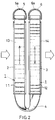
- Fig. 2 is a cross section taken along the line 2 - 2 in Fig. 1;
- Fig. 3 is a front elevation of the heat exchanger;
- Fig. 4 is a plan view of the heat exchanger;
- Fig. 5 is a bottom view of the heat exchanger;
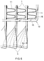
- Fig. 6 is an enlarged and partial front elevation of the heat exchanger's portion where tubes are bent and twisted;
- Fig. 7 is an enlarged and partial perspective view of a reinforcing strip incorporated in the heat exchanger;
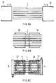
- Figs. 8A, 8B and 8C show the successive steps carried out in this order to manufacture the heat exchanger;
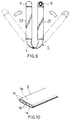
- Fig. 9 shows the further step of bending the tubes;
- Fig. 10 is a perspective view of the flat tube, shown in part;
- Fig. 11 is a cross section of a modified header incorporated in the heat exchanger;
- Fig. 12 is a cross section of a modification in which baffles are inserted in the header;
- Fig. 13 is an enlarged and partial perspective view of a modified reinforcing strip;
- Fig. 14 is a plan view of a modified heat exchanger;
- Fig. 15 is a graph showing a relationship observed between the heat rejection and the pressure of a medium at an outlet of the heat exchanger;
- Fig. 16 is another graph showing a relationship observed between the pressure drop of the heat exchanging medium and the flow rate thereof;
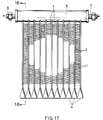
- Figs. 17 to 21 show another heat exchanger provided in a second embodiment and as an evaporator, in which:
- Fig. 17 is a front elevation of the heat exchanger;
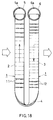
- Fig. 18 is a cross section taken along the line 18 - 18 in Fig. 17;
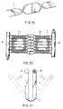
- Fig. 19 is a perspective view of a tube incorporated in the heat exchanger, and shown in its twisted state;
- Fig. 20 is a front elevation of the heat exchanger, shown in its state before being bent; and
- Fig. 21 is a plan view of the heat exchanger, shown in its further state after bent;
Figs. 22 and 23 illustrate still another heat exchanger provided in a third embodiment and as a condenser, in which: - Fig. 22 is a perspective view of the heat exchanger, shown in its entirety; and
- Fig. 23 is a left side elevation of the heat exchanger.
- Now, some embodiments of the present invention will be described referring to the drawings.
- A heat exchanger which Figs. 1 to 16 illustrate is an evaporator provided in the first embodiment for use in a car air conditioner.
- Each of flat
heat exchanging tubes 1 shown in Fig. 1 is of an elliptic shape in cross section and has an upper and lowerflat walls 1a. Those flat walls la are connected one to another by a few connectingwalls 1b so thatseveral unit paths 1c are defined in and longitudinally of the tube, as seen in Fig. 10. - The
tubes 1 are aluminum extruded pieces of the so-called harmonica structure in this embodiment. However, they may be flat seam-welded tubes having inserted therein internal corrugated fins, or of any other conventional structure in the present invention. - Each of the
flat tubes 1 shown in Figs. 1 and 2 hasstraight sections middle portion 4 integral with and intervening between them. Thismiddle portion 4 is bent and twisted to have a predetermined helical angle relative to the straight sections. In this embodiment, the bent and twistedmiddle portion 4 is generally U-shaped such that thestraight sections - The
tube 1 may not be bent into a U-shape but into a V-shape or the like such that thestraight sections twisted portion 4 may not necessarily be positioned right in the middle of each tube. - An outer edge of the bent and
twisted portion 4 lies almost in parallel with thestraight sections - The
bent portion 4 preferably of a smooth and arcuate contour is usually designed as short as the torsional strength allows. Any specific configuration and radius of curvature may be employed so long as the internal flow path of tube substantially remains non-collapsed and has an unconstricted cross-sectional area. - The generally U-shaped
flat tubes 1 having at their bottoms the bent andtwisted portions 4 are arranged such that their verticalstraight sections hollow headers - As seen in Fig. 6, the
bent portions 4 of theadjacent tubes 1 overlap and fit on each other so as to support one another and improve their strength. Those bent portions may be brazed or otherwise secured one to another to further raise the strength. - Fins such as aluminum corrugated
fins 11 are disposed between the adjacentstraight sections 2 located windward and also outside the outermoststraight sections 2.Similar fins 12 are disposed between the adjacentstraight sections 3 located leeward and also outside the outermoststraight sections 3. Those fins are brazed to thestraight sections windward fins 11 is greater than that of theleeward ones 12. - A front reinforcing
strip 13 is secured to and surrounds the group of windwardstraight sections 2, while arear reinforcing strip 14 being likewise secured to and surrounding the group of leewardstraight sections 3. Each reinforcing strip is made by bending an elongate plate, and has amiddle section 15 andend sections 16 bent upward and extending therefrom so that it assumes a U-shape in front elevation. - As shown in Fig. 7,
apertures 15a are formed through themiddle section 15 at a pitch corresponding to theflat tubes 1. A boundary between the bent portion and thestraight section corresponding aperture 15a in which thetube 1 is inserted. - Each of the
end sections 16 is in contact with and brazed to thefin outermost tube 1. It is preferable that, in order to facilitate the brazing process, the reinforcing strips are made of a sheet which is composed of a core having either or both surfaces clad with a brazing agent layer. - The reinforcing strips 13 and 14, which contribute to an improved strength of the core of this heat exchanger, circumscribe the bending and twisting action within narrow bounds. The tubes' straight sections are thus protected from any torsion or bending.
- The
middle section 15 of each reinforcingstrip drainage holes 15b formed therethrough and/ordrainage trough portions 15c, as shown in Fig. 13, which will prevent stagnation of the condensed water. - The
headers - Such a specific cross-sectional shape of the headers is advantageous in that ends of each
tube 1 need not be inserted so deep as to reach an axis of the header, contrary to the case of using headers of a circular cross section. Thus, an effective length of eachtube 1 is made greater to thereby increase the effective area of the core. - Alternatively, the
headers - Fig. 12 shows baffles 10 each secured to a part of cylindrical wall of each
header tubes 1 are secured. Eachbaffle 10 is located between the adjacent tubes and comprises a base 10a and aleg 10b. Thisleg 10b protrudes inwardly towards the tubes' ends so that the heat exchanging medium is smoothly and evenly distributed into the tubes. The base 10a is fixed to an outer peripheral surface of theheader - In use, the heat exchanging medium will flow into a leeward one of the
headers 6 through aninlet pipe 7 liquid-tightly connected thereto. Tributaries of the medium will flow through therespective tubes 1, each making a U-turn to enter thewindward header 5, as indicated at the arrows in Fig. 1. The tributaries through thetubes 1 join one another in the windward header and leave it through anoutlet pipe 8, after heat exchange has been effected between the medium and air streams penetrating this heat exchanger from front to rear as shown by the white arrows. - The
inlet pipe 7 andoutlet pipe 8 may be attached to the headers at their ends located side by side, as shown in Fig. 14, so that the heat exchanging medium can flow into and out of the same side end of the heat exchanger. Further, aninternal pipe 60 havingsmall holes 60a corresponding to the tubes may be secured in and coaxially of the inlet side (viz. leeward)header 6. Such an internal pipe connected to theinlet pipe 7 will ensure an even distribution of the heat exchanging medium into the tubes. - The described heat exchanger may be manufactured, for example in the following manner.
- Flat and
straight aluminum tubes 1 which are prepared by extrusion will be arranged in parallel and at regular intervals in a direction of their thickness, in a manner shown in Fig. 8A. Next, the tube ends are caused to penetrate the reinforcingstrips headers corrugated fins adjacent tubes 1 and also between the outermost tube and theend section 16 of the reinforcing strip as shown in Fig. 8C. Any brazeable accessories may be attached to the thus prepared assembly which will then be 'one-shot' brazed so that all the parts become integral with each other. - The brazed assembly will further be subjected to the bending process in which each
tube 1 is bent at its middle portion in the direction of its thickness, so that its straight sections lie in parallel with each other, as shown in Fig. 9. It may be preferable to use a proper tool to give all the middle portions a slight pretwist which will allow them to readily twist in the same direction. - Thus in manufacture of the heat exchanger, the
tubes 1 can easily be twisted in the direction of their width, at any predeterminedmiddle portions 4 and at a predetermined helical angle relative to their straight sections, whether pretwisted to any extent or not. - It is also easy in the present invention to give a small radius of curvature to the bent and twisted
middle portions 4 of thetubes 1 so that each of them is bent to assume a U-shape. - Although the
straight sections windward fins 11 is designed larger than that ofleeward ones 12 so that a satisfactory performance is afforded as to the heat exchange. - A higher productivity is realized herein, because the flat
heat exchanging tubes 1 are bent all at once after the necessary parts are assembled. - In the described embodiment, the coolant flowing into the
leeward header 6 is distributed to all the tubes forming tributaries connected thereto. Those tributaries join one another in harmony in thewindward header 5 to construct the so-called 'one pass' system. Partitions may be secured in theheaders - It is however noted that the 'one pass' system is more desirable in this type of evaporators as to their heat exchanging performance, as will be apparent from the following.
- Samples of heat exchangers were prepared, which each comprised a core 235 mm high and 258 mm wide so that an effective size of the core was 178 mmH x 259 mmW. The tube pitch was set at 11.7 mm, with the number of tubes being 21, each fin being 22 mm wide and 10 mm high, and fin pitch being 1.1 mm. One of the sample heat exchangers was of the 'two pass' type, having the partitions dividing the tubes into a first group of 10 tubes and a second group of 11 tubes. A performance test was conducted using HFC134a as the heat exchanging medium and under the operating conditions that: the temperature of said medium at an inlet of expansion valve was 53.5 °C; dry-bulb temperature of affluent air was 27 °C; wet-bulb temperature of effluent air was 19.5 °C; and 'SH' (super-heating) was 5 °C. Fig. 15 shows a relationship observed between the heat rejection (kcal/h) and the medium pressure at outlet (kg/cm²). Fig. 16 shows another relationship observed between the pressure loss of the medium (kg/cm²) and the flow rate thereof (kg/h).
- As seen in Figs. 15 and 16, the evaporator of 'one pass' type was superior to that of 'two pass' type not only in the exchanged heat but also in the pressure loss.
- Fig. 17 to 21 illustrate the second embodiment of the present invention also applied to an evaporator for use in car air conditioners.
- This evaporator is of a structure almost similar to that provided in the first embodiment, but different therefrom in: the cross-sectional shape of headers; the reinforcing strips dispensed with; and the configuration of the tubes' bent and twisted portions. Such differences will be briefed below.
- A bottom of each bent and
twisted portion 4 of thetubes 1 lies at 90°, viz. perpendicular, to thestraight sections bent portions 4 do not overlap one another, as seen in Fig. 17. - The
headers - The heat exchanger in the second embodiment does not comprise any reinforcing strips.
- The
tubes 1 are preliminarily twisted at first at their middle portions as shown in Fig. 19, before assembled into a state shown in Fig. 20 and subsequently bent in a manner shown in Fig. 21 to provide a finished heat exchanger. It may be possible to twist and simultaneously bent those tubes, also in the second embodiment. - Other features are the same as those employed in the first embodiment, and therefore the same reference numerals are allotted thereto to abbreviate description.
- A condenser provided in the third embodiment is for use in car air conditioners.
- This condenser differs from the evaporators provided in the first embodiment only in that: the
headers straight sections tube 1 are disposed horizontally; each header is of a round cross section; and the partitioning members inserted in headers. Theround headers partitioning members 20 shown in Fig. 22 divides the interior ofheader - Other features are the same as those employed in the first embodiment, and therefore the same reference numerals are allotted thereto to abbreviate description.
- In summary, each flat tube has its middle portion that is located intermediate its straight sections, bent in the direction of the tube's width and twisted at a predetermined angle relative to the straight sections.
- Consequently, it is possible to arrange a plurality of flat and straight tubes in parallel and at regular intervals and to connect the headers to ends of the tubes, before bending them at their middle portions all at once and simultaneously twisting them at the predetermined angle. Thus, the bending-and-twisting operation encounters no technical difficulty and can now be done easily to facilitate manufacture of such 'bent tube' type heat exchangers.
- There is no fear of collapsing the bent and twisted portions to result in a reduced cross-sectional area and an increased pressure loss thereof.
- In a case wherein the heat exchanger comprises the aforementioned reinforcing strips each composed of the middle section and the end sections continuing therefrom and formed perpendicular thereto, the straight sections are protected from deformation during the bending-and-twisting operation. This is because a stress imparted to the tubes which are being bent is restricted to their middle portions located between the middle sections of said strips, even if each tube is forced to have a considerably small radius of curvature. The reinforcing strips thus contribute not only to an easier manufacture but also to an improved overall strength of the heat exchanger.
- The overlapping of the adjacent bent portions will further improve their strength as a whole.
Claims (16)
- A heat exchanger comprising:
a plurality of flat tubes arranged at regular intervals and in parallel with and spaced apart from each other a predetermined distance in the direction of thickness of the tubes;
a pair of hollow headers disposed at one ends and other ends of the tubes, which are connected thereto in fluid communication therewith;
each tube having an intermediate bent portion and straight sections separated one from another by the bent portion;
the bent portion being a portion of each tube twisted at a predetermined helical angle relative to each of the straight sections; and
fins each interposed between the adjacent straight sections. - A heat exchanger comprising:
a plurality of flat tubes arranged at regular intervals and in parallel with and spaced apart from each other a predetermined distance in the direction of thickness of the tubes;
a pair of hollow headers disposed at one ends and other ends of the tubes, which are connected thereto in fluid communication therewith;
each tube having an intermediate bent portion and straight sections separated one from another by the bent portion;
the bent portion being a portion of each tube twisted at a predetermined helical angle relative to each of the straight sections;
fins each interposed between the adjacent straight sections;
additional fins disposed outside the outermost tubes; and
reinforcing strips each composed of a middle section and end sections continuing therefrom,
wherein the middle section of each reinforcing strip has formed therethrough apertures each fitting on a boundary present between the straight section and the twisted bent portion of each tube, and each end section of the reinforcing strip extending along and fixedly adjoined to the outer surface of the corresponding additional fin. - A heat exchanger as defined in claim 1 or 2, wherein the twisted and bent portions located adjacent to each other contact and overlap one another to reinforce said portions as a whole.
- A heat exchanger as defined in claim 3, wherein the twisted and bent portions are brazed to be integral with each other.
- A heat exchanger as defined in claim 1 or 2, wherein the headers are disposed horizontally, and the straight sections of each tube stand upright, so as to render the heat exchanger adapted to operate as an evaporator.
- A heat exchanger as defined in claim 1 or 2, wherein each of the headers has an interior not divided into compartments, so that a heat exchanging medium flowing into one header advances as tributaries flowing in harmony through all the tubes at once and into the other header, whereby the heat exchanger is formed as an evaporator of the one pass type.
- A heat exchanger as defined in claim 1 or 2, wherein the headers stand upright and the straight sections of each tube are disposed horizontally, so as to render the heat exchanger adapted to operate as a condenser.
- A heat exchanger as defined in claim 1 or 2, wherein one of the straight sections of each tube is disposed windward, with the other section disposed leeward, so that a heat exchanging medium flowing into leeward straight section advances into the windward section.
- A heat exchanger as defined in claim 1 or 2, wherein each header is of a cross-sectional shape having a flat bottom continuing to a dome, so that the flat bottom receives the tubes inserted therein.
- A heat exchanger as defined in claim 1 or 2, wherein each header is of a cross-sectional shape composed of an inner and outer semi-peripheries, and a radius of curvature of the inner semi-periphery receiving the tubes is greater than that of the outer semi-periphery.
- A heat exchanger as defined in claim 1 or 2, wherein each header is a cylinder of a brazing sheet composed of a core having at least one side clad with a brazing agent layer, and the brazing sheet has abutment edges integrally brazed one to another.
- A heat exchanger as defined in claim 1 or 2, wherein each tube is bent at its middle portion so as to be U-shaped, and the straight sections of each tube stand in parallel with each other.
- A heat exchanger as defined in claim 2, wherein each middle section of the reinforcing strips has drainage means selected from a group consisting of drainage holes and drainage troughs, the holes being formed through the middle section and with the troughs formed therein.
- A heat exchanger as defined in claim 1 or 2, wherein each tube has an interior which is divided into windward and leeward unit paths located side by side and longitudinally of the tube, so that a heat exchanging medium flowing through the leeward unit path in one of the straight sections located leeward is guided by the intermediate bent portion into the windward unit path in the other straight section located windward.
- A heat exchanger as defined in claim 1 or 2, wherein the header connected to an inlet pipe of the heat exchanger has an internal pipe secured in and coaxially with the header, the internal pipe being connected to the inlet pipe, and wherein the inlet pipe and an outlet pipe are attached to the headers at ends thereof located side by side.
- A heat exchanger as defined in claim 15, wherein the internal pipe has small holes corresponding to the tubes so that the heat exchanging medium is distributed evenly into the tubes.
Applications Claiming Priority (2)
| Application Number | Priority Date | Filing Date | Title |
|---|---|---|---|
| JP29343993A JP3305460B2 (en) | 1993-11-24 | 1993-11-24 | Heat exchanger |
| JP293439/93 | 1993-11-24 |
Publications (3)
| Publication Number | Publication Date |
|---|---|
| EP0654645A2 true EP0654645A2 (en) | 1995-05-24 |
| EP0654645A3 EP0654645A3 (en) | 1995-11-02 |
| EP0654645B1 EP0654645B1 (en) | 1999-01-07 |
Family
ID=17794782
Family Applications (1)
| Application Number | Title | Priority Date | Filing Date |
|---|---|---|---|
| EP94308661A Expired - Lifetime EP0654645B1 (en) | 1993-11-24 | 1994-11-23 | Heat exchanger |
Country Status (9)
| Country | Link |
|---|---|
| US (1) | US5531268A (en) |
| EP (1) | EP0654645B1 (en) |
| JP (1) | JP3305460B2 (en) |
| KR (1) | KR100335872B1 (en) |
| CN (1) | CN1074526C (en) |
| AT (1) | ATE175492T1 (en) |
| AU (1) | AU678620B2 (en) |
| DE (1) | DE69415779T2 (en) |
| ES (1) | ES2127358T3 (en) |
Cited By (25)
| Publication number | Priority date | Publication date | Assignee | Title |
|---|---|---|---|---|
| DE19830863A1 (en) * | 1998-07-10 | 2000-01-13 | Behr Gmbh & Co | Flat tube with transverse offset reversing bend section and thus built-up heat exchanger |
| FR2793013A1 (en) * | 1999-04-28 | 2000-11-03 | Valeo Thermique Moteur Sa | Heat exchanger assembly for an automobile, utilises a cross flow configuration between the fluid supply and sump assemblies via tubular plate type heat exchange fins |
| AU740183B2 (en) * | 1999-05-31 | 2001-11-01 | Mitsubishi Heavy Industries, Ltd. | Heat exchanger |
| EP1231448A2 (en) * | 2001-02-07 | 2002-08-14 | Modine Manufacturing Company | Heat exchanger |
| WO2004005826A1 (en) * | 2002-07-03 | 2004-01-15 | Behr Gmbh & Co. | Heat exchanger |
| DE10241635A1 (en) * | 2001-10-02 | 2004-02-05 | Behr Gmbh & Co. | Flat pipe heat exchanger for a heating or air-conditioning system of a motor vehicle comprises a collecting tube, and flat pipe elements connected to the collecting tube and having a torsion region |
| EP1397623A1 (en) * | 2001-06-18 | 2004-03-17 | Showa Dendo K.K. | Evaporator, manufacturing method of the same, header for evaporator and refrigeration system |
| KR20040038328A (en) * | 2002-10-31 | 2004-05-08 | 엘지전자 주식회사 | Coupling device for regenerator |
| EP1452814A1 (en) * | 2001-11-08 | 2004-09-01 | Zexel Valeo Climate Control Corporation | Heat exchanger and tube for heat exchanger |
| GB2400648A (en) * | 2003-03-19 | 2004-10-20 | Calsonic Kansei Uk Ltd | An automotive heat exchanger |
| WO2004074756A3 (en) * | 2003-02-18 | 2004-10-21 | Behr Gmbh & Co Kg | Flat pipe comprising a return bend section and a heat exchanger constructed therewith |
| FR2907887A1 (en) * | 2006-10-25 | 2008-05-02 | Valeo Systemes Thermiques | Heat exchanger for motor vehicle, has fin portions respectively fixed in contact with fluid circulation tubes, where tubes are covered with filler metal plating at level of contact and fin portions are free from plating near rupture |
| WO2008058734A1 (en) * | 2006-11-15 | 2008-05-22 | Behr Gmbh & Co. Kg | Heat exchanger |
| WO2008064251A2 (en) * | 2006-11-22 | 2008-05-29 | Johnson Controls Technology Company | Space-saving multichannel heat exchanger |
| WO2009018159A2 (en) * | 2007-07-27 | 2009-02-05 | Johnson Controls Technology Company | Multi-slab multichannel heat exchanger |
| US7942020B2 (en) | 2007-07-27 | 2011-05-17 | Johnson Controls Technology Company | Multi-slab multichannel heat exchanger |
| CN101850391B (en) * | 2009-03-31 | 2012-07-04 | 三花丹佛斯(杭州)微通道换热器有限公司 | Flat pipe processing method, flat pipe, heat exchanger processing method and heat exchanger |
| DE202013101092U1 (en) | 2012-03-14 | 2013-07-02 | Valmex S.P.A. | Heat exchanger, which is particularly suitable for use as an evaporator |
| EP2865982A4 (en) * | 2012-04-26 | 2016-03-30 | Mitsubishi Electric Corp | Heat exchanger, and refrigerating cycle device equipped with heat exchanger |
| WO2016081306A1 (en) * | 2014-11-17 | 2016-05-26 | Carrier Corporation | Multi-pass and multi-slab folded microchannel heat exchanger |
| KR20160116888A (en) * | 2015-03-31 | 2016-10-10 | 한국교통대학교산학협력단 | Heat exchanger with return cap and method for exchanging using the heat exchanger |
| EP2378232A3 (en) * | 2010-04-13 | 2017-04-19 | Sanhua (Hangzhou) Micro Channel Heat Exchanger Co., Ltd. | Bent micro-channel heat exchanger |
| EP2671032B1 (en) | 2011-02-04 | 2018-05-09 | MAHLE Behr GmbH & Co. KG | Heat exchanger |
| RU2693946C2 (en) * | 2014-11-26 | 2019-07-08 | Кэрриер Корпорейшн | Micro-channel heat exchanger resistant to frost formation |
| WO2020081389A1 (en) * | 2018-10-18 | 2020-04-23 | Carrier Corporation | Microchannel heat exchanger tube supported bracket |
Families Citing this family (82)
| Publication number | Priority date | Publication date | Assignee | Title |
|---|---|---|---|---|
| KR100532187B1 (en) * | 1998-11-28 | 2006-02-08 | 한라공조주식회사 | Evaporator |
| DE19859756B4 (en) * | 1998-12-23 | 2007-04-19 | Behr Gmbh & Co. Kg | heat exchangers |
| JP4632273B2 (en) * | 2000-04-18 | 2011-02-16 | ティーエス ヒートロニクス 株式会社 | Heat sink and manufacturing method thereof |
| TW475052B (en) * | 2001-07-18 | 2002-02-01 | Chiun-Yau Jeng | Heat-dissipating blade device |
| US6830100B2 (en) * | 2001-11-02 | 2004-12-14 | Thermalex, Inc. | Extruded manifold |
| DE10158436A1 (en) * | 2001-11-29 | 2003-06-12 | Behr Gmbh & Co | heat exchangers |
| US20030102113A1 (en) | 2001-11-30 | 2003-06-05 | Stephen Memory | Heat exchanger for providing supercritical cooling of a working fluid in a transcritical cooling cycle |
| US20030106677A1 (en) * | 2001-12-12 | 2003-06-12 | Stephen Memory | Split fin for a heat exchanger |
| JP4121085B2 (en) * | 2001-12-21 | 2008-07-16 | ベール ゲーエムベーハー ウント コー カーゲー | Especially heat exchanger for automobile |
| EP1527310A2 (en) * | 2002-07-26 | 2005-05-04 | Behr GmbH & Co. | Device for heat exchange |
| DE10237648A1 (en) * | 2002-08-13 | 2004-02-26 | Behr Gmbh & Co. | Heat transmitter of parallel flat tubes fits open tube ends into contour-matched manifold for fluid transfer steadying tubes by outside and center stays. |
| FR2847973B1 (en) * | 2002-11-29 | 2006-01-27 | Valeo Climatisation | THERMAL INERTIAL HEAT EXCHANGER FOR A HEAT PUMP CIRCUIT, IN PARTICULAR A MOTOR VEHICLE. |
| DE102004018317A1 (en) * | 2004-04-13 | 2005-11-03 | Behr Gmbh & Co. Kg | Heat exchanger for motor vehicles |
| US7281387B2 (en) * | 2004-04-29 | 2007-10-16 | Carrier Commercial Refrigeration Inc. | Foul-resistant condenser using microchannel tubing |
| JP2005321151A (en) * | 2004-05-10 | 2005-11-17 | Sanden Corp | Heat exchanger |
| US7104314B2 (en) * | 2004-06-29 | 2006-09-12 | Modine Manufacturing Company | Multi-pass heat exchanger |
| US8091620B2 (en) * | 2005-02-02 | 2012-01-10 | Carrier Corporation | Multi-channel flat-tube heat exchanger |
| US20070000652A1 (en) * | 2005-06-30 | 2007-01-04 | Ayres Steven M | Heat exchanger with dimpled tube surfaces |
| US20070114005A1 (en) * | 2005-11-18 | 2007-05-24 | Matthias Bronold | Heat exchanger assembly for fuel cell and method of cooling outlet stream of fuel cell using the same |
| JP2008045862A (en) * | 2006-08-21 | 2008-02-28 | Daikin Ind Ltd | Heat exchanger, and method of manufacturing heat exchanger |
| JP2008122058A (en) * | 2006-10-17 | 2008-05-29 | Alps Electric Co Ltd | Radiator and cooling system |
| US7921904B2 (en) * | 2007-01-23 | 2011-04-12 | Modine Manufacturing Company | Heat exchanger and method |
| JP2009216315A (en) * | 2008-03-11 | 2009-09-24 | Showa Denko Kk | Heat exchanger |
| US20110094257A1 (en) * | 2008-03-20 | 2011-04-28 | Carrier Corporation | Micro-channel heat exchanger suitable for bending |
| JP5444782B2 (en) * | 2008-09-12 | 2014-03-19 | 株式会社デンソー | Cold storage heat exchanger |
| CN101806550B (en) * | 2010-03-24 | 2014-02-19 | 三花控股集团有限公司 | Microchannel heat exchanger |
| CN101890446B (en) * | 2010-07-28 | 2012-07-18 | 三花丹佛斯(杭州)微通道换热器有限公司 | Heat exchanger bending method and heat exchanger bending tool |
| DE102010032899A1 (en) * | 2010-07-30 | 2012-02-02 | Valeo Klimasysteme Gmbh | Cooling device for a vehicle battery and vehicle battery assembly with such a cooling device |
| CN101936672B (en) * | 2010-09-15 | 2012-09-19 | 三花控股集团有限公司 | Heat exchanger with improved surface airflow field distribution uniformity |
| CN102330719A (en) * | 2011-07-29 | 2012-01-25 | 烟台富耐克散热器有限公司 | Tube-strip type oil radiator |
| CN103890532B (en) | 2011-10-19 | 2020-06-19 | 开利公司 | Flat tube fin heat exchanger and method of manufacture |
| US9689594B2 (en) | 2012-07-09 | 2017-06-27 | Modine Manufacturing Company | Evaporator, and method of conditioning air |
| DE102012222664A1 (en) * | 2012-08-09 | 2014-03-06 | Behr Gmbh & Co. Kg | capacitor |
| USD736904S1 (en) * | 2013-02-05 | 2015-08-18 | Modine Manufacturing Company | Heat exchanger |
| US9341418B2 (en) * | 2013-03-01 | 2016-05-17 | International Business Machines Corporation | Thermal transfer structure with in-plane tube lengths and out-of-plane tube bend(s) |
| CN103196259B (en) * | 2013-03-20 | 2016-04-06 | 杭州三花微通道换热器有限公司 | Bendable heat exchanger |
| US9891007B2 (en) | 2013-03-21 | 2018-02-13 | Sanhua (Hangzhou) Micro Channel Heat Exchanger Co., Ltd. | Bent heat exchanger and method for manufacturing the same |
| US9851160B2 (en) * | 2013-05-03 | 2017-12-26 | Trane International Inc. | Mounting assembly for heat exchanger coil |
| CN104344745A (en) * | 2013-08-02 | 2015-02-11 | 杭州三花微通道换热器有限公司 | Heat exchanger and manufacturing method thereof |
| WO2015037235A1 (en) * | 2013-09-11 | 2015-03-19 | ダイキン工業株式会社 | Heat exchanger, air conditioner, and heat exchanger manufacturing method |
| WO2015040746A1 (en) * | 2013-09-20 | 2015-03-26 | 三菱電機株式会社 | Heat exchanger, air conditioner device using said heat exchanger, and method for producing said heat exchanger |
| KR102174510B1 (en) * | 2013-11-05 | 2020-11-04 | 엘지전자 주식회사 | Refrigeration cycle of refrigerator |
| CN105202816B (en) * | 2014-06-16 | 2017-08-22 | 杭州三花研究院有限公司 | Bent heat exchanger |
| US10247482B2 (en) * | 2013-12-13 | 2019-04-02 | Hangzhou Sanhua Research Institute Co., Ltd. | Bent heat exchanger and method for bending the heat exchanger |
| CN104713387B (en) * | 2013-12-13 | 2017-01-11 | 杭州三花研究院有限公司 | Bending heat exchanger and bending method of heat exchanger |
| CN104807360B (en) * | 2014-01-26 | 2018-10-19 | 杭州三花研究院有限公司 | Fin, the micro-channel heat exchanger with the fin and its application |
| CN104880116A (en) | 2014-02-27 | 2015-09-02 | 杭州三花研究院有限公司 | Header and heat exchanger with same |
| JP2017516660A (en) | 2014-03-28 | 2017-06-22 | モーディーン・マニュファクチャリング・カンパニーModine Manufacturing Company | Heat exchanger and heat exchanger manufacturing method |
| DE102014206612A1 (en) | 2014-04-04 | 2015-10-29 | Mahle International Gmbh | heat exchangers |
| KR101600878B1 (en) * | 2014-06-19 | 2016-03-09 | 갑을오토텍 주식회사 | Heat Exchanger and Heating, Ventilation, Air Conditioning System for Vehicle Having the Same |
| EP3194872B1 (en) * | 2014-09-05 | 2019-10-30 | Carrier Corporation | Multiport extruded heat exchanger |
| JP2016064057A (en) * | 2014-09-25 | 2016-04-28 | シャープ株式会社 | Dryer |
| US10113817B2 (en) * | 2014-09-30 | 2018-10-30 | Valeo Climate Control Corp. | Heater core |
| CN106403694A (en) * | 2015-07-28 | 2017-02-15 | 苏州三星电子有限公司 | Dual-row collecting pipe, heat exchanger using collecting pipe and manufacturing method thereof |
| CN106642826B (en) * | 2015-10-28 | 2019-04-19 | 丹佛斯微通道换热器(嘉兴)有限公司 | Heat exchanger |
| USD787033S1 (en) * | 2015-12-24 | 2017-05-16 | Danfoss Micro Channel Heat Exchanger (Jiaxing) Co., Ltd. | Heat exchanger |
| CN105651081B (en) * | 2015-12-30 | 2018-07-13 | 杭州三花微通道换热器有限公司 | Double bendable heat exchanger and its manufacturing method |
| CN107449182A (en) * | 2016-05-30 | 2017-12-08 | 杭州三花家电热管理系统有限公司 | Heat exchanger and household electrical appliance |
| CN107560484B (en) * | 2016-06-30 | 2020-05-19 | 浙江盾安热工科技有限公司 | Connecting piece and microchannel heat exchanger |
| CN106500525A (en) * | 2016-12-06 | 2017-03-15 | 广东申菱环境系统股份有限公司 | A kind of cast aluminium composition metal heat-exchanger rig and preparation method thereof |
| CN106524792A (en) * | 2016-12-30 | 2017-03-22 | 广东申菱环境系统股份有限公司 | Modularized concatenation heat exchanger and producing method thereof |
| DE102017203258A1 (en) | 2017-02-28 | 2018-08-30 | Mahle International Gmbh | heater |
| WO2018231194A1 (en) * | 2017-06-12 | 2018-12-20 | General Electric Company | Counter-flow heat exchanger |
| CN107328280A (en) * | 2017-07-06 | 2017-11-07 | 贺迈新能源科技(上海)有限公司 | A kind of hot pond of multiple-unit transverse tube |
| CN107504836A (en) * | 2017-09-20 | 2017-12-22 | 杭州三花家电热管理系统有限公司 | Heat exchanger, heat-exchange system and indoor heating system |
| AU2018267568A1 (en) * | 2017-11-22 | 2019-09-12 | Transportation Ip Holdings, Llc | Thermal management system and method |
| KR102463489B1 (en) * | 2017-12-18 | 2022-11-08 | 한온시스템 주식회사 | Heat exchanger |
| FR3075347B1 (en) * | 2017-12-19 | 2020-05-15 | Valeo Systemes Thermiques | DEVICE FOR DISTRIBUTING A REFRIGERANT FLUID TO BE HOUSED IN A COLLECTOR BOX OF A HEAT EXCHANGER |
| CN110153319B (en) * | 2019-06-05 | 2021-02-26 | 珠海格力智能装备有限公司 | Control method and device for bending of predetermined equipment, storage medium and processor |
| DE202019103964U1 (en) * | 2019-07-18 | 2020-10-21 | Akg Verwaltungsgesellschaft Mbh | Heat exchanger |
| EP3809087B1 (en) * | 2019-10-18 | 2022-04-27 | Hamilton Sundstrand Corporation | Heat exchanger |
| US11448132B2 (en) | 2020-01-03 | 2022-09-20 | Raytheon Technologies Corporation | Aircraft bypass duct heat exchanger |
| EP4239273A1 (en) * | 2020-01-19 | 2023-09-06 | Raytheon Technologies Corporation | Aircraft heat exchanger |
| US11525637B2 (en) | 2020-01-19 | 2022-12-13 | Raytheon Technologies Corporation | Aircraft heat exchanger finned plate manufacture |
| US11674758B2 (en) | 2020-01-19 | 2023-06-13 | Raytheon Technologies Corporation | Aircraft heat exchangers and plates |
| US11585273B2 (en) | 2020-01-20 | 2023-02-21 | Raytheon Technologies Corporation | Aircraft heat exchangers |
| US11585605B2 (en) | 2020-02-07 | 2023-02-21 | Raytheon Technologies Corporation | Aircraft heat exchanger panel attachment |
| US11890663B2 (en) | 2020-09-23 | 2024-02-06 | Mahle International Gmbh | Device and method for opening folded heat exchanger cores |
| CN115451748A (en) * | 2021-06-09 | 2022-12-09 | 浙江盾安热工科技有限公司 | Flat pipe and heat exchanger |
| CN113432454B (en) * | 2021-07-14 | 2022-12-06 | 哈尔滨锅炉厂有限责任公司 | Non-circular cross-section double-tube-pass spiral heat exchanger tube bundle structure |
| KR20240038759A (en) * | 2021-09-13 | 2024-03-25 | 제지앙 둔안 아트피셜 인바이런먼트 컴퍼니 리미티드 | Heat exchangers and microchannel heat exchangers |
| CN217383881U (en) * | 2022-03-16 | 2022-09-06 | 浙江盾安热工科技有限公司 | Heat exchanger |
Citations (4)
| Publication number | Priority date | Publication date | Assignee | Title |
|---|---|---|---|---|
| DE1900358A1 (en) * | 1969-01-04 | 1970-07-30 | Schoell Dr Ing Guenter | Space heater made of one or more coils |
| US3750709A (en) * | 1970-05-18 | 1973-08-07 | Noranda Metal Ind | Heat-exchange tubing and method of making it |
| US4625378A (en) * | 1983-05-09 | 1986-12-02 | Matsushita Refrigeration Company | Method of manufacturing fin-tube heat exchangers |
| US5036909A (en) * | 1989-06-22 | 1991-08-06 | General Motors Corporation | Multiple serpentine tube heat exchanger |
Family Cites Families (13)
| Publication number | Priority date | Publication date | Assignee | Title |
|---|---|---|---|---|
| DE8584C (en) * | ||||
| US2894731A (en) * | 1955-07-18 | 1959-07-14 | Gen Motors Corp | Refrigerating apparatus |
| NL243820A (en) * | 1959-01-28 | |||
| US3273227A (en) * | 1963-06-12 | 1966-09-20 | Olin Mathieson | Fabrication of heat exchange devices |
| US3416600A (en) * | 1967-01-23 | 1968-12-17 | Whirlpool Co | Heat exchanger having twisted multiple passage tubes |
| EP0138435A3 (en) * | 1983-10-19 | 1986-05-14 | General Motors Corporation | Tube and fin heat exchanger |
| GB2196730B (en) * | 1986-10-21 | 1991-06-26 | Austin Rover Group | A heat exchanger |
| JPS6447287A (en) * | 1987-08-13 | 1989-02-21 | Fuji Electric Co Ltd | Star-delta starting method for induction motor |
| JP3043051B2 (en) * | 1990-11-22 | 2000-05-22 | 昭和アルミニウム株式会社 | Heat exchange equipment |
| US5314013A (en) * | 1991-03-15 | 1994-05-24 | Sanden Corporation | Heat exchanger |
| US5190101A (en) * | 1991-12-16 | 1993-03-02 | Ford Motor Company | Heat exchanger manifold |
| US5205347A (en) * | 1992-03-31 | 1993-04-27 | Modine Manufacturing Co. | High efficiency evaporator |
| US5327959A (en) * | 1992-09-18 | 1994-07-12 | Modine Manufacturing Company | Header for an evaporator |
-
1993
- 1993-11-24 JP JP29343993A patent/JP3305460B2/en not_active Expired - Fee Related
-
1994
- 1994-11-22 US US08/345,712 patent/US5531268A/en not_active Expired - Fee Related
- 1994-11-23 ES ES94308661T patent/ES2127358T3/en not_active Expired - Lifetime
- 1994-11-23 AU AU78981/94A patent/AU678620B2/en not_active Ceased
- 1994-11-23 EP EP94308661A patent/EP0654645B1/en not_active Expired - Lifetime
- 1994-11-23 AT AT94308661T patent/ATE175492T1/en not_active IP Right Cessation
- 1994-11-23 DE DE69415779T patent/DE69415779T2/en not_active Expired - Fee Related
- 1994-11-24 KR KR1019940031051A patent/KR100335872B1/en not_active IP Right Cessation
- 1994-11-24 CN CN94120097A patent/CN1074526C/en not_active Expired - Fee Related
Patent Citations (4)
| Publication number | Priority date | Publication date | Assignee | Title |
|---|---|---|---|---|
| DE1900358A1 (en) * | 1969-01-04 | 1970-07-30 | Schoell Dr Ing Guenter | Space heater made of one or more coils |
| US3750709A (en) * | 1970-05-18 | 1973-08-07 | Noranda Metal Ind | Heat-exchange tubing and method of making it |
| US4625378A (en) * | 1983-05-09 | 1986-12-02 | Matsushita Refrigeration Company | Method of manufacturing fin-tube heat exchangers |
| US5036909A (en) * | 1989-06-22 | 1991-08-06 | General Motors Corporation | Multiple serpentine tube heat exchanger |
Cited By (37)
| Publication number | Priority date | Publication date | Assignee | Title |
|---|---|---|---|---|
| DE19830863A1 (en) * | 1998-07-10 | 2000-01-13 | Behr Gmbh & Co | Flat tube with transverse offset reversing bend section and thus built-up heat exchanger |
| WO2000003190A1 (en) * | 1998-07-10 | 2000-01-20 | Ford-Werke Aktiengesellschaft | Flat tube with transversally offset u-bend section and heat exchanger configured using same |
| FR2793013A1 (en) * | 1999-04-28 | 2000-11-03 | Valeo Thermique Moteur Sa | Heat exchanger assembly for an automobile, utilises a cross flow configuration between the fluid supply and sump assemblies via tubular plate type heat exchange fins |
| AU740183B2 (en) * | 1999-05-31 | 2001-11-01 | Mitsubishi Heavy Industries, Ltd. | Heat exchanger |
| EP1231448A2 (en) * | 2001-02-07 | 2002-08-14 | Modine Manufacturing Company | Heat exchanger |
| EP1231448A3 (en) * | 2001-02-07 | 2004-02-11 | Modine Manufacturing Company | Heat exchanger |
| US6964296B2 (en) | 2001-02-07 | 2005-11-15 | Modine Manufacturing Company | Heat exchanger |
| EP1397623A1 (en) * | 2001-06-18 | 2004-03-17 | Showa Dendo K.K. | Evaporator, manufacturing method of the same, header for evaporator and refrigeration system |
| EP1397623A4 (en) * | 2001-06-18 | 2006-06-14 | Showa Dendo K K | Evaporator, manufacturing method of the same, header for evaporator and refrigeration system |
| DE10241635A1 (en) * | 2001-10-02 | 2004-02-05 | Behr Gmbh & Co. | Flat pipe heat exchanger for a heating or air-conditioning system of a motor vehicle comprises a collecting tube, and flat pipe elements connected to the collecting tube and having a torsion region |
| EP1452814A1 (en) * | 2001-11-08 | 2004-09-01 | Zexel Valeo Climate Control Corporation | Heat exchanger and tube for heat exchanger |
| EP1452814A4 (en) * | 2001-11-08 | 2008-09-10 | Zexel Valeo Climate Contr Corp | Heat exchanger and tube for heat exchanger |
| WO2004005826A1 (en) * | 2002-07-03 | 2004-01-15 | Behr Gmbh & Co. | Heat exchanger |
| US7650934B2 (en) | 2002-07-03 | 2010-01-26 | Behr Gmbh & Co. | Heat exchanger |
| KR20040038328A (en) * | 2002-10-31 | 2004-05-08 | 엘지전자 주식회사 | Coupling device for regenerator |
| WO2004074756A3 (en) * | 2003-02-18 | 2004-10-21 | Behr Gmbh & Co Kg | Flat pipe comprising a return bend section and a heat exchanger constructed therewith |
| GB2400648A (en) * | 2003-03-19 | 2004-10-20 | Calsonic Kansei Uk Ltd | An automotive heat exchanger |
| EP1460364A3 (en) * | 2003-03-19 | 2011-09-21 | Calsonic Kansei UK Limited | Automotive heat exchangers |
| FR2907887A1 (en) * | 2006-10-25 | 2008-05-02 | Valeo Systemes Thermiques | Heat exchanger for motor vehicle, has fin portions respectively fixed in contact with fluid circulation tubes, where tubes are covered with filler metal plating at level of contact and fin portions are free from plating near rupture |
| WO2008058734A1 (en) * | 2006-11-15 | 2008-05-22 | Behr Gmbh & Co. Kg | Heat exchanger |
| WO2008064251A2 (en) * | 2006-11-22 | 2008-05-29 | Johnson Controls Technology Company | Space-saving multichannel heat exchanger |
| WO2008064251A3 (en) * | 2006-11-22 | 2008-10-09 | Johnson Controls Tech Co | Space-saving multichannel heat exchanger |
| US8561427B2 (en) | 2007-07-27 | 2013-10-22 | Johnson Controls Technology Company | Multi-slab multichannel heat exchanger |
| WO2009018159A2 (en) * | 2007-07-27 | 2009-02-05 | Johnson Controls Technology Company | Multi-slab multichannel heat exchanger |
| WO2009018159A3 (en) * | 2007-07-27 | 2009-04-23 | Johnson Controls Tech Co | Multi-slab multichannel heat exchanger |
| US7942020B2 (en) | 2007-07-27 | 2011-05-17 | Johnson Controls Technology Company | Multi-slab multichannel heat exchanger |
| CN101850391B (en) * | 2009-03-31 | 2012-07-04 | 三花丹佛斯(杭州)微通道换热器有限公司 | Flat pipe processing method, flat pipe, heat exchanger processing method and heat exchanger |
| EP2378232A3 (en) * | 2010-04-13 | 2017-04-19 | Sanhua (Hangzhou) Micro Channel Heat Exchanger Co., Ltd. | Bent micro-channel heat exchanger |
| EP2671032B1 (en) | 2011-02-04 | 2018-05-09 | MAHLE Behr GmbH & Co. KG | Heat exchanger |
| DE202013101092U1 (en) | 2012-03-14 | 2013-07-02 | Valmex S.P.A. | Heat exchanger, which is particularly suitable for use as an evaporator |
| EP2865982A4 (en) * | 2012-04-26 | 2016-03-30 | Mitsubishi Electric Corp | Heat exchanger, and refrigerating cycle device equipped with heat exchanger |
| US9689619B2 (en) | 2012-04-26 | 2017-06-27 | Mitsubishi Electric Corporation | Heat exchanger, refrigeration cycle apparatus including heat exchanger and air-conditioning apparatus |
| WO2016081306A1 (en) * | 2014-11-17 | 2016-05-26 | Carrier Corporation | Multi-pass and multi-slab folded microchannel heat exchanger |
| RU2722930C2 (en) * | 2014-11-17 | 2020-06-04 | Кэрриер Корпорейшн | Multi-stroke microchannel heat exchanger with multiple bent plates |
| RU2693946C2 (en) * | 2014-11-26 | 2019-07-08 | Кэрриер Корпорейшн | Micro-channel heat exchanger resistant to frost formation |
| KR20160116888A (en) * | 2015-03-31 | 2016-10-10 | 한국교통대학교산학협력단 | Heat exchanger with return cap and method for exchanging using the heat exchanger |
| WO2020081389A1 (en) * | 2018-10-18 | 2020-04-23 | Carrier Corporation | Microchannel heat exchanger tube supported bracket |
Also Published As
| Publication number | Publication date |
|---|---|
| JPH07146089A (en) | 1995-06-06 |
| ES2127358T3 (en) | 1999-04-16 |
| KR950014830A (en) | 1995-06-16 |
| JP3305460B2 (en) | 2002-07-22 |
| ATE175492T1 (en) | 1999-01-15 |
| DE69415779T2 (en) | 1999-05-27 |
| EP0654645B1 (en) | 1999-01-07 |
| DE69415779D1 (en) | 1999-02-18 |
| AU7898194A (en) | 1995-06-01 |
| CN1074526C (en) | 2001-11-07 |
| EP0654645A3 (en) | 1995-11-02 |
| CN1107221A (en) | 1995-08-23 |
| US5531268A (en) | 1996-07-02 |
| KR100335872B1 (en) | 2002-09-12 |
| AU678620B2 (en) | 1997-06-05 |
Similar Documents
| Publication | Publication Date | Title |
|---|---|---|
| EP0654645B1 (en) | Heat exchanger | |
| EP0414433A2 (en) | Duplex heat exchanger | |
| JP4050910B2 (en) | Heat exchanger | |
| USRE35655E (en) | Condenser for use in a car cooling system | |
| US5372188A (en) | Heat exchanger for a refrigerant system | |
| US4936379A (en) | Condenser for use in a car cooling system | |
| US5307870A (en) | Heat exchanger | |
| EP0559983B1 (en) | Evaporator or evaporator/condenser | |
| US4825941A (en) | Condenser for use in a car cooling system | |
| US5458190A (en) | Condenser | |
| US5246064A (en) | Condenser for use in a car cooling system | |
| US5190100A (en) | Condenser for use in a car cooling system | |
| JPH05312492A (en) | Heat exchanger | |
| JPH08145580A (en) | Heat exchanger | |
| JPH0345300B2 (en) | ||
| JPH0245945B2 (en) | ||
| US6854511B2 (en) | Heat exchanger | |
| JP3947833B2 (en) | Heat exchanger | |
| JPH0332944Y2 (en) | ||
| JPH0345301B2 (en) | ||
| CA1326481C (en) | Condenser | |
| JPH05312493A (en) | Heat exchanger | |
| TH13297B (en) | Heat exchanger |
Legal Events
| Date | Code | Title | Description |
|---|---|---|---|
| PUAI | Public reference made under article 153(3) epc to a published international application that has entered the european phase |
Free format text: ORIGINAL CODE: 0009012 |
|
| AK | Designated contracting states |
Kind code of ref document: A2 Designated state(s): AT CH DE ES FR GB IT LI SE |
|
| PUAL | Search report despatched |
Free format text: ORIGINAL CODE: 0009013 |
|
| AK | Designated contracting states |
Kind code of ref document: A3 Designated state(s): AT CH DE ES FR GB IT LI SE |
|
| 17P | Request for examination filed |
Effective date: 19960410 |
|
| 17Q | First examination report despatched |
Effective date: 19970418 |
|
| GRAG | Despatch of communication of intention to grant |
Free format text: ORIGINAL CODE: EPIDOS AGRA |
|
| GRAG | Despatch of communication of intention to grant |
Free format text: ORIGINAL CODE: EPIDOS AGRA |
|
| GRAH | Despatch of communication of intention to grant a patent |
Free format text: ORIGINAL CODE: EPIDOS IGRA |
|
| GRAH | Despatch of communication of intention to grant a patent |
Free format text: ORIGINAL CODE: EPIDOS IGRA |
|
| GRAA | (expected) grant |
Free format text: ORIGINAL CODE: 0009210 |
|
| AK | Designated contracting states |
Kind code of ref document: B1 Designated state(s): AT CH DE ES FR GB IT LI SE |
|
| REF | Corresponds to: |
Ref document number: 175492 Country of ref document: AT Date of ref document: 19990115 Kind code of ref document: T |
|
| ITF | It: translation for a ep patent filed |
Owner name: CON LOR S.R.L. |
|
| REG | Reference to a national code |
Ref country code: CH Ref legal event code: NV Representative=s name: AMMANN PATENTANWAELTE AG BERN Ref country code: CH Ref legal event code: EP |
|
| ET | Fr: translation filed | ||
| REF | Corresponds to: |
Ref document number: 69415779 Country of ref document: DE Date of ref document: 19990218 |
|
| REG | Reference to a national code |
Ref country code: ES Ref legal event code: FG2A Ref document number: 2127358 Country of ref document: ES Kind code of ref document: T3 |
|
| PLBE | No opposition filed within time limit |
Free format text: ORIGINAL CODE: 0009261 |
|
| STAA | Information on the status of an ep patent application or granted ep patent |
Free format text: STATUS: NO OPPOSITION FILED WITHIN TIME LIMIT |
|
| 26N | No opposition filed | ||
| REG | Reference to a national code |
Ref country code: GB Ref legal event code: 732E |
|
| REG | Reference to a national code |
Ref country code: GB Ref legal event code: IF02 |
|
| REG | Reference to a national code |
Ref country code: FR Ref legal event code: TP |
|
| REG | Reference to a national code |
Ref country code: CH Ref legal event code: PFA Free format text: SHOWA ALUMINUM CORPORATION TRANSFER- SHOWA DENKO K.K. |
|
| PGFP | Annual fee paid to national office [announced via postgrant information from national office to epo] |
Ref country code: SE Payment date: 20021106 Year of fee payment: 9 |
|
| PGFP | Annual fee paid to national office [announced via postgrant information from national office to epo] |
Ref country code: AT Payment date: 20021113 Year of fee payment: 9 |
|
| PGFP | Annual fee paid to national office [announced via postgrant information from national office to epo] |
Ref country code: ES Payment date: 20021127 Year of fee payment: 9 |
|
| PGFP | Annual fee paid to national office [announced via postgrant information from national office to epo] |
Ref country code: CH Payment date: 20021129 Year of fee payment: 9 |
|
| PG25 | Lapsed in a contracting state [announced via postgrant information from national office to epo] |
Ref country code: AT Free format text: LAPSE BECAUSE OF NON-PAYMENT OF DUE FEES Effective date: 20031123 |
|
| PG25 | Lapsed in a contracting state [announced via postgrant information from national office to epo] |
Ref country code: SE Free format text: LAPSE BECAUSE OF NON-PAYMENT OF DUE FEES Effective date: 20031124 Ref country code: ES Free format text: LAPSE BECAUSE OF NON-PAYMENT OF DUE FEES Effective date: 20031124 |
|
| PG25 | Lapsed in a contracting state [announced via postgrant information from national office to epo] |
Ref country code: LI Free format text: LAPSE BECAUSE OF NON-PAYMENT OF DUE FEES Effective date: 20031130 Ref country code: CH Free format text: LAPSE BECAUSE OF NON-PAYMENT OF DUE FEES Effective date: 20031130 |
|
| EUG | Se: european patent has lapsed | ||
| REG | Reference to a national code |
Ref country code: CH Ref legal event code: PL |
|
| PGFP | Annual fee paid to national office [announced via postgrant information from national office to epo] |
Ref country code: FR Payment date: 20041109 Year of fee payment: 11 |
|
| PGFP | Annual fee paid to national office [announced via postgrant information from national office to epo] |
Ref country code: GB Payment date: 20041117 Year of fee payment: 11 |
|
| PGFP | Annual fee paid to national office [announced via postgrant information from national office to epo] |
Ref country code: DE Payment date: 20041118 Year of fee payment: 11 |
|
| REG | Reference to a national code |
Ref country code: ES Ref legal event code: FD2A Effective date: 20031124 |
|
| PG25 | Lapsed in a contracting state [announced via postgrant information from national office to epo] |
Ref country code: IT Free format text: LAPSE BECAUSE OF NON-PAYMENT OF DUE FEES Effective date: 20051123 Ref country code: GB Free format text: LAPSE BECAUSE OF NON-PAYMENT OF DUE FEES Effective date: 20051123 |
|
| PG25 | Lapsed in a contracting state [announced via postgrant information from national office to epo] |
Ref country code: DE Free format text: LAPSE BECAUSE OF NON-PAYMENT OF DUE FEES Effective date: 20060601 |
|
| GBPC | Gb: european patent ceased through non-payment of renewal fee |
Effective date: 20051123 |
|
| PG25 | Lapsed in a contracting state [announced via postgrant information from national office to epo] |
Ref country code: FR Free format text: LAPSE BECAUSE OF NON-PAYMENT OF DUE FEES Effective date: 20060731 |
|
| REG | Reference to a national code |
Ref country code: FR Ref legal event code: ST Effective date: 20060731 |