EP0650679B2 - Küchenmöbel mit Klimafach, besonders Wärmefach - Google Patents
Küchenmöbel mit Klimafach, besonders Wärmefach Download PDFInfo
- Publication number
- EP0650679B2 EP0650679B2 EP94115749A EP94115749A EP0650679B2 EP 0650679 B2 EP0650679 B2 EP 0650679B2 EP 94115749 A EP94115749 A EP 94115749A EP 94115749 A EP94115749 A EP 94115749A EP 0650679 B2 EP0650679 B2 EP 0650679B2
- Authority
- EP
- European Patent Office
- Prior art keywords
- kitchen
- cupboard
- compartment
- carcass
- insulation
- Prior art date
- Legal status (The legal status is an assumption and is not a legal conclusion. Google has not performed a legal analysis and makes no representation as to the accuracy of the status listed.)
- Expired - Lifetime
Links
- 239000002184 metal Substances 0.000 claims description 17
- 238000010438 heat treatment Methods 0.000 claims description 14
- 238000009413 insulation Methods 0.000 claims description 12
- 238000010792 warming Methods 0.000 claims description 12
- 238000001816 cooling Methods 0.000 claims description 5
- 229910001220 stainless steel Inorganic materials 0.000 claims description 5
- 239000010935 stainless steel Substances 0.000 claims description 5
- 229910000831 Steel Inorganic materials 0.000 claims description 4
- 239000010959 steel Substances 0.000 claims description 4
- 239000011888 foil Substances 0.000 claims description 2
- 239000000843 powder Substances 0.000 claims description 2
- 230000005540 biological transmission Effects 0.000 claims 1
- 239000011248 coating agent Substances 0.000 claims 1
- 238000000576 coating method Methods 0.000 claims 1
- 210000003298 dental enamel Anatomy 0.000 claims 1
- 238000007710 freezing Methods 0.000 claims 1
- 238000003780 insertion Methods 0.000 claims 1
- 230000037431 insertion Effects 0.000 claims 1
- 230000003020 moisturizing effect Effects 0.000 claims 1
- 239000006223 plastic coating Substances 0.000 claims 1
- 239000011521 glass Substances 0.000 description 2
- 238000002955 isolation Methods 0.000 description 2
- 238000007789 sealing Methods 0.000 description 2
- 239000000872 buffer Substances 0.000 description 1
- 235000013351 cheese Nutrition 0.000 description 1
- 239000011093 chipboard Substances 0.000 description 1
- 238000005253 cladding Methods 0.000 description 1
- 230000003670 easy-to-clean Effects 0.000 description 1
- 235000013305 food Nutrition 0.000 description 1
- 238000009432 framing Methods 0.000 description 1
- 235000012055 fruits and vegetables Nutrition 0.000 description 1
- 238000009434 installation Methods 0.000 description 1
- 230000010354 integration Effects 0.000 description 1
- 238000004519 manufacturing process Methods 0.000 description 1
- 230000002265 prevention Effects 0.000 description 1
- 230000001681 protective effect Effects 0.000 description 1
- 230000001105 regulatory effect Effects 0.000 description 1
- 238000009420 retrofitting Methods 0.000 description 1
- 230000005070 ripening Effects 0.000 description 1
- 238000003860 storage Methods 0.000 description 1
- 238000009423 ventilation Methods 0.000 description 1
- 238000003466 welding Methods 0.000 description 1
Images


Classifications
-
- A—HUMAN NECESSITIES
- A47—FURNITURE; DOMESTIC ARTICLES OR APPLIANCES; COFFEE MILLS; SPICE MILLS; SUCTION CLEANERS IN GENERAL
- A47B—TABLES; DESKS; OFFICE FURNITURE; CABINETS; DRAWERS; GENERAL DETAILS OF FURNITURE
- A47B77/00—Kitchen cabinets
- A47B77/04—Provision for particular uses of compartments or other parts ; Compartments moving up and down, revolving parts
- A47B77/08—Provision for particular uses of compartments or other parts ; Compartments moving up and down, revolving parts for incorporating apparatus operated by power, including water power; for incorporating apparatus for cooking, cooling, or laundry purposes
-
- F—MECHANICAL ENGINEERING; LIGHTING; HEATING; WEAPONS; BLASTING
- F24—HEATING; RANGES; VENTILATING
- F24C—DOMESTIC STOVES OR RANGES ; DETAILS OF DOMESTIC STOVES OR RANGES, OF GENERAL APPLICATION
- F24C15/00—Details
- F24C15/007—Removable panels
-
- F—MECHANICAL ENGINEERING; LIGHTING; HEATING; WEAPONS; BLASTING
- F24—HEATING; RANGES; VENTILATING
- F24C—DOMESTIC STOVES OR RANGES ; DETAILS OF DOMESTIC STOVES OR RANGES, OF GENERAL APPLICATION
- F24C15/00—Details
- F24C15/30—Arrangements for mounting stoves or ranges in particular locations
-
- F—MECHANICAL ENGINEERING; LIGHTING; HEATING; WEAPONS; BLASTING
- F25—REFRIGERATION OR COOLING; COMBINED HEATING AND REFRIGERATION SYSTEMS; HEAT PUMP SYSTEMS; MANUFACTURE OR STORAGE OF ICE; LIQUEFACTION SOLIDIFICATION OF GASES
- F25D—REFRIGERATORS; COLD ROOMS; ICE-BOXES; COOLING OR FREEZING APPARATUS NOT OTHERWISE PROVIDED FOR
- F25D23/00—General constructional features
- F25D23/10—Arrangements for mounting in particular locations, e.g. for built-in type, for corner type
Definitions
- the invention is based on the object, a kitchen front with a Kitchen furniture in the form of a in the kitchen front integrated kitchen cupboards or pull-out with the to create other elements of matching front, the serves as a climate compartment, especially a heat compartment and simple and with little effort without changing the others Standard dimensions of the elements of such Kitchen front is producible.
- the kitchen furniture according to the invention has a Usually manufactured body, but according to the invention with an inner lining made of metal, especially stainless steel or coated sheet steel, which is heat-resistant, easy to clean and is hygienic.
- the body itself already serves as Insulation from the adjacent furniture elements, however, the thermal insulation is increased through a between the inner lining and the Body arranged isolation.
- the heating compartment can be fully integrated into any kitchen front.
- the door is with standard fittings held on the body.
- the metal casing of the heat compartment is composed of modular parts that releasably or firmly connected and are either mountable on site, or disassembled can be delivered or delivered, whereby an existing cupboard retrofitted as a heating compartment can be, or the housing is complete from the factory Installed in the cabinet, i.e. ready to plug in.
- the dimensions of the modular parts can be changed easily, so that the width, height and depth of the heat compartment increase easily adapt to different circumstances.
- the heating compartment can be one or more adjustable Alternatively, shelves can also be pulled out Shelf or an internal pull-out included and one Training is particularly advantageous a shelf as a removable warming plate, the one provided in the housing wall Socket can be connected and with those in the heat compartment Keep warm dishes directly on the table can be brought; alternatively, the warming plate also be the heat source at the same time.
- heat sources can be simple in the heat compartment Radiant heaters or other heat sources, e.g. printed heaters, used for example by a safety grille from direct contact the users are protected.
- the door of the closet is expedient on the cabinet side with a sealing profile and stop buffers.
- a closure can Serve magnetic lock.
- Glass doors can also be used as doors be provided with insulating glass when framing the front allows it.
- the kitchen cabinet with a warming compartment in the case of its installation in a room divider also from two sides be designed to be operable, and switches for on and Switch off and for temperature control in the Handle bar or in the cabinet itself or outside of it to be appropriate.
- the kitchen furniture can also be used as a heating compartment be designed as a cooling or as a climate compartment, for example Wine or cheese and with suitable Moisture also store fruits and vegetables.
- the subject can finally be equipped with facilities for Ventilate with supply air or extract air via the kitchen room or be set up outside and a moisture unit usable for the supply of moisture his.
- Temperature control can be used for both Operation as a heating compartment and as a cooling compartment his. With appropriate isolation, training is also possible possible as freezer compartment. Cooling, ventilation and Humidification units are in the usual way close to the kitchen furniture, but outside the climate or heat compartment arranged and / or are in the climate compartment is integrated and easy to replace.
- the invention Climatic or heat compartment also in an existing integrated kitchen cupboard installed If it is temporarily not used as a heat or climate compartment, it can of course be used also for storing dishes and others Serve objects.
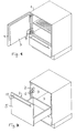
- FIG. 1 shows a kitchen cupboard according to the invention K with a heat compartment, which is in the body 1 is installed and has walls 3 made of stainless steel sheet, the door 4 also has a stainless steel cladding on its inside 3 wears.
- the closet adjustable shelf There is a common one in the closet adjustable shelf.
- the excerpt below of the closet has no direct relation to Invention, but only shows the possibility of the invention Cupboard with other usual elements as a base cabinet, tall cabinet, medium-high Cupboard, wall unit in a kitchen front in ergonomic integrate meaningful height.
- Fig.2 shows the training of the heat compartment as an extract, in a body 2 by means of (not shown) Rail is slidable and a front panel 5 with Handle bar 10 has.
- the interior walls of the body and Front panels are in turn each with a metal lining 3 provided.
- regulating or lighting elements 12 be arranged in the interior of the pull-out Display.
- the Metal lining 3 shows the structure of the metal lining 3 from individual elements with a narrow bevel 3 ', the Solvable according to the modular principle, e.g. by screws or stuck or fixed by welding, riveting can be put together, either in the manufacture of the kitchen cabinet or when retrofitting an existing one Kitchen cupboards as a heating compartment.
- the Metal lining 3 can be made of foil or stainless steel Steel or enamelled, powder-coated or with a temperature resistant Plastic coated steel sheet exist.
- Figure 4 shows schematically a side view, partially in the vertical section of the kitchen cabinet with Heat compartment of Figure 1, with the shelf replaced through a warming plate 9, which with a plug in a power outlet 8 in the Cabinet rear panel is insertable.
- door 4 has standard hinges attached to the cabinet body. Between body 1 and the metal lining 3 is an insulation 6 arranged, which improves the thermal insulation, the already through the wooden walls of the Body is given.
- Fig. 5 shows the hot plate schematically in perspective View.
- the warming plate is by means of their side handles easy and safe to handle.
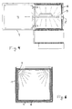
- Fig.6 shows a horizontal section through the Body of the cabinet of Fig. 1 and shows especially the heating rods arranged in the two rear corners 7 and its protective cover, which is an immediate Prevention of touching the heating rods by the user.
- Fig. 7 shows a detail of the kitchen front in the horizontal Cut.
- the metal lining 3 On the inside of the metal lining 3 the one with a standard hinge on the body held door 4, a sealing lip 13 is attached. How an electrical line 14 leads from the Handle bar 10 through the door and the insulation on the body, around existing display and switching elements with the power supply and the heating elements connect.
- Fig. 8 shows a side view of the floor in vertical Cut. Since the narrow fold 3 'of the metal lining 3 the chipboard forming the body 1 only touched over a small contact area, finds only one very little heat transfer instead.
- Fig. 9 shows schematically a partial view of a door or pull-out front with the handle bar 10 and in this integrated switches 11 and display elements 15.
- FIG. 10 shows schematically the training of the kitchen furniture according to the invention Heat or climate compartment as operated from two sides Room divider, with the kitchen furniture as a closet can be formed with opposite doors.
Landscapes
- Engineering & Computer Science (AREA)
- Chemical & Material Sciences (AREA)
- Combustion & Propulsion (AREA)
- Mechanical Engineering (AREA)
- General Engineering & Computer Science (AREA)
- Physics & Mathematics (AREA)
- Thermal Sciences (AREA)
- Life Sciences & Earth Sciences (AREA)
- Sustainable Development (AREA)
- Combinations Of Kitchen Furniture (AREA)
- Devices For Warming Or Keeping Food Or Tableware Hot (AREA)
- Electric Stoves And Ranges (AREA)
Description
So dient es zum:
- Vorwärmen von Tellern
- Warmhalten von Speisen
- Reifen von Teig
- Lagern von Tellern und Geschirr.
- Fig.1 eine schematische perspektivische Ansicht eines erfindungsgemäßen Küchenschranks mit Wärmefach;
- Fig.2 eine perspektivische Ansicht eines nicht zur Erfindung gehörenden Auszugs als Wärmefach;
- Fig.3 eine schematische Explosionszeichnung der Elemente aus denen die das Wärmefachgehäuse bildende Innenwandverkieidung zusammengesetzt ist;
- Fig.4 eine Seitenansicht bei aufgeklappter Tür und senkrechtem Schnitt durch den erfindungsgemäßen Küchenschrank mit Wärmefach und einer eingelegten Warmhalteplatte;
- Fig.5 eine perspektivische Ansicht der Warmhalteplatte der Fig.4;
- Fig.6 einen horizontalen Schnitt durch den Korpus und das Wärmefach der Fig.4 bei geschlossener Tür;
- Fig.7 eine Einzelheit der Scharnierverbindung von Korpus und Tür im horizontalen Schnitt;
- Fig.8 einen Teilschnitt durch den Boden des Wärmefachs in Seitenansicht;
- Fig.9 eine Einzelheit der Griffstange der Fig.7;
- Fig.10 einen schematischen Grundriß des erfindungsgemäßen Küchenschranks als Raumteiler.
Claims (8)
- Küchenfront mit einem Küchenmöbel in Form eines in die Küchenfront als Unterschrank, Hochschrank, mittelhoher Schrank, Oberschrank in ergonomisch sinnvoller Höhe integrierten Küchenschranks (K), mit zu den Einbauten der Küchenfront passender Front,
wobei die Innenflächen des Küchenschrank- Korpus (1,2) mit einer Metallauskleidung (3) versehen sind und der Küchenschrank mit einer Einrichtung zum Erwärmen und/oder Kühlen und/oder Gefrieren (Tiefkühlen) und/oder Belüften seines Innenraums versehen ist, um ein Wärme- oder Klimafach zu bilden,
wobei der Korpus (1, 2) selbst als Wärmeisolierung gegenüber den angrenzenden Möbelelementen dient,
wobei zwischen der Metallauskleidung (3) einerseits und dem Korpus (1,2) und der Türplatte (4) andererseits jeweils eine Isolation (6) vorgesehen ist, welche direkt an die Innenseiten des Korpus (1,2) und der Türplatte (4) angrenzt, und
wobei die Tür mit Standardbeschlägen am Korpus gehalten ist. - Küchenfront nach Anspruch 1, dadurch gekennzeichnet, daß die Metallauskleidung (3) aus Normteilen baukastenartig zusammengesetzt und in den Küchenschrank oder Auszugkorpus einsetzbar ist.
- Küchenfront nach einem der Ansprüche 1 oder 2, dadurch gekennzeichnet, daß die Metallauskleidung (3) aus Folie oder Blech aus rostfreiem Stahl oder Stahlblech, das pulverbeschichtet oder emailliert oder mit einer temperaturfesten Kunststoffbeschichtung versehen ist, besteht.
- Küchenfront nach einem der Ansprüche 1 bis 3, dadurch gekennzeichnet, daß im Innenraum wenigstens eine regelbare Heizvorrichtung (7) angeordnet ist.
- Küchenfront nach einem der Ansprüche 1 bis 4, dadurch gekennzeichnet, daß im Innenraum ein elektrischer Anschluß (8) für eine in den Innenraum einsetzbare elektrisch heizbare Warmhalteplatte (9) vorgesehen ist.
- Küchenfront mit einem Küchenmöbel nach einem der Ansprüche 1 bis 5, dadurch gekennzeichnet, daß der Küchenschrank mit zwei gegenüberliegenden Türen (4) ausgerüstet ist.
- Küchenfront mit einem Küchenmöbel nach einem der Ansprüche 1 bis 6, dadurch gekennzeichnet, daß die Einrichtung zum Erwärmen oder Kühlen oder Befeuchten regelbar ist und zur Regelung dienende Schalter (11) an oder in einer Griffstange (10) der Tür (4) angeordnet sind.
- Küchenfront mit einem Küchenmöbel nach einem der Ansprüche 1 bis 7, dadurch gekennzeichnet, daß die Metallauskleidung (3) schmale Abkantungen (3') aufweist, welche die Isolation (6) überdecken und nur ganz geringe Wärmeübertragung zulassen.
Applications Claiming Priority (2)
| Application Number | Priority Date | Filing Date | Title |
|---|---|---|---|
| DE19934337363 DE4337363C1 (de) | 1993-11-02 | 1993-11-02 | Küchenmöbel mit Klimafach, besonders Wärmefach |
| DE4337363 | 1993-11-02 |
Publications (3)
| Publication Number | Publication Date |
|---|---|
| EP0650679A1 EP0650679A1 (de) | 1995-05-03 |
| EP0650679B1 EP0650679B1 (de) | 1997-01-29 |
| EP0650679B2 true EP0650679B2 (de) | 2002-10-02 |
Family
ID=6501611
Family Applications (1)
| Application Number | Title | Priority Date | Filing Date |
|---|---|---|---|
| EP94115749A Expired - Lifetime EP0650679B2 (de) | 1993-11-02 | 1994-10-06 | Küchenmöbel mit Klimafach, besonders Wärmefach |
Country Status (2)
| Country | Link |
|---|---|
| EP (1) | EP0650679B2 (de) |
| DE (1) | DE4337363C1 (de) |
Cited By (2)
| Publication number | Priority date | Publication date | Assignee | Title |
|---|---|---|---|---|
| EP1640668A2 (de) | 2004-09-23 | 2006-03-29 | Miele & Cie. KG | Griffstange für ein Haushaltsgerät, insbesondere Herd oder Backofen |
| CN100385188C (zh) * | 2004-08-26 | 2008-04-30 | Lg电子株式会社 | 具有篮筐升降装置的冰箱 |
Families Citing this family (8)
| Publication number | Priority date | Publication date | Assignee | Title |
|---|---|---|---|---|
| DE4337363C1 (de) * | 1993-11-02 | 1994-07-28 | Bulthaup Gmbh & Co | Küchenmöbel mit Klimafach, besonders Wärmefach |
| DE29506735U1 (de) * | 1995-04-20 | 1995-06-14 | Holland Kühlmöbel K. & M. Holland GmbH, 94327 Bogen | Theke mit eingebauter Kühleinrichtung, insbesondere für Gastronomiebetriebe |
| AU709558B3 (en) * | 1998-09-25 | 1999-09-02 | Ozline Group Pty. Limited | Heating apparatus |
| AUPQ688900A0 (en) * | 2000-04-13 | 2000-05-11 | Burnell, Robert Dennis George | Heating apparatus |
| DE10045236B4 (de) * | 2000-09-13 | 2013-08-22 | BSH Bosch und Siemens Hausgeräte GmbH | Geschirrspülmaschine für den Einbau hinter einer Möbelfrontplatte |
| DE10125505A1 (de) | 2001-05-23 | 2003-01-16 | Alno Ag | Küchenelement mit Warmhaltemittel |
| DE10235918B4 (de) * | 2002-08-01 | 2004-08-19 | Bernhard Kaluza | Montagesystem für Möbel und Verfahren zur Montage von Möbeln |
| NZ546385A (en) * | 2003-09-05 | 2009-11-27 | Mrs Mac S Pty Ltd | Method for maintaining hot food and/or heating cold food by monitoring the surface on which the food is placed |
Citations (3)
| Publication number | Priority date | Publication date | Assignee | Title |
|---|---|---|---|---|
| DE1429854A1 (de) † | 1965-06-08 | 1969-06-19 | Ludwig Clemencon | Verfahren zum Kochen von Speisen in einer Kochkiste und Vorrichtung zur Durchfuehrung des Verfahrens |
| DE1554464C3 (de) † | 1965-09-25 | 1978-10-26 | Schaffitzel, Helmut, 7170 Schwaebisch Hall | |
| DE8200623U1 (de) † | 1982-01-14 | 1982-07-15 | Celltherm Isolierung Gmbh & Co Kg, 4432 Gronau | Tafelfoermige isolierpaneele fuer kuehl- und gefrierzellen |
Family Cites Families (9)
| Publication number | Priority date | Publication date | Assignee | Title |
|---|---|---|---|---|
| DE861741C (de) * | 1951-09-23 | 1953-01-05 | Homann Werke Wilhelm Homann | Schrank- oder kastenfoermiger Behaelter fuer Haushalts-, insbesondere Kuechenzwecke |
| DE2757951C2 (de) * | 1977-12-24 | 1982-10-07 | Licentia Patent-Verwaltungs-Gmbh, 6000 Frankfurt | Einbauhaushaltgerät mit Beheizung |
| FR2510384B1 (fr) * | 1981-08-03 | 1986-01-10 | Fritsch Sa | Dispositif de remise en temperature des aliments disposes sur des plateaux individuels avec regeneration integree |
| DE3429146A1 (de) * | 1984-08-08 | 1986-02-13 | Erich 7800 Freiburg Merbreier | Kuechenmoebel |
| CH668894A5 (de) * | 1987-03-30 | 1989-02-15 | Berndorf Luzern Ag | Vorrichtung zum kuehlen, aufbewahren und wiedererwaermen von kompletten mahlzeiten. |
| AU2016592A (en) * | 1991-05-31 | 1993-01-08 | Beltec International | Cabinet-style apparatus for transferring heat to food |
| US5240320A (en) * | 1991-10-11 | 1993-08-31 | Crescent Metal Products, Inc. | Food service cabinet |
| DE9113763U1 (de) * | 1991-11-05 | 1991-12-19 | Bulthaup GmbH & Co, 8318 Aich | Griffstange mit elektrischer Schaltvorrichtung, besonders für eine Dunstabzugshaube |
| DE4337363C1 (de) * | 1993-11-02 | 1994-07-28 | Bulthaup Gmbh & Co | Küchenmöbel mit Klimafach, besonders Wärmefach |
-
1993
- 1993-11-02 DE DE19934337363 patent/DE4337363C1/de not_active Expired - Fee Related
-
1994
- 1994-10-06 EP EP94115749A patent/EP0650679B2/de not_active Expired - Lifetime
Patent Citations (3)
| Publication number | Priority date | Publication date | Assignee | Title |
|---|---|---|---|---|
| DE1429854A1 (de) † | 1965-06-08 | 1969-06-19 | Ludwig Clemencon | Verfahren zum Kochen von Speisen in einer Kochkiste und Vorrichtung zur Durchfuehrung des Verfahrens |
| DE1554464C3 (de) † | 1965-09-25 | 1978-10-26 | Schaffitzel, Helmut, 7170 Schwaebisch Hall | |
| DE8200623U1 (de) † | 1982-01-14 | 1982-07-15 | Celltherm Isolierung Gmbh & Co Kg, 4432 Gronau | Tafelfoermige isolierpaneele fuer kuehl- und gefrierzellen |
Cited By (2)
| Publication number | Priority date | Publication date | Assignee | Title |
|---|---|---|---|---|
| CN100385188C (zh) * | 2004-08-26 | 2008-04-30 | Lg电子株式会社 | 具有篮筐升降装置的冰箱 |
| EP1640668A2 (de) | 2004-09-23 | 2006-03-29 | Miele & Cie. KG | Griffstange für ein Haushaltsgerät, insbesondere Herd oder Backofen |
Also Published As
| Publication number | Publication date |
|---|---|
| EP0650679B1 (de) | 1997-01-29 |
| EP0650679A1 (de) | 1995-05-03 |
| DE4337363C1 (de) | 1994-07-28 |
Similar Documents
| Publication | Publication Date | Title |
|---|---|---|
| DE19757004C2 (de) | Kochzentrum mit Warm- und/oder Kaltausgabe | |
| EP0650679B2 (de) | Küchenmöbel mit Klimafach, besonders Wärmefach | |
| EP1528327A2 (de) | Gargerät | |
| DE3015286A1 (de) | Back- und/oder brateinrichtung | |
| DE10116098A1 (de) | Küchensystem | |
| DE3814253A1 (de) | Haushalt-mikrowellenofen fuer den einbau oder die aufstellung unterhalb des niveaus der arbeitsflaeche | |
| DE6609356U (de) | Kuehlschrank, insbesondere fuer wohnwagen. | |
| EP4414616A1 (de) | Dampfgarschublade | |
| DE10204214B4 (de) | Warmhalteplatte | |
| DE202014101367U1 (de) | Mobiles Küchensystem | |
| DE29722573U1 (de) | Kochzentrum mit Warm- und/oder Kaltausgabe | |
| DE1554464C3 (de) | ||
| DE8905998U1 (de) | Gargerät | |
| DE8713982U1 (de) | Kombinations-Küchengerät mit Backofen und Mikrowellenherd | |
| DE630354C (de) | Kocheinrichtung fuer Wohnkuechen u. dgl. | |
| BE1031289B1 (de) | Küchengerät | |
| DE4436607A1 (de) | Einbauküche mit Herd | |
| DE102008009248A1 (de) | Vorrichtung zum Zubereiten, Aufbewahren oder Ausgeben von Speisen | |
| DE29722103U1 (de) | Kochfeldanordnung | |
| DE815079C (de) | Elektrischer Wandherd | |
| BE1029169B1 (de) | Gargerät, vorzugsweise Einbaugargerät | |
| DE3104712C2 (de) | Herd mit frontseitigem Lüftungsrost | |
| DE10059653C1 (de) | Ofen, insbesondere zum Garen von Speisen | |
| DE4323659A1 (de) | Vielseitig einsetzbares, kompaktes Gar- und Backgerät | |
| EP0697567A1 (de) | Kombinationseinrichtung zum Zubereiten warmer Speisen |
Legal Events
| Date | Code | Title | Description |
|---|---|---|---|
| PUAI | Public reference made under article 153(3) epc to a published international application that has entered the european phase |
Free format text: ORIGINAL CODE: 0009012 |
|
| AK | Designated contracting states |
Kind code of ref document: A1 Designated state(s): CH FR IT LI |
|
| 17P | Request for examination filed |
Effective date: 19950511 |
|
| GRAG | Despatch of communication of intention to grant |
Free format text: ORIGINAL CODE: EPIDOS AGRA |
|
| GRAH | Despatch of communication of intention to grant a patent |
Free format text: ORIGINAL CODE: EPIDOS IGRA |
|
| 17Q | First examination report despatched |
Effective date: 19960702 |
|
| GRAH | Despatch of communication of intention to grant a patent |
Free format text: ORIGINAL CODE: EPIDOS IGRA |
|
| GRAA | (expected) grant |
Free format text: ORIGINAL CODE: 0009210 |
|
| AK | Designated contracting states |
Kind code of ref document: B1 Designated state(s): CH FR IT LI |
|
| PG25 | Lapsed in a contracting state [announced via postgrant information from national office to epo] |
Ref country code: FR Free format text: LAPSE BECAUSE OF NON-PAYMENT OF DUE FEES Effective date: 19970129 |
|
| REG | Reference to a national code |
Ref country code: CH Ref legal event code: EP |
|
| RAP2 | Party data changed (patent owner data changed or rights of a patent transferred) |
Owner name: BULTHAUP GMBH & CO. KUECHENSYSTEME |
|
| ITF | It: translation for a ep patent filed | ||
| ET | Fr: translation filed | ||
| PLBQ | Unpublished change to opponent data |
Free format text: ORIGINAL CODE: EPIDOS OPPO |
|
| PLBI | Opposition filed |
Free format text: ORIGINAL CODE: 0009260 |
|
| PLBF | Reply of patent proprietor to notice(s) of opposition |
Free format text: ORIGINAL CODE: EPIDOS OBSO |
|
| 26 | Opposition filed |
Opponent name: BLANCO GMBH & CO. KG Effective date: 19971028 |
|
| PLBF | Reply of patent proprietor to notice(s) of opposition |
Free format text: ORIGINAL CODE: EPIDOS OBSO |
|
| PLBF | Reply of patent proprietor to notice(s) of opposition |
Free format text: ORIGINAL CODE: EPIDOS OBSO |
|
| PLBF | Reply of patent proprietor to notice(s) of opposition |
Free format text: ORIGINAL CODE: EPIDOS OBSO |
|
| PLBF | Reply of patent proprietor to notice(s) of opposition |
Free format text: ORIGINAL CODE: EPIDOS OBSO |
|
| PGFP | Annual fee paid to national office [announced via postgrant information from national office to epo] |
Ref country code: FR Payment date: 19991029 Year of fee payment: 6 |
|
| PLAW | Interlocutory decision in opposition |
Free format text: ORIGINAL CODE: EPIDOS IDOP |
|
| APAC | Appeal dossier modified |
Free format text: ORIGINAL CODE: EPIDOS NOAPO |
|
| APAE | Appeal reference modified |
Free format text: ORIGINAL CODE: EPIDOS REFNO |
|
| APAC | Appeal dossier modified |
Free format text: ORIGINAL CODE: EPIDOS NOAPO |
|
| REG | Reference to a national code |
Ref country code: FR Ref legal event code: ST |
|
| PGFP | Annual fee paid to national office [announced via postgrant information from national office to epo] |
Ref country code: CH Payment date: 20011029 Year of fee payment: 8 |
|
| APAC | Appeal dossier modified |
Free format text: ORIGINAL CODE: EPIDOS NOAPO |
|
| PLAW | Interlocutory decision in opposition |
Free format text: ORIGINAL CODE: EPIDOS IDOP |
|
| PUAH | Patent maintained in amended form |
Free format text: ORIGINAL CODE: 0009272 |
|
| STAA | Information on the status of an ep patent application or granted ep patent |
Free format text: STATUS: PATENT MAINTAINED AS AMENDED |
|
| RAP2 | Party data changed (patent owner data changed or rights of a patent transferred) |
Owner name: BULTHAUP GMBH & CO. KG |
|
| 27A | Patent maintained in amended form |
Effective date: 20021002 |
|
| AK | Designated contracting states |
Kind code of ref document: B2 Designated state(s): CH FR IT LI |
|
| PG25 | Lapsed in a contracting state [announced via postgrant information from national office to epo] |
Ref country code: LI Free format text: LAPSE BECAUSE OF NON-PAYMENT OF DUE FEES Effective date: 20021031 Ref country code: CH Free format text: LAPSE BECAUSE OF NON-PAYMENT OF DUE FEES Effective date: 20021031 |
|
| REG | Reference to a national code |
Ref country code: CH Ref legal event code: AEN Free format text: AUFRECHTERHALTUNG DES PATENTES IN GEAENDERTER FORM |
|
| REG | Reference to a national code |
Ref country code: CH Ref legal event code: PL |
|
| EN | Fr: translation not filed | ||
| APAH | Appeal reference modified |
Free format text: ORIGINAL CODE: EPIDOSCREFNO |
|
| PG25 | Lapsed in a contracting state [announced via postgrant information from national office to epo] |
Ref country code: IT Free format text: LAPSE BECAUSE OF NON-PAYMENT OF DUE FEES;WARNING: LAPSES OF ITALIAN PATENTS WITH EFFECTIVE DATE BEFORE 2007 MAY HAVE OCCURRED AT ANY TIME BEFORE 2007. THE CORRECT EFFECTIVE DATE MAY BE DIFFERENT FROM THE ONE RECORDED. Effective date: 20051006 |