EP0640183B1 - Machine hydrostatique avec evacuation de l'huile de fuite - Google Patents
Machine hydrostatique avec evacuation de l'huile de fuite Download PDFInfo
- Publication number
- EP0640183B1 EP0640183B1 EP93909853A EP93909853A EP0640183B1 EP 0640183 B1 EP0640183 B1 EP 0640183B1 EP 93909853 A EP93909853 A EP 93909853A EP 93909853 A EP93909853 A EP 93909853A EP 0640183 B1 EP0640183 B1 EP 0640183B1
- Authority
- EP
- European Patent Office
- Prior art keywords
- leakage oil
- pump
- machine according
- hydrostatic machine
- pump device
- Prior art date
- Legal status (The legal status is an assumption and is not a legal conclusion. Google has not performed a legal analysis and makes no representation as to the accuracy of the status listed.)
- Expired - Lifetime
Links
Images

Classifications
-
- F—MECHANICAL ENGINEERING; LIGHTING; HEATING; WEAPONS; BLASTING
- F04—POSITIVE - DISPLACEMENT MACHINES FOR LIQUIDS; PUMPS FOR LIQUIDS OR ELASTIC FLUIDS
- F04B—POSITIVE-DISPLACEMENT MACHINES FOR LIQUIDS; PUMPS
- F04B53/00—Component parts, details or accessories not provided for in, or of interest apart from, groups F04B1/00 - F04B23/00 or F04B39/00 - F04B47/00
- F04B53/04—Draining
-
- F—MECHANICAL ENGINEERING; LIGHTING; HEATING; WEAPONS; BLASTING
- F04—POSITIVE - DISPLACEMENT MACHINES FOR LIQUIDS; PUMPS FOR LIQUIDS OR ELASTIC FLUIDS
- F04B—POSITIVE-DISPLACEMENT MACHINES FOR LIQUIDS; PUMPS
- F04B1/00—Multi-cylinder machines or pumps characterised by number or arrangement of cylinders
- F04B1/12—Multi-cylinder machines or pumps characterised by number or arrangement of cylinders having cylinder axes coaxial with, or parallel or inclined to, main shaft axis
- F04B1/20—Multi-cylinder machines or pumps characterised by number or arrangement of cylinders having cylinder axes coaxial with, or parallel or inclined to, main shaft axis having rotary cylinder block
- F04B1/2014—Details or component parts
-
- F—MECHANICAL ENGINEERING; LIGHTING; HEATING; WEAPONS; BLASTING
- F04—POSITIVE - DISPLACEMENT MACHINES FOR LIQUIDS; PUMPS FOR LIQUIDS OR ELASTIC FLUIDS
- F04B—POSITIVE-DISPLACEMENT MACHINES FOR LIQUIDS; PUMPS
- F04B23/00—Pumping installations or systems
- F04B23/04—Combinations of two or more pumps
- F04B23/08—Combinations of two or more pumps the pumps being of different types
- F04B23/10—Combinations of two or more pumps the pumps being of different types at least one pump being of the reciprocating positive-displacement type
- F04B23/106—Combinations of two or more pumps the pumps being of different types at least one pump being of the reciprocating positive-displacement type being an axial piston pump
-
- F—MECHANICAL ENGINEERING; LIGHTING; HEATING; WEAPONS; BLASTING
- F04—POSITIVE - DISPLACEMENT MACHINES FOR LIQUIDS; PUMPS FOR LIQUIDS OR ELASTIC FLUIDS
- F04B—POSITIVE-DISPLACEMENT MACHINES FOR LIQUIDS; PUMPS
- F04B23/00—Pumping installations or systems
- F04B23/04—Combinations of two or more pumps
- F04B23/08—Combinations of two or more pumps the pumps being of different types
- F04B23/14—Combinations of two or more pumps the pumps being of different types at least one pump being of the non-positive-displacement type
-
- F—MECHANICAL ENGINEERING; LIGHTING; HEATING; WEAPONS; BLASTING
- F16—ENGINEERING ELEMENTS AND UNITS; GENERAL MEASURES FOR PRODUCING AND MAINTAINING EFFECTIVE FUNCTIONING OF MACHINES OR INSTALLATIONS; THERMAL INSULATION IN GENERAL
- F16N—LUBRICATING
- F16N7/00—Arrangements for supplying oil or unspecified lubricant from a stationary reservoir or the equivalent in or on the machine or member to be lubricated
- F16N7/14—Arrangements for supplying oil or unspecified lubricant from a stationary reservoir or the equivalent in or on the machine or member to be lubricated the lubricant being conveyed from the reservoir by mechanical means
- F16N7/16—Arrangements for supplying oil or unspecified lubricant from a stationary reservoir or the equivalent in or on the machine or member to be lubricated the lubricant being conveyed from the reservoir by mechanical means the oil being carried up by a lifting device
- F16N7/18—Arrangements for supplying oil or unspecified lubricant from a stationary reservoir or the equivalent in or on the machine or member to be lubricated the lubricant being conveyed from the reservoir by mechanical means the oil being carried up by a lifting device with one or more feed members fixed on a shaft
Definitions
- the invention relates to a hydrostatic machine, in particular an axial piston machine, with a machine housing, the housing interior of which accommodates a rotatably mounted engine and comprises a leakage oil chamber which opens outwards via at least one leakage oil connection and which receives leakage oil, including lubricating oil, which flows away from bearing points of the hydrostatic machine , and with a pump device arranged in a rotationally fixed manner, which pumps out leakage oil to the outside through the leakage oil connection, a certain leakage oil level being established in the lower region of the leakage oil chamber.
- Such a hydrostatic machine is known from FR-A 2 145 741, the pump device of which comprises a gearwheel immersed in the leak oil and an element fastened to the bottom of the machine housing with a groove into which the part of the gearwheel immersed in the leak oil has little lateral play intervenes.
- the groove bottom runs concentrically to the gearwheel and has a vertical step that divides the groove into two groove sections with corresponding groove bottom sections.
- the rear groove bottom section assigned to the gearwheel outlet from the groove has a small distance and the remaining groove bottom section has a greater distance from the outer circumference of the gearwheel.
- the drain port is located at the lowest point of the latter groove bottom section.
- the leakage oil level set in the leakage oil chamber depends on the leakage oil quantity flowing into the leakage oil chamber per unit of time, which in turn depends on the operating conditions of the hydrostatic machine, in particular on the pressure difference at its leakage gaps and their connections and on their speed, on the speed of the hydrostatic machine, ie of the amount of leakage oil carried into the groove by the gearwheel, and of the geometric dimensions of the rear groove section in particular relative to the gearwheel, ie of the amount of leakage oil emerging from the groove.
- These dependencies are very complex and prevent the setting of a constant leakage oil level and thus a constant reduction of the splashing losses, which increase, for example, with increasing pressure difference and increasing speed of the hydrostatic machine.
- the leakage oil quantity overflowing from the leakage oil space over the free edge of the annular boundary is pumped out completely by the pump device due to its correspondingly high delivery capacity under all operating conditions, i.e. independent of pressure and speed, so that a leakage oil level is obtained which corresponds to the height of the free edge of the annular boundary corresponds.
- the leakage oil level depends only on the position of the free edge of the annular boundary; the influence of the speed of the pumping device is switched off because of its Delivery rate is greater than the amount of leakage oil flowing into the leakage oil chamber under all operating conditions per unit of time.
- the position of the free edge of the ring-shaped boundary is chosen so that either the splash losses exceeding the mechanical losses of the hydrostatic machine or all splash losses are avoided. In the latter case, the leakage oil level is preferably below the engine.
- a pump device which runs in the form of a radial bore in the drive shaft of an axial piston machine, but which is not suitable for pumping out leak oil from the leak oil chamber.
- a pressure pump supplies the axial piston machine with pressurized oil on the input side. This overpressure prevails via a corresponding connection in the leakage oil chamber of the axial piston machine, which is connected via a throttle, an axial bore and the radial bore, which represents the pumping device, in the drive shaft to a swashplate space, which opens outwards via a leakage oil connection and in which the swash plate and return springs are arranged to return the pistons against the inlet pressure.
- the flow cross-section of the throttle is dimensioned such that there is sufficient oil circulation for the lubrication of the moving parts in the swash plate space, even at zero flow, which is supported by the centrifugal effect which the rotating drive shaft has on the flowing through the radial bore and in the swash plate space over 360 ° distributed oil.
- the flow cross-section of the leakage oil connection is larger than that of the throttle, so that a lower pressure is established in the swashplate chamber than in the leakage oil chamber, which according to the task does not impair the function of the return springs in the swashplate chamber.
- This pressure in the swash plate area corresponds to the position of the drain port and the flow resistance in the connected drain line.
- the leakage oil chamber and the swashplate chamber of this known hydrostatic machine are consequently filled with leakage oil which is under pressure and which causes churning losses when the engine rotates.
- the annular boundary dividing the suction area of the pump device is preferably an annular diaphragm.
- This ring diaphragm can be one of two essentially radially extending annular boundaries, which are arranged on both sides of the pump device and, together with the section of the machine housing located between them, form a pump housing.
- the pump device is expediently a centrifugal pump, which can comprise a blade wheel with radially extending or curved blades, which are arranged in a rotationally fixed manner on the outer circumference of the engine and / or on a free end face thereof.
- the pump device is arranged eccentrically to the machine housing, forming an annular space that is crescent-shaped in radial section, the leakage oil connection opening into the annular space region of the larger radial dimension.
- the velocity energy of the leaked oil sucked out of the leaked oil space and accelerated in the pumping device is converted into pressure in the annular space area of the larger radial dimension, which acts as a diffuser, in order to overcome flow resistances in the leaked oil line connected to the leaked oil connection and the pressure level to the tank.
- the pump device can be assigned a guide vane arrangement which likewise converts the speed energy of the leakage oil flow into pressure in the pump device.
- the pump device can be designed as a friction pump, which is a very small one has design effort. It preferably comprises at least one pump surface that rotates with the engine, the pumping effect of which is based on the entrainment of the friction layer of the leakage oil to be pumped that adheres to it.
- This pump surface can be a cylindrical pump surface formed on the engine, for example on its outer circumference, or a flat pump surface extending in a radial plane perpendicular to the engine, preferably on a free end face of the engine. Each pump surface is expediently roughened or structured in order to improve the delivery rate.
- the flat pump surface is expediently formed on a free end face of a drive pulley of the engine.
- the leak oil connection is advantageously formed with an axial distance from the flat pump surface in the area covered by the drive pulley.
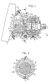
- the hydrostatic machine shown in FIGS. 1 and 4 is an axial piston machine with an inclined axis construction of basically conventional construction. It is intended for horizontal installation and comprises a machine housing 1 and an engine rotatably arranged in the interior of the housing, which according to the invention is provided with a pump device 29 or 50.
- the otherwise cylindrical machine housing 1 is expanded on one side in such a way that the radius of the upper half of the cross section of the housing, which runs vertically in FIG. 2, increases continuously with a constant radius of the lower half of the cross section of the housing and corresponding transitions between the two radii in the direction of an end plate 2.
- the machine housing 1 comprises a cylindrical housing part and a housing part which is elliptical in cross section.
- the engine comprises a drive shaft 3 and a cylinder drum 4.
- the drive shaft 3 is rotatably supported in the cylindrical housing part by means of two tapered roller bearings 5, 6 and ends in the beginning region of the housing part which is elliptical in cross section with a flange-like section of larger diameter representing a drive disk 7, the plane of rotation of which is represented by a Leakage oil connection 8 in the machine housing 1 goes in the top vertex region in the drawing.
- a leakage oil line, not shown, leads from the leakage oil connection 8 to the tank, also not shown.
- the drive pulley 7 is arranged in the immediate vicinity of the tapered roller bearing 5.
- Each tapered roller bearing 5, 6 consists of an inner ring 9 attached to the drive shaft 3, an outer ring 10 attached to the machine housing 1 and tapered rollers 11 located between them.
- the cylinder drum 4 is rotatably mounted on a control body 12 in the cross-sectionally elliptical part of the machine housing 1.
- This bearing is self-centering; for this purpose the bearing surfaces of the cylinder drum 4 and the control body 12, e.g. shown in Figure 1, spherical with a concave or convex shape.
- the control body 12 is slidably arranged in a circular support and pivot bearing 13 in the end plate 2 and can be fixed within this bearing by means of an actuating device 14 in any desired position.
- two opposing control kidneys, not shown, are formed in a known manner, which are connected to a pressure port and a suction port (also not shown) of the axial piston machine.
- cylindrical spaces 15 are formed, which open out via cylinder channels 16 on the bearing surface of the cylinder drum 4 supported on the control body 12 and when the latter rotates, the cylinder spaces 15 with the pressure and the Connect the suction nozzle.
- Pistons 17 are arranged so that they can be moved back and forth in the cylinder spaces 15. Their piston rods can be rotatably driven with the drive pulley via ball joints 18 7 connected.
- a compression spring 19 is seated in a central blind bore in the cylinder drum 4, which is supported against a central pin 20, which is also connected to the drive pulley 7 by means of a ball joint 18 and projects into the blind bore, and in this way the cylinder drum 4, when no oil pressure forces occur, in contact holds to the control body 12.
- the blind bore opens out via an oil channel 21 on the bearing surface of the cylinder drum 4.
- This oil channel 21 supplies via an axial through bore 22 in the middle journal 20, a further axial bore 23 in the drive shaft 3, a circumferential groove 24 formed in the same in a radial plane between the two tapered roller bearings 5,6 and radial bores 25 in the same radial plane both tapered roller bearings 5,6 for lubrication with pressure oil from the internal oil circuit of the axial piston machine.
- the oil supply to the ball joints 18 also takes place from the internal oil circuit via the through hole 22 in the center pin 20 and via substantially the same, also designated by the reference numeral 22, axial through holes in the piston 17th
- a flushing oil connection 26 in the cylindrical housing part of the machine housing 1 is connected for the purpose of additional lubricating oil supply to the tapered roller bearings 5, 6 via an annular channel arrangement 27 with the radial bores 25 and the side of the tapered roller bearing 6 facing away from the drive pulley 7.
- the part of the housing interior which is not filled by the engine 3, 4, 7 serves as a leak oil chamber 28 for receiving the leak oil that occurs during operation of the axial piston machine.
- the leak oil chamber 28 is connected to the tank, also not shown, via the leak oil connection 8 and a further leak oil line, not shown.
- the machine housing 1 has a ventilation connection, not shown, which leads via a ventilation line, also not shown, to a ventilation valve (not shown).
- the pump device 29 shown in FIGS. 1 and 2 is a flow pump in the form of a paddle wheel 29 with curved blades 36, which is attached to the circumference of the drive pulley 7 and has a radially extending fastening flange 30, by means of which it is fastened to the free end face of the drive pulley 7 by means of screws 31.
- a radially extending limit is attached to the machine housing 1.
- One of the boundaries is formed by the outer ring 10 and the tapered rollers 11 of the tapered roller bearing 5 adjacent to the drive pulley 7 and the other boundary by an annular diaphragm 32 which is arranged in the region between the cylinder drum 4 and the drive pulley 7 and at a distance from the imaginary, the whole the cylinder surface circumscribing from the cylinder drum 4 protruding piston rods ends.
- the annular gap corresponding to this distance is designated by reference numeral 33.
- Both limits 10, 11 and 32 and the section 34 of the machine housing 1 located between them form a pump housing for the impeller 29 within the leakage oil chamber 28.
- annular space 35 which, due to the course of the machine housing section 34 at an angle to the longitudinal axis L of the axial piston machine or the engine 3, 4, 7, is crescent-shaped in the radial section and in its annular space area Largest radial dimension of the drain port 8 opens (see Fig. 2).
- the leakage oil inflow to the paddle wheel 29 takes place in the axial direction, on the one hand, via the tapered roller bearing 5 essentially over its entire circumference and, on the other hand, via the annular gap 33.
- a housing opening 38 in the machine housing 1, which is closed by a screw plug 37, is formed diametrically to the leakage oil connection 8.
- FIGS. 1 and 2 Since the function of the hydrostatic machine shown is known to the person skilled in the art and a description thereof is therefore unnecessary, only the function of the pump device 29 according to FIGS. 1 and 2 is explained below.
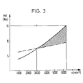
- Contain wobble loss portion which is caused by the rotation of the engine in the leak oil located within the leak oil chamber 28 and in Figure 3 with the solid Line is shown.
- FIG. 3 also shows with the dash-dotted line the dependence of the remaining, predominantly mechanical, loss portion that would occur in the leak-oil-free leak oil chamber 28 when the engine rotated. It can be seen that in the lower speed range up to 3000 min ⁇ 1 (about half of the maximum permissible speed of 6300 min ⁇ 1) the splash loss share is smaller and in the upper speed range above 3000 min ⁇ 1 larger than the remaining loss share.
- leakage oil occurs from the internal oil circuit of the hydrostatic machine primarily via the ball joints 18 and via the bearing formed by the bearing surfaces of the cylinder drum 4 and the control body 12 into the leakage oil chamber 28 and flows therefrom via the Ring diaphragm 33 axially toward the impeller 29.
- the oil also supplied to the tapered roller bearings 5, 6 from the internal oil circuit and, if appropriate, from the flushing oil connection 26 also flows axially via the tapered roller bearing 5 to the impeller 29. All of the incoming oil is guided radially from the inside to the outside within the impeller 29, which acts as a centrifugal pump, and is accelerated in accordance with the rotation of the impeller 29.
- the speed energy supplied to the oil is converted into pressure in the annular space 35, in particular in the area of its greatest radial dimension. As soon as the pressure is sufficiently high to overcome the friction losses in the leakage oil line leading to the tank and the pressure level to the tank, if this is arranged in a plane above the hydrostatic machine, the leakage oil is pumped out via the leakage oil connection 8.
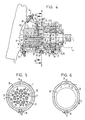
- the pump device 50 shown in Figures 4 to 6 is also a centrifugal flow pump with radially extending blades 50, which can either be assembled into a paddle wheel or, as shown here, each in one piece with a vertically projecting mounting plate 51 and by means of this Fastening screws 31 are fastened to the free end face of the drive pulley 7 facing the cylinder drum 4.
- This pump device 50 which has the same function as that according to FIGS. 1 and 2, is assigned a guide vane arrangement with (in this exemplary embodiment) three stationary guide vanes 52 which are inserted in the area of the leakage oil connection 8 in the ring diaphragm 32 (see FIG. 6 ).
- the guide vane arrangement 52 has essentially the same pressure conversion task as the area of greatest radial dimension of the crescent-shaped annular space 35 according to FIGS. 1 and 2 and can therefore be arranged in an annular space of constant annular width instead of in such a crescent-shaped annular space 35, as shown in FIGS. 5 and 6.
- the guide vanes 52 as well as the vanes 36, 50 are adapted to the different operating conditions with regard to their number, size, design and their course in order to optimize their function.
- the axial piston machine shown in detail in FIG. 7 differs from that of FIG. 1 with an otherwise identical construction and function by a pump device 60 designed as a friction pump, an annular space 61 of constant ring width created by corresponding adaptation of the machine housing 1, and one in the lower vertex region of the machine housing 1 axial distance from the free end face of the drive pulley 7 in the leakage oil connection formed by this covered area, namely the housing opening 38.
- the friction pump consists of a pump surface 60 in the form of an annular surface section of the free end face of the drive pulley 7 in its radial edge area.
- the pumping action of this friction pump is based on the entrainment of the friction layer of the leakage oil to be pumped, which friction layer adheres to its pump surface 60 and which accelerates radially outwards at the appropriate speed of the engine 3, 4, 7 and in the same way as with the flow pump 29 via the annular space 61 and via the Drain oil connection 38 (or any other housing opening) is pumped out.
- the (radial) ring width of the annular space 61 is larger than the thickness of the friction layer.
- a guide vane arrangement can also be used and / or the annular space 35 and the leakage oil connection 8 according to FIG. 1 can be used.
- the pump surface 60 is structured, for example roughened. Their distance from the ring diaphragm 32 is greater than the thickness of the friction layer.
Abstract
Claims (18)
- Machine hydrostatique, en particulier machine à piston axial, comportant un carter de machine, dont le volume intérieur de carter loge un mécanisme moteur monté tournant et comprend une chambre d'huile de fuite débouchant vers l'extérieur par au moins un raccord d'huile de fuite, laquelle chambre contient de l'huile de fuite, y compris de l'huile de lubrification, qui s'écoule de points d'appui de la machine hydrostatique, et un dispositif à pompe, placé solidaire en rotation sur le mécanisme moteur, qui pompe l'huile de fuite vers l'extérieur à travers le raccord d'huile de fuite, un niveau d'huile de fuite déterminé s'établissant dans la partie inférieure de la chambre d'huile de fuite, caractérisée par une délimitation (32) annulaire, qui partage une zone d'aspiration axiale du dispositif à pompe (29 ; 50 ; 60) dans la partie intérieure de la chambre d'huile de fuite (28), est fixée sur le carter de machine (1) et se termine à distance de celui-ci avec un bord libre, qui sert de trop-plein pour l'huile de fuite, de la chambre d'huile de fuite (28) vers la zone d'aspiration et détermine le niveau (N) de l'huile de fuite dans la chambre d'huile de fuite (28), niveau (N) auquel il ne se produit au moins aucune perte par barbotage dépassant les pertes mécaniques de la machine hydrostatique par suite de la rotation du mécanisme moteur (3, 4, 7) dans l'huile de fuite.
- Machine hydrostatique selon la revendication 1, caractérisée en ce que le niveau (N) se trouve au-dessous du mécanisme moteur (3, 4, 7).
- Machine hydrostatique selon la revendication 1 ou 2, caractérisée en ce que le dispositif à pompe comprend une pompe d'écoulement (29 ; 50 ; 60).
- Machine hydrostatique selon la revendication 3, caractérisée en ce que le dispositif à pompe comprend une pompe centrifuge (29 ; 50 ; 60).
- Machine hydrostatique selon la revendication 3 ou 4, caractérisée en ce que le dispositif à pompe comprend une roue à pales (29 ; 50).
- Machine hydrostatique selon la revendication 5, caractérisée en ce que le dispositif à pompe (29) comprend des pales (36) placées solidaires en rotation sur le pourtour extérieur du mécanisme moteur (3, 4, 7).
- Machine hydrostatique selon la revendication 5 ou 6, caractérisée en ce que le dispositif à pompe (50) comprend des pales (50) placées solidaires en rotation sur un côté frontal du mécanisme moteur (3, 4, 7).
- Machine hydrostatique selon l'une au moins des revendications précédentes, caractérisée en ce que le dispositif à pompe comprend une pompe à friction (60) avec au moins une surface de pompe (60) tournant avec le mécanisme moteur (3, 4, 7), dont l'effet de pompage repose sur l'entraînement de la couche de friction, adhérant à celle-ci, de l'huile de fuite à pomper, et en ce que le raccord d'huile de fuite (38) est formé dans la zone de la surface de pompe (60).
- Machine hydrostatique selon la revendication 8, caractérisée en ce que la surface de pompe est une surface de pompe cylindrique formée sur le mécanisme moteur (3, 4, 7).
- Machine hydrostatique selon la revendication 8, caractérisée en ce que la surface de pompe est une surface de pompe (60) plane s'étendant dans un plan radial perpendiculaire au mécanisme moteur (3, 4, 7).
- Machine hydrostatique selon la revendication 10, caractérisée en ce que la surface de pompe (60) plane est formée sur un côté frontal libre du mécanisme moteur (3, 4, 7).
- Machine hydrostatique selon la revendication 11, qui est configurée en machine à axe oblique avec un disque moteur caractérisée en ce que la surface de pompe (60) plane est formée sur un côté frontal libre du disque moteur (7).
- Machine hydrostatique selon la revendication 12, caractérisée en ce que le raccord d'huile de fuite (38) est formé à distance axiale de la surface de pompe (60) plane, dans la zone recouverte par le disque moteur (7).
- Machine hydrostatique selon l'une au moins des revendications 8 à 13, caractérisée en ce que chaque surface de pompe (60) est structurée, par exemple rendue rugueuse.
- Machine hydrostatique selon l'une au moins des revendications précédentes, caractérisée en ce que la délimitation (32) est configurée en écran annulaire et est l'une des deux délimitations (10, 11 ; 32) annulaires s'étendant sensiblement radialement, qui sont placées de part et d'autre du dispositif à pompe (29 ; 50 ; 60) et qui forment un carter de pompe (10, 11 ; 32, 34) conjointement avec la position du carter de machine (1) se trouvant entre elles.
- Machine hydrostatique selon l'une au moins des revendications précédentes, caractérisée en ce que le dispositif à pompe (29 ; 50) est placé excentré par rapport au carter de machine (1) en formant un espace annulaire (35) en forme de croissant en coupe radiale, et en ce que le raccord d'huile de fuite (8) débouche dans la zone d'espace annulaire (35) de plus grande dimension radiale.
- Machine hydrostatique selon l'une au moins des revendications précédentes, caractérisée en ce qu'au dispositif à pompe (50) est associé un dispositif à pales de guidage (52).
- Machine hydrostatique selon l'une au moins des revendications précédentes, caractérisée en ce que le raccord d'huile de fuite (8), à l'état monté de la machine hydrostatique, est placé dans la zone supérieure de sommet du carter de machine (1).
Applications Claiming Priority (3)
| Application Number | Priority Date | Filing Date | Title |
|---|---|---|---|
| DE4215869A DE4215869C2 (de) | 1992-05-14 | 1992-05-14 | Hydrostatische Maschine mit Leckölabführung |
| DE4215869 | 1992-05-14 | ||
| PCT/EP1993/001023 WO1993023670A1 (fr) | 1992-05-14 | 1993-04-28 | Machine hydrostatique avec evacuation de l'huile de fuite |
Publications (2)
| Publication Number | Publication Date |
|---|---|
| EP0640183A1 EP0640183A1 (fr) | 1995-03-01 |
| EP0640183B1 true EP0640183B1 (fr) | 1996-03-13 |
Family
ID=6458830
Family Applications (1)
| Application Number | Title | Priority Date | Filing Date |
|---|---|---|---|
| EP93909853A Expired - Lifetime EP0640183B1 (fr) | 1992-05-14 | 1993-04-28 | Machine hydrostatique avec evacuation de l'huile de fuite |
Country Status (5)
| Country | Link |
|---|---|
| US (1) | US5545013A (fr) |
| EP (1) | EP0640183B1 (fr) |
| JP (1) | JP3360136B2 (fr) |
| DE (2) | DE4215869C2 (fr) |
| WO (1) | WO1993023670A1 (fr) |
Cited By (2)
| Publication number | Priority date | Publication date | Assignee | Title |
|---|---|---|---|---|
| WO2001098656A1 (fr) | 2000-06-20 | 2001-12-27 | Brueninghaus Hydromatik Gmbh | Moteur a pistons axiaux |
| DE102008048495A1 (de) | 2008-09-23 | 2010-03-25 | Robert Bosch Gmbh | Hydrostatische Maschine, insbesondere Axialkolbenmaschine |
Families Citing this family (17)
| Publication number | Priority date | Publication date | Assignee | Title |
|---|---|---|---|---|
| DE4414509C1 (de) * | 1994-04-26 | 1995-10-19 | Sauer Sundstrand Gmbh & Co | Verfahren zur Leckflüssigkeitsentfernung aus dem Gehäuse einer hydrostatischen Maschine sowie mit dem Verfahren arbeitende hydrostatische Maschine |
| DE29503060U1 (de) | 1995-02-23 | 1995-04-06 | Brueninghaus Hydromatik Gmbh | Axialkolbenmaschine |
| DE19648319B4 (de) * | 1996-06-18 | 2009-01-02 | Continental Teves Ag & Co. Ohg | Radialkolbenpumpe |
| DE19649195C1 (de) | 1996-11-27 | 1998-01-08 | Brueninghaus Hydromatik Gmbh | Axialkolbenmaschine mit Lagerspülung |
| DE19963482A1 (de) * | 1999-12-28 | 2001-07-05 | Continental Teves Ag & Co Ohg | Einrichtung zur Verschiebung von Leckageflüssigkeit |
| JP2004501316A (ja) * | 2000-06-20 | 2004-01-15 | フォルソム テクノロジーズ,インコーポレーティッド. | 液圧ポンプおよびモータ |
| US7748359B2 (en) * | 2006-06-30 | 2010-07-06 | Caterpillar Inc. | Tappet assembly |
| DE102007022022A1 (de) * | 2007-05-08 | 2008-11-13 | Claas Selbstfahrende Erntemaschinen Gmbh | Hydrostatische Maschine und diese verwendender Wandler |
| DE102009048099B4 (de) | 2009-10-02 | 2013-09-26 | Sauer-Danfoss Gmbh & Co. Ohg | Hydraulisches System mit Leckageölabführung |
| US8316995B2 (en) | 2009-12-22 | 2012-11-27 | Parker-Hannifin Corporation | Hydraulic machine with oil dams |
| JP5174260B1 (ja) * | 2012-04-24 | 2013-04-03 | 株式会社小松製作所 | 斜軸式アキシャルピストンモータ |
| DE102013007668B4 (de) | 2013-05-06 | 2024-05-02 | Robert Bosch Gmbh | Hydraulisches Antriebssystem für zwei in etwa parallel angeordnete Zylinder |
| CN103711672A (zh) * | 2014-01-20 | 2014-04-09 | 邵阳维克液压股份有限公司 | 高转速柱塞泵 |
| DE102014210774B4 (de) | 2014-06-05 | 2020-03-26 | Danfoss Power Solutions Gmbh & Co. Ohg | Hydraulischer Antrieb mit einer verstellbaren hydraulischen Axialkolbenmaschine in Dry-Case Bauweise |
| DE102014212600B4 (de) | 2014-06-30 | 2019-04-25 | Danfoss Power Solutions Gmbh & Co. Ohg | Integrierte Schmierpumpe |
| FR3075277B1 (fr) * | 2017-12-14 | 2021-10-08 | Hydro Leduc | Pompe hydraulique a spheres serties |
| DE102018215362A1 (de) * | 2018-09-11 | 2020-03-12 | Robert Bosch Gmbh | Axialkolbenmaschine |
Family Cites Families (12)
| Publication number | Priority date | Publication date | Assignee | Title |
|---|---|---|---|---|
| GB588614A (en) * | 1943-10-13 | 1947-05-29 | New York Air Brake Co | Swash plate reciprocating pumps |
| US2457101A (en) * | 1945-02-28 | 1948-12-21 | Roger F Horton | Hydraulic pump |
| US2570698A (en) * | 1946-08-12 | 1951-10-09 | David O Manseau | Pump |
| GB656949A (en) * | 1948-01-23 | 1951-09-05 | New York Air Brake Co | Means for cooling and lubricating reciprocating pumps |
| FR1114131A (fr) * | 1953-12-21 | 1956-04-09 | Rolls Royce | Perfectionnements aux pompes à liquides |
| FR2145741B1 (fr) * | 1972-10-11 | 1974-08-19 | Poclain Sa | |
| DE2341013C2 (de) * | 1973-08-14 | 1982-08-05 | Alfred Teves Gmbh, 6000 Frankfurt | Radialkolbenpumpe |
| DE2918284C2 (de) * | 1979-05-07 | 1980-08-28 | Voith-Turbo Gmbh & Co Kg, 7180 Crailsheim | Pumpvorrichtung für eine Flüssigkeit |
| DE3324583A1 (de) * | 1982-07-07 | 1984-01-12 | Linde Ag, 6200 Wiesbaden | Zweimaschinen-aggregat mit anschluss fuer einen weiteren verbraucher mechanischer energie |
| DE3540959A1 (de) * | 1984-12-22 | 1986-07-03 | Leybold-Heraeus GmbH, 5000 Köln | Oelfoerdereinrichtung fuer vakuumpumpen |
| DE3638890A1 (de) * | 1986-07-31 | 1988-02-04 | Hydromatik Gmbh | Axial-kolbenmaschine mit einer einrichtung zum spuelen des kreislaufs |
| DE4128615C1 (fr) * | 1991-08-28 | 1993-01-14 | Hydromatik Gmbh, 7915 Elchingen, De |
-
1992
- 1992-05-14 DE DE4215869A patent/DE4215869C2/de not_active Expired - Fee Related
-
1993
- 1993-04-28 WO PCT/EP1993/001023 patent/WO1993023670A1/fr active IP Right Grant
- 1993-04-28 DE DE59301906T patent/DE59301906D1/de not_active Expired - Fee Related
- 1993-04-28 EP EP93909853A patent/EP0640183B1/fr not_active Expired - Lifetime
- 1993-04-28 JP JP51981593A patent/JP3360136B2/ja not_active Expired - Fee Related
-
1995
- 1995-01-25 US US08/335,818 patent/US5545013A/en not_active Expired - Lifetime
Cited By (5)
| Publication number | Priority date | Publication date | Assignee | Title |
|---|---|---|---|---|
| WO2001098656A1 (fr) | 2000-06-20 | 2001-12-27 | Brueninghaus Hydromatik Gmbh | Moteur a pistons axiaux |
| DE10030147C1 (de) * | 2000-06-20 | 2002-06-06 | Brueninghaus Hydromatik Gmbh | Axialkolbenmaschine |
| EP1433954A1 (fr) * | 2000-06-20 | 2004-06-30 | Brueninghaus Hydromatik Gmbh | Machine à pistons axiaux |
| US6779433B2 (en) | 2000-06-20 | 2004-08-24 | Brueninghaus Hydromatik Gmbh | Axial piston engine |
| DE102008048495A1 (de) | 2008-09-23 | 2010-03-25 | Robert Bosch Gmbh | Hydrostatische Maschine, insbesondere Axialkolbenmaschine |
Also Published As
| Publication number | Publication date |
|---|---|
| EP0640183A1 (fr) | 1995-03-01 |
| JPH07506649A (ja) | 1995-07-20 |
| DE59301906D1 (de) | 1996-04-18 |
| WO1993023670A1 (fr) | 1993-11-25 |
| DE4215869C2 (de) | 1996-01-11 |
| JP3360136B2 (ja) | 2002-12-24 |
| US5545013A (en) | 1996-08-13 |
| DE4215869C1 (fr) | 1993-09-23 |
Similar Documents
| Publication | Publication Date | Title |
|---|---|---|
| EP0640183B1 (fr) | Machine hydrostatique avec evacuation de l'huile de fuite | |
| DE112007000514T5 (de) | Flügelpumpe mit reduziertem Rotoranordnungsdurchmesser | |
| EP2843230B1 (fr) | Machine à piston axial hydrostatique | |
| EP3071840B1 (fr) | Dispositif de décharge | |
| DE4491488B4 (de) | Radiale Dichtungsvorrichtung für eine Pumpe | |
| DE10012181A1 (de) | Kreiselpumpe mit Noppen-Laufrad und Noppen-Laufrad hierfür | |
| DE3018711A1 (de) | Axialkolbenpumpe mit pumpeneinlaufkranz | |
| DE2653630A1 (de) | Vorrichtung zum pumpen von fluiden | |
| DE4011671C2 (de) | Regelbare Flügelzellenpumpe | |
| DE2352402A1 (de) | Schmiervorrichtung fuer die verdichter von kuehleinrichtungen | |
| DE102015217169A1 (de) | Hydrauliksystem für ein Automatikgetriebe | |
| DE69722960T2 (de) | Hydraulische maschine | |
| DE102008015842B4 (de) | Kolbenkompressor | |
| DE2504562A1 (de) | Axialkolben-druckfluessigkeitspumpe | |
| EP1538369B1 (fr) | Contour de guidage d'huile dans un carter de transmission | |
| DE1728268A1 (de) | Fluegelzellenpumpe oder- motor | |
| DE19829060B4 (de) | Hydrostatische Maschine mit Rückstaueinrichtung im Schmierkanal | |
| DE10208574A1 (de) | Radialkolbenpumpe | |
| DE1703538A1 (de) | Axialkolbencinheit | |
| DE2630193A1 (de) | Schublagerschmierung | |
| WO2021048363A1 (fr) | Dispositif de transport de lubrifiant | |
| DE2542947C3 (de) | Als Hohlring ausgebildeter Festschmierring zur Versorgung eines Gleitlagers mit Schmiermittel | |
| DE2652231A1 (de) | Schraegscheibenaxialkolbenmaschine | |
| EP3673178B1 (fr) | Pompe axiale à tuyau | |
| DE19852246B4 (de) | Hydraulische Maschine |
Legal Events
| Date | Code | Title | Description |
|---|---|---|---|
| PUAI | Public reference made under article 153(3) epc to a published international application that has entered the european phase |
Free format text: ORIGINAL CODE: 0009012 |
|
| 17P | Request for examination filed |
Effective date: 19941108 |
|
| AK | Designated contracting states |
Kind code of ref document: A1 Designated state(s): DE FR GB IT SE |
|
| 17Q | First examination report despatched |
Effective date: 19950215 |
|
| GRAA | (expected) grant |
Free format text: ORIGINAL CODE: 0009210 |
|
| RIN1 | Information on inventor provided before grant (corrected) |
Inventor name: HOERMANN, WERNER Inventor name: BECK, JOCHEN |
|
| AK | Designated contracting states |
Kind code of ref document: B1 Designated state(s): DE FR GB IT SE |
|
| ITF | It: translation for a ep patent filed |
Owner name: JACOBACCI & PERANI S.P.A. |
|
| REF | Corresponds to: |
Ref document number: 59301906 Country of ref document: DE Date of ref document: 19960418 |
|
| ET | Fr: translation filed | ||
| GBT | Gb: translation of ep patent filed (gb section 77(6)(a)/1977) |
Effective date: 19960614 |
|
| PLBE | No opposition filed within time limit |
Free format text: ORIGINAL CODE: 0009261 |
|
| STAA | Information on the status of an ep patent application or granted ep patent |
Free format text: STATUS: NO OPPOSITION FILED WITHIN TIME LIMIT |
|
| 26N | No opposition filed | ||
| REG | Reference to a national code |
Ref country code: GB Ref legal event code: IF02 |
|
| PGFP | Annual fee paid to national office [announced via postgrant information from national office to epo] |
Ref country code: DE Payment date: 20080418 Year of fee payment: 16 |
|
| PGFP | Annual fee paid to national office [announced via postgrant information from national office to epo] |
Ref country code: IT Payment date: 20080426 Year of fee payment: 16 |
|
| PGFP | Annual fee paid to national office [announced via postgrant information from national office to epo] |
Ref country code: SE Payment date: 20080414 Year of fee payment: 16 |
|
| PGFP | Annual fee paid to national office [announced via postgrant information from national office to epo] |
Ref country code: FR Payment date: 20080412 Year of fee payment: 16 |
|
| PGFP | Annual fee paid to national office [announced via postgrant information from national office to epo] |
Ref country code: GB Payment date: 20080421 Year of fee payment: 16 |
|
| EUG | Se: european patent has lapsed | ||
| GBPC | Gb: european patent ceased through non-payment of renewal fee |
Effective date: 20090428 |
|
| REG | Reference to a national code |
Ref country code: FR Ref legal event code: ST Effective date: 20091231 |
|
| PG25 | Lapsed in a contracting state [announced via postgrant information from national office to epo] |
Ref country code: DE Free format text: LAPSE BECAUSE OF NON-PAYMENT OF DUE FEES Effective date: 20091103 |
|
| PG25 | Lapsed in a contracting state [announced via postgrant information from national office to epo] |
Ref country code: GB Free format text: LAPSE BECAUSE OF NON-PAYMENT OF DUE FEES Effective date: 20090428 Ref country code: FR Free format text: LAPSE BECAUSE OF NON-PAYMENT OF DUE FEES Effective date: 20091222 |
|
| PG25 | Lapsed in a contracting state [announced via postgrant information from national office to epo] |
Ref country code: IT Free format text: LAPSE BECAUSE OF NON-PAYMENT OF DUE FEES Effective date: 20090428 |
|
| PG25 | Lapsed in a contracting state [announced via postgrant information from national office to epo] |
Ref country code: SE Free format text: LAPSE BECAUSE OF NON-PAYMENT OF DUE FEES Effective date: 20090429 |