EP0640025B1 - Scherfolienhalterung für einen trockenrasierapparat - Google Patents
Scherfolienhalterung für einen trockenrasierapparat Download PDFInfo
- Publication number
- EP0640025B1 EP0640025B1 EP93911499A EP93911499A EP0640025B1 EP 0640025 B1 EP0640025 B1 EP 0640025B1 EP 93911499 A EP93911499 A EP 93911499A EP 93911499 A EP93911499 A EP 93911499A EP 0640025 B1 EP0640025 B1 EP 0640025B1
- Authority
- EP
- European Patent Office
- Prior art keywords
- shaving
- shaving foil
- foil
- strip member
- strip
- Prior art date
- Legal status (The legal status is an assumption and is not a legal conclusion. Google has not performed a legal analysis and makes no representation as to the accuracy of the status listed.)
- Expired - Lifetime
Links
- 239000011888 foil Substances 0.000 title claims abstract description 78
- 230000003670 easy-to-clean Effects 0.000 description 2
- 238000007654 immersion Methods 0.000 description 2
- 238000003780 insertion Methods 0.000 description 2
- 230000037431 insertion Effects 0.000 description 2
- 230000001174 ascending effect Effects 0.000 description 1
- 238000004140 cleaning Methods 0.000 description 1
- 239000000428 dust Substances 0.000 description 1
- 230000000694 effects Effects 0.000 description 1
- 239000013013 elastic material Substances 0.000 description 1
- 230000008030 elimination Effects 0.000 description 1
- 238000003379 elimination reaction Methods 0.000 description 1
Images
Classifications
-
- B—PERFORMING OPERATIONS; TRANSPORTING
- B26—HAND CUTTING TOOLS; CUTTING; SEVERING
- B26B—HAND-HELD CUTTING TOOLS NOT OTHERWISE PROVIDED FOR
- B26B19/00—Clippers or shavers operating with a plurality of cutting edges, e.g. hair clippers, dry shavers
- B26B19/38—Details of, or accessories for, hair clippers, or dry shavers, e.g. housings, casings, grips, guards
- B26B19/384—Dry-shaver foils; Manufacture thereof
-
- B—PERFORMING OPERATIONS; TRANSPORTING
- B26—HAND CUTTING TOOLS; CUTTING; SEVERING
- B26B—HAND-HELD CUTTING TOOLS NOT OTHERWISE PROVIDED FOR
- B26B19/00—Clippers or shavers operating with a plurality of cutting edges, e.g. hair clippers, dry shavers
- B26B19/02—Clippers or shavers operating with a plurality of cutting edges, e.g. hair clippers, dry shavers of the reciprocating-cutter type
- B26B19/04—Cutting heads therefor; Cutters therefor; Securing equipment thereof
Definitions
- the invention relates to a shaving foil holder for a dry shaving apparatus with a shaving foil clamped in the shaving head frame by means of bolts or the like, against which a bedknife is pressed resiliently with a reciprocating working movement and on the longitudinal sides of which a strip is attached, which has holding elements interacting with the bolts.
- a strip with resilient, loop-like arms is attached to the long sides of the inner shaving foil surface, that is to say to the shaving foil surface interacting with the lower knife. which grip the bolts like a push button.
- This achieves a certain elasticity of the holder, which allows the shaving foil to submerge under shaving pressure together with the lower knife against the inside of the shaving head frame.
- means that act in a force-locking or positive manner are provided.
- Such known shaving foil holders have already made noticeable progress over the earlier, essentially rigid holders, but they are in need of improvement, particularly with regard to their handling.
- the object of the invention is to provide a generic shaving foil holder which, while maintaining the above-mentioned advantages of known holders, makes insertion and removal much easier the shaving foil, combined with a small space requirement inside the shaving head frame.
- the shaving foil holder according to the invention has the advantage that the insertion and removal of the shaving foil from the shaving head frame takes place with a simple sliding movement along the inner wall of the frame or also at right angles thereto, the latching and fixing elements taking effect automatically. Mechanical stress on the shaving foil practically does not occur and the interior of the shaving head frame enclosed by the shaving foil remains free of the holding elements. This in turn allows the entire shaving head to be kept narrow if necessary and is very easy to clean.
- the movable latching elements provided within the cutouts can be designed and arranged differently; as particularly advantageous, the invention prefers a hook that rises from the bottom of the cutout against its opening and that is movable in the plane of the bar, transversely to the sliding movement when the shaving foil is inserted. So that the bar can be kept relatively narrow, with the same length, which is determined by the dimensions of the shaving foil.
- the angled ends of the two hooks of a bar face each other; This results in a counter-evasive movement of the hooks when the shaving foil snaps in and out, and a one-sided lateral shifting or snagging is avoided.
- the bolts have a rectangular cross section and are provided on one of the two longitudinal walls of the shaving head frame on the mutually facing vertical sides, each with a dovetail-shaped guide that the guide assigned Long sides of the relevant section of the bar are chamfered in such a way that the guides engage the chamfered sides when the shaving foil is inserted. This measure ensures that the shaving foil cannot lift off the frame wall and the engagement position is reached automatically without further manipulation.
- each cutout is expediently dimensioned such that there is a defined distance between the angled end of each hook and the associated bolt when the shaving foil is inserted in the rest position.
- One-sided immersion of the shaving foil is also possible according to an advantageous embodiment of the invention in that the slot receiving the rib is widened at its base, so that the rib can assume an oblique position relative to the slot.
- a particularly smooth surface, enclosed by the shaving foil interior of the shaving head frame is achieved by a further advantageous embodiment of the invention in that the thickness of the longitudinal walls of the shaving head frame in the area of the shaving foil clamping points is reduced by the amount of the thickness of the strip, such that the rest Section of the longitudinal wall is flush with the bar of the shear roller used.
- the cleaning of the shaving head frame is thus made considerably easier by the elimination of the corners for the hair dust.
- each strip is provided with grip ribs on its inside facing the shaving foil and the shaving foil is cut out accordingly at this point.
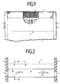
- the dry shaving apparatus shown in detail in FIG. 1 has a housing 1 on which a removable shaving head frame 2 is placed; Keys 3 are used to lock and unlock them.
- a shaving foil 4 is clamped arched in the shaving head frame 2 against which a lower knife 5 is pressed by a spring 6.
- the lower knife 5 is set in a back and forth working movement by a motor, not shown, housed in the housing 1 via a rocker arm 7.
- openings 9 are made for the passage of the buttons 3.
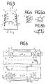
- bolts 12 with a rectangular cross section are provided, each of which has a dovetail-shaped guide 13 on their mutually facing longitudinal sides.
- a rib 14 is formed on each of these inner surfaces 10, namely adjacent to one of the two bolts 12, in such a way that the ribs 14 of the two inner surfaces 10 lie diagonally opposite one another.
- a strip 16 made of limited elastic material is fastened parallel to the clamping edge of the shaving foil 4, namely by means of three heads 17 molded onto the strip 16, through a central round hole 18 and two elongated holes 19 protrude in the shaving foil 4 and are welded to it.
- the two strips 16 of the shaving foil 4 are provided at the points corresponding to the bolts 12 of the shaving head frame 2 with mounting elements, which each strip 16 consist of two cutouts 21 which are open towards the perforated field 20 of the shaving foil 4, in each of which one of the bases 22 of the Cutout 21 is formed in the direction of the opening of the ascending hook 23 which, due to its inherent elasticity, can be pivoted in the plane of the strip 16.
- the angled ends 24 of the hooks 23 are chamfered and directed towards each bar 16 so that they can perform an opposite movement.
- one of the two cutouts 21 is also basically open to the perforated field 20 widespread slot 25 attached, which is adapted in its arrangement and its dimensions to the corresponding dimensions of the associated rib 14.
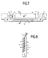
- the long sides 26 of the cutout 21 facing the angled ends 24 of the hooks 23 are chamfered at their edge (FIG. 7) and are dimensioned to match the guide 13 of the associated bolt 12, which then is inserted in the space between the hooks 23 and 4 when the shaving foil 4 is inserted the above-mentioned longitudinal side 26 of the cutout 21 comes to rest, as shown in FIG. 7.
- Grip ribs 27 are also formed on the inside of the strip 16 shown in FIG. 7.
- the shaving foil 4 is cut out at this point so that the grip ribs 27 can be reached from inside the shaving head frame 2 when the shaving foil 4 is installed.
- the thickness of the two longitudinal walls 11 of the shaving head frame 2 is divided into two sections 28 and 29, the thinner section 28 being intended for receiving the associated strip 16 (FIG. 8).
- the dimensions are chosen so that the sum of the thickness dimensions of the thinner section 28 and the associated strip 16 corresponds to the thickness of the other section 29. In this way, the interior of the shaving head frame 2 remains largely free of fissures, it can be kept relatively narrow and is easy to clean.
- each bolt 12 comes in front of the opening of the associated cutout 21 of the strip 16, pivots the hook 23 over its tapered end 24 to the side in the open position and continues to slide until the bottom 22 of the cutout 21 is reached and the hook 23 has returned to its initial closed position.
- the slanted longitudinal sides 26 of the two cutouts 21 of each strip 16 slide into the dovetail-shaped guides 13 of the two bolts 12 during this sliding movement.
- the shaving foil 4 is thus secured both against falling out of the holder in the sliding direction and against lifting off from the longitudinal wall 11 of the shaving head frame 2.
- the rib 14 also slides into the slot 25 of the bar 16 in question and thus secures the shaving foil 4 against being carried along by the pressed-on lower knife 5 in the direction of its working movements.
- Each bolt 12 is measured in its holder described above, a certain height play, which is determined by a defined distance a at the end 24 of the hook 23, so that the shaving foil 4 under the pressure acting on it during shaving together with the lower knife 5 against the Can dive inside the shaving head frame 2; the special design of the slot 25 with the extension at its base additionally ensures a one-sided immersion or tilting of the shaving foil 4.
- the hooks 23 perform the above-mentioned pivoting movement in reverse order. Damage to the shaving foil 4 is thus reliably avoided both when inserting and when removing.
Landscapes
- Engineering & Computer Science (AREA)
- Life Sciences & Earth Sciences (AREA)
- Forests & Forestry (AREA)
- Mechanical Engineering (AREA)
- Manufacturing & Machinery (AREA)
- Dry Shavers And Clippers (AREA)
- Manufacture Of Macromolecular Shaped Articles (AREA)
Applications Claiming Priority (3)
| Application Number | Priority Date | Filing Date | Title |
|---|---|---|---|
| DE4215398 | 1992-05-11 | ||
| DE4215398A DE4215398C1 (enExample) | 1992-05-11 | 1992-05-11 | |
| PCT/EP1993/000987 WO1993023213A1 (de) | 1992-05-11 | 1993-04-23 | Scherfolienhalterung für einen trockenrasierapparat |
Publications (2)
| Publication Number | Publication Date |
|---|---|
| EP0640025A1 EP0640025A1 (de) | 1995-03-01 |
| EP0640025B1 true EP0640025B1 (de) | 1995-12-06 |
Family
ID=6458545
Family Applications (1)
| Application Number | Title | Priority Date | Filing Date |
|---|---|---|---|
| EP93911499A Expired - Lifetime EP0640025B1 (de) | 1992-05-11 | 1993-04-23 | Scherfolienhalterung für einen trockenrasierapparat |
Country Status (6)
| Country | Link |
|---|---|
| US (1) | US5553383A (enExample) |
| EP (1) | EP0640025B1 (enExample) |
| JP (1) | JPH07506992A (enExample) |
| AT (1) | ATE131098T1 (enExample) |
| DE (2) | DE4215398C1 (enExample) |
| WO (1) | WO1993023213A1 (enExample) |
Families Citing this family (4)
| Publication number | Priority date | Publication date | Assignee | Title |
|---|---|---|---|---|
| DE19632333C1 (de) * | 1996-08-10 | 1997-06-05 | Braun Ag | Trockenrasierapparat |
| US20060143924A1 (en) * | 2004-12-30 | 2006-07-06 | Rovcal, Inc. | Electric shaver |
| US20070022606A1 (en) * | 2005-07-29 | 2007-02-01 | Mcguire Kenneth S | Shaving foil |
| US7845079B2 (en) * | 2005-07-29 | 2010-12-07 | The Gillette Company | Shaving foil |
Family Cites Families (7)
| Publication number | Priority date | Publication date | Assignee | Title |
|---|---|---|---|---|
| US2360679A (en) * | 1939-11-13 | 1944-10-17 | Fred E Sudlow | Razor |
| BE635381A (enExample) * | 1962-07-24 | 1900-01-01 | ||
| CH467136A (de) * | 1967-10-19 | 1969-01-15 | Apag App Bau Ag | Trockenrasierapparat |
| DE2019746C3 (de) * | 1970-04-23 | 1978-07-13 | Braun Ag, 6000 Frankfurt | Scherfolienhalterung für einen Trockenrasierapparat |
| JPS582708B2 (ja) * | 1976-10-27 | 1983-01-18 | 日立マクセル株式会社 | 電気かみそりの外刃補強板止着ピンの製造法 |
| DE3302610C2 (de) * | 1983-01-27 | 1986-03-27 | Braun Ag, 6000 Frankfurt | Scherkopf für Trockenrasierapparate |
| DE3833179A1 (de) * | 1988-09-30 | 1990-04-05 | Braun Ag | Scherkopf fuer trockenrasierapparate |
-
1992
- 1992-05-11 DE DE4215398A patent/DE4215398C1/de not_active Expired - Fee Related
-
1993
- 1993-04-23 EP EP93911499A patent/EP0640025B1/de not_active Expired - Lifetime
- 1993-04-23 JP JP5519811A patent/JPH07506992A/ja active Pending
- 1993-04-23 WO PCT/EP1993/000987 patent/WO1993023213A1/de not_active Ceased
- 1993-04-23 AT AT93911499T patent/ATE131098T1/de active
- 1993-04-23 DE DE59301119T patent/DE59301119D1/de not_active Expired - Fee Related
- 1993-04-23 US US08/335,790 patent/US5553383A/en not_active Expired - Fee Related
Also Published As
| Publication number | Publication date |
|---|---|
| EP0640025A1 (de) | 1995-03-01 |
| US5553383A (en) | 1996-09-10 |
| JPH07506992A (ja) | 1995-08-03 |
| ATE131098T1 (de) | 1995-12-15 |
| WO1993023213A1 (de) | 1993-11-25 |
| DE59301119D1 (de) | 1996-01-18 |
| DE4215398C1 (enExample) | 1992-12-10 |
Similar Documents
| Publication | Publication Date | Title |
|---|---|---|
| DE69906882T2 (de) | Motorsäge mit Sägeblattspeichervorrichtung | |
| EP0857363B1 (de) | Gerätestecker für elektrogeräte | |
| EP1056628B1 (de) | Vorrichtung zum gelenkigen verbinden eines wischblatts für scheiben von kraftfahrzeugen mit einem wischerarm und verfahren zum herstellen dieser verbindung | |
| EP1464247B1 (de) | Reinigungsvorrichtung für einen Rasierapparat | |
| DE3727921C1 (de) | Schalter zur Ein- und Ausschaltung eines elektrisch betreibbaren Antriebsteiles eines Geraetes | |
| DE8128811U1 (de) | Rasierklingenspender | |
| DE102005016486A1 (de) | Vorrichtung zum gelenkigen Verbinden eines Wischblatts mit einem Wischarm eines Scheibenwischers | |
| DE2609909A1 (de) | Einrichtung zum reinigen von rasierklingen in tandemanordnung | |
| DE2429539A1 (de) | Elektrischer rasierapparat | |
| DE7625463U1 (de) | Klingenblock fuer einen rasierapparat | |
| DE813667C (de) | Schergeraet fuer Rasierschnitt | |
| EP0640025B1 (de) | Scherfolienhalterung für einen trockenrasierapparat | |
| DE3804812A1 (de) | Trockenrasierer mit auswechselbarem scherkopf | |
| DE2816929C2 (de) | Vorrichtung zum Zerkleinern von Nahrungsmitteln | |
| EP0263430B1 (de) | Sonnendach | |
| DE1553812B2 (de) | Scherkopf für einen Trockenrasierapparat | |
| DE4222758A1 (de) | Seil- oder kabel/schlauch-fuehrungskette | |
| DE1183405B (de) | Trockenrasiergeraet | |
| EP0262741B1 (de) | Scherkopf für einen Trockenrasierapparat. | |
| DE2447087A1 (de) | Rasierklingeneinheit | |
| DE1152917B (de) | Elektrischer Trockenrasierapparat | |
| DE2636534C2 (de) | Klingenblock für einen Rasierapparat | |
| DE19824176C2 (de) | Elektrischer Rasierapparat | |
| DE2834474B2 (de) | Vorrichtung zum Lagern von Instrumenten | |
| DE102018004626A1 (de) | Wischarm für eine Scheibenwischanlage eines Kraftfahrzeugs |
Legal Events
| Date | Code | Title | Description |
|---|---|---|---|
| PUAI | Public reference made under article 153(3) epc to a published international application that has entered the european phase |
Free format text: ORIGINAL CODE: 0009012 |
|
| 17P | Request for examination filed |
Effective date: 19941109 |
|
| AK | Designated contracting states |
Kind code of ref document: A1 Designated state(s): AT CH DE FR GB IT LI NL |
|
| 17Q | First examination report despatched |
Effective date: 19950509 |
|
| ITF | It: translation for a ep patent filed | ||
| GRAA | (expected) grant |
Free format text: ORIGINAL CODE: 0009210 |
|
| RAP1 | Party data changed (applicant data changed or rights of an application transferred) |
Owner name: BRAUN AKTIENGESELLSCHAFT |
|
| AK | Designated contracting states |
Kind code of ref document: B1 Designated state(s): AT CH DE FR GB IT LI NL |
|
| REF | Corresponds to: |
Ref document number: 131098 Country of ref document: AT Date of ref document: 19951215 Kind code of ref document: T |
|
| GBT | Gb: translation of ep patent filed (gb section 77(6)(a)/1977) |
Effective date: 19951207 |
|
| REF | Corresponds to: |
Ref document number: 59301119 Country of ref document: DE Date of ref document: 19960118 |
|
| REG | Reference to a national code |
Ref country code: CH Ref legal event code: NV Representative=s name: PATENTANWALTSBUREAU BOSSHARD UND LUCHS |
|
| ET | Fr: translation filed | ||
| PLBE | No opposition filed within time limit |
Free format text: ORIGINAL CODE: 0009261 |
|
| STAA | Information on the status of an ep patent application or granted ep patent |
Free format text: STATUS: NO OPPOSITION FILED WITHIN TIME LIMIT |
|
| 26N | No opposition filed | ||
| PGFP | Annual fee paid to national office [announced via postgrant information from national office to epo] |
Ref country code: DE Payment date: 19970312 Year of fee payment: 5 |
|
| PGFP | Annual fee paid to national office [announced via postgrant information from national office to epo] |
Ref country code: GB Payment date: 19970317 Year of fee payment: 5 |
|
| PGFP | Annual fee paid to national office [announced via postgrant information from national office to epo] |
Ref country code: AT Payment date: 19970320 Year of fee payment: 5 |
|
| PGFP | Annual fee paid to national office [announced via postgrant information from national office to epo] |
Ref country code: FR Payment date: 19970416 Year of fee payment: 5 |
|
| PGFP | Annual fee paid to national office [announced via postgrant information from national office to epo] |
Ref country code: NL Payment date: 19970428 Year of fee payment: 5 |
|
| PGFP | Annual fee paid to national office [announced via postgrant information from national office to epo] |
Ref country code: CH Payment date: 19970605 Year of fee payment: 5 |
|
| PG25 | Lapsed in a contracting state [announced via postgrant information from national office to epo] |
Ref country code: GB Free format text: LAPSE BECAUSE OF NON-PAYMENT OF DUE FEES Effective date: 19980423 Ref country code: AT Free format text: LAPSE BECAUSE OF NON-PAYMENT OF DUE FEES Effective date: 19980423 |
|
| PG25 | Lapsed in a contracting state [announced via postgrant information from national office to epo] |
Ref country code: LI Free format text: LAPSE BECAUSE OF NON-PAYMENT OF DUE FEES Effective date: 19980430 Ref country code: FR Free format text: THE PATENT HAS BEEN ANNULLED BY A DECISION OF A NATIONAL AUTHORITY Effective date: 19980430 Ref country code: CH Free format text: LAPSE BECAUSE OF NON-PAYMENT OF DUE FEES Effective date: 19980430 |
|
| PG25 | Lapsed in a contracting state [announced via postgrant information from national office to epo] |
Ref country code: NL Free format text: LAPSE BECAUSE OF NON-PAYMENT OF DUE FEES Effective date: 19981101 |
|
| REG | Reference to a national code |
Ref country code: CH Ref legal event code: PL |
|
| GBPC | Gb: european patent ceased through non-payment of renewal fee |
Effective date: 19980423 |
|
| NLV4 | Nl: lapsed or anulled due to non-payment of the annual fee |
Effective date: 19981101 |
|
| PG25 | Lapsed in a contracting state [announced via postgrant information from national office to epo] |
Ref country code: DE Free format text: LAPSE BECAUSE OF NON-PAYMENT OF DUE FEES Effective date: 19990202 |
|
| REG | Reference to a national code |
Ref country code: FR Ref legal event code: ST |
|
| PG25 | Lapsed in a contracting state [announced via postgrant information from national office to epo] |
Ref country code: IT Free format text: LAPSE BECAUSE OF NON-PAYMENT OF DUE FEES;WARNING: LAPSES OF ITALIAN PATENTS WITH EFFECTIVE DATE BEFORE 2007 MAY HAVE OCCURRED AT ANY TIME BEFORE 2007. THE CORRECT EFFECTIVE DATE MAY BE DIFFERENT FROM THE ONE RECORDED. Effective date: 20050423 |