EP0636537B1 - Système de transmission de puissance - Google Patents
Système de transmission de puissance Download PDFInfo
- Publication number
- EP0636537B1 EP0636537B1 EP94111665A EP94111665A EP0636537B1 EP 0636537 B1 EP0636537 B1 EP 0636537B1 EP 94111665 A EP94111665 A EP 94111665A EP 94111665 A EP94111665 A EP 94111665A EP 0636537 B1 EP0636537 B1 EP 0636537B1
- Authority
- EP
- European Patent Office
- Prior art keywords
- transmission system
- power transmission
- planetary
- motor
- crankshaft
- Prior art date
- Legal status (The legal status is an assumption and is not a legal conclusion. Google has not performed a legal analysis and makes no representation as to the accuracy of the status listed.)
- Expired - Lifetime
Links
Images


Classifications
-
- B—PERFORMING OPERATIONS; TRANSPORTING
- B62—LAND VEHICLES FOR TRAVELLING OTHERWISE THAN ON RAILS
- B62M—RIDER PROPULSION OF WHEELED VEHICLES OR SLEDGES; POWERED PROPULSION OF SLEDGES OR SINGLE-TRACK CYCLES; TRANSMISSIONS SPECIALLY ADAPTED FOR SUCH VEHICLES
- B62M6/00—Rider propulsion of wheeled vehicles with additional source of power, e.g. combustion engine or electric motor
- B62M6/40—Rider propelled cycles with auxiliary electric motor
- B62M6/45—Control or actuating devices therefor
-
- B—PERFORMING OPERATIONS; TRANSPORTING
- B62—LAND VEHICLES FOR TRAVELLING OTHERWISE THAN ON RAILS
- B62M—RIDER PROPULSION OF WHEELED VEHICLES OR SLEDGES; POWERED PROPULSION OF SLEDGES OR SINGLE-TRACK CYCLES; TRANSMISSIONS SPECIALLY ADAPTED FOR SUCH VEHICLES
- B62M11/00—Transmissions characterised by the use of interengaging toothed wheels or frictionally-engaging wheels
- B62M11/04—Transmissions characterised by the use of interengaging toothed wheels or frictionally-engaging wheels of changeable ratio
- B62M11/14—Transmissions characterised by the use of interengaging toothed wheels or frictionally-engaging wheels of changeable ratio with planetary gears
-
- B—PERFORMING OPERATIONS; TRANSPORTING
- B62—LAND VEHICLES FOR TRAVELLING OTHERWISE THAN ON RAILS
- B62M—RIDER PROPULSION OF WHEELED VEHICLES OR SLEDGES; POWERED PROPULSION OF SLEDGES OR SINGLE-TRACK CYCLES; TRANSMISSIONS SPECIALLY ADAPTED FOR SUCH VEHICLES
- B62M6/00—Rider propulsion of wheeled vehicles with additional source of power, e.g. combustion engine or electric motor
- B62M6/40—Rider propelled cycles with auxiliary electric motor
- B62M6/55—Rider propelled cycles with auxiliary electric motor power-driven at crank shafts parts
-
- F—MECHANICAL ENGINEERING; LIGHTING; HEATING; WEAPONS; BLASTING
- F16—ENGINEERING ELEMENTS AND UNITS; GENERAL MEASURES FOR PRODUCING AND MAINTAINING EFFECTIVE FUNCTIONING OF MACHINES OR INSTALLATIONS; THERMAL INSULATION IN GENERAL
- F16H—GEARING
- F16H37/00—Combinations of mechanical gearings, not provided for in groups F16H1/00 - F16H35/00
- F16H37/02—Combinations of mechanical gearings, not provided for in groups F16H1/00 - F16H35/00 comprising essentially only toothed or friction gearings
- F16H37/021—Combinations of mechanical gearings, not provided for in groups F16H1/00 - F16H35/00 comprising essentially only toothed or friction gearings toothed gearing combined with continuous variable friction gearing
Definitions
- the present invention relates to a power transmission system, specifically for an electrically power assisted vehicle such as a bicycle, comprising a rotary motor output shaft of an electrical motor, a planetary type transmission disposed coaxially to said output shaft drivingly connected thereto and a driven component drivingly connected with said planetary type transmission.
- Said power transmission system is known from CH-A-593 822, however, shows the following problems.
- Figure 12 shows a motor 101, a planetary gear type transmission 102 (hereinafter only called transmission) and a driven device 103 connected to an axial end portion of the transmission 102.
- a projection 105 for fitting into a fitting recess 104 provided on the transmission 102 is formed on an axial end portion of the motor 101.
- the axial end portion of the transmission 102 is also formed with a fitting projection 107 for fitting into a fitting recess 106 on the driven device 103.
- output gears 108, 109 intermesh with mating gears (not shown) in axially aligned state by fitting the projections 105, 107 and the recesses 104, 103 to each other.
- such a connecting structure has been applied to electrical motor power assisted bicycles which are operated by a resultant force of a rider's pedal force and the driving force of the electric motor having a planetary gear type transmission interposed between the electrical motor and the driven components of the bicycle such as shown in European patent applications 0517224, 0569954, 0590674 or 0559231.
- the afore-indicated attachment structure for connecting an electrical motor, a planetary gear type transmission and a driven device to each other is disadvantageous in that in such cases the fear of a misalignment of the components is relatively large because there are two spots of fitting, namely between the motor 101 and the transmission 102 and between the transmission 102 and the driven component 103.
- an attachment error in terms of misalignment is relatively large, noise is likely to be produced additionally from the meshing areas of the output gears 108, 109 and the lifetime of said machine components is shortened.
- the above objective is solved for a power transmission system as indicated above in that the planetary type transmission comprises a planetary roller type transmission having an outer ring being affixed nonrotatably leaving a space between the outer ring and the motor output shaft to accommodate a plurality of planetary elements frictionally engaged with the motor output shaft and the outer ring, respectively, said frictional planetary elements being rotatably supported by a carrier drivingly connected to said driven component.
- the planetary type transmission comprises a planetary roller type transmission having an outer ring being affixed nonrotatably leaving a space between the outer ring and the motor output shaft to accommodate a plurality of planetary elements frictionally engaged with the motor output shaft and the outer ring, respectively, said frictional planetary elements being rotatably supported by a carrier drivingly connected to said driven component.
- a further aspect of the present invention is to provide said power transmission system having an improved one-way clutch between a driving and driven member which provides a self-centering function and which can easily be assembled without steel balls or rollers therein reducing the size and weight of the clutch as well.
- the one-way clutch usable in the power transmission system comprises cylindrical inner and outer members which are coaxially disposed with an annular space left in between wherein a plurality of circumferencially spaced pawls are disposed and pivotably supported by the one of said inner and outer members to be prebiased into one-way engagement with engagement teeth provided along the complete facing opposite cylindrical surface of the other member, said pawl-supporting member moreover comprises at least one, preferrably a plurality of spaced self-centering slide contact projections which extend in the circumferencial direction of the member and which are in sliding contact with the engagement teeth of the other member to align the axis of the two members.
- a power transmission system according to the present invention is explained in conjunction with an electrical motor assisted bicycle to which the power transmission system according to the present invention is applied to transmit assisting motor power to a driven component such as a rear wheel of the vehicle in addition to a human power transmission provided from a pedal-operated crankshaft.
- Figures 1 and 2 show a motor-operated bicycle (1) and a frame (2) of the motor-operated bicycle (1).
- the frame (2) comprises a head pipe (2a) supporting a front fork (4) for free steering with the front fork (4) supporting a front wheel (3) for free rotation, a down tube (2b) extending from the head pipe (2a) back downward, a seat tube (2c) connected through a middle lug (5) to the rear part of the down tube (2b), a pair of right and left chain stays (2d) connected through the a hanger lug (6) to the rear part of the down tube (2b), and a pair of right and left seat stays (2e) connecting the upper part of the seat tube (2c) to the rear end parts of the chain stays (2d).
- a pair of handlebars (7) is is attached to the upper end part of the front fork (4).
- the rear end parts of the chain stay (2d) and the seat stay (2e) are joined to be integral with a rear wheel bracket (2f) on either side of a rear wheel (8) to support the rear wheel (8) for free rotation.
- the assist power unit (9) of the motor-operated bicycle (1) is provided with a new type of one-way clutch 28 as explained hereinafter.
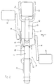
- the assist power unit (9) comprises; a motor (12) receiving electric power from a battery (11) accommodated in a battery case (10) and controlled by a control unit which will be described later, a power unit (14) having a crankshaft (13), a crank gear (15) provided on the right hand side of the crankshaft (13) as shown in FIG. 4, a crank (16), and a pedal (17). (0020)
- the power unit (14) is centered on the crankshaft (13).
- the motor (12) is located along and below the down tube (2b) and in front of the crankshaft (13), and connected through connection brackets (18, 19) to the middle lug (5) and to the hanger lug (6).
- the assist power unit (9) is mounted on the frame (2) so that a rotary shaft (12a) to be described later of the motor (12) is parallel to the down tube (2b).
- a crank gear (15) located on the right hand side of the assist power unit (9) is connected through a chain (20) to a freewheel (not shown) of the rear wheel (8).
- the freewheel is constituted with a known one-way clutch for transmitting power from the chain (20) only to the rear wheel (8).
- a chain cover (20a) is shown to enclose the chain (20).
- a control unit (21) and a main switch (22) both mounted on the down tube (2b) are connected to the motor (12) of the assist power unit (9).
- the control unit (21) is constituted to rotate the motor (12) to transmit power of the motor (12) to the crankshaft (13) only when the main switch (22) is set to on and a rider exerts a pedal force on the crank shaft (13).
- the crankshaft receives a torque from the motor (12) in addition to the pedal force.
- the output of the motor (12) is controlled by the control unit (21) so as to be generally proportional to the pedal force exerted on the pedal (17).
- the pedal force is detected by a pedal force detection mechanism of the power unit (14) which will be described later.
- control unit (21) and the main switch (22) are below the down tube (2b) and forward of the motor (12). Therefore, the main switch (22), control unit (21), motor (12), and power unit (14) are arranged in a row along the down tube (2b) from front to rear.
- the main switch (22) is constituted such that, when a key (not shown) is inserted and turned clockwise from the neutral position for example in FIG. 1, the control unit (21) is electrically connected to the battery (11), and when turned counterclockwise, a locking device for a battery case is released, which will be described later.
- the crankshaft (13) is supported for free rotation by a case (23) of the power unit (14).
- the motor (12) is secured to one end of the case (23) so that the motor axis is at right angles to the crankshaft (13).
- all the rotating parts arranged coaxially with the crankshaft (13) are made smaller in diameter than the crank gear (15) to secure a sufficient ground clearance by reducing their sizes.
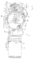
- the case (23), as shown in FIG. 4, comprises a case body (23a) and a lid member (23d).
- the crankshaft (13) passes through the case body (23a) in which the planetary gear type step-up transmission (24) is housed.
- the lid member (23d) is secured by screws to a left hand side, larger diameter one of openings on both ends of the cylindrical portion to close the opening while supporting the left end of the crankshaft for free rotation by means of a bearing (23c).
- a cover (26) of a generally circular shape is secured to the outside of the lid member (23d).
- the planetary gear type step-up transmission (24) comprises planetary gears (27) supported by the crankshaft (13) through a one-way clutch (28) constituted according to the present invention, a sun gear (29) supported for free rotation by the crankshaft (13), and an outer circumferential gear (30) extending cylindrically outward in the vehicle width direction and secured by rivets to a cylindrical output shaft (31).
- the outer circumference of the outer circumferential gear (30) is formed with a smaller diameter on the cylindrical output shaft (31) side than on the side where the planetary gears (27) engage to prevent the size of the planetary gear type step-up transmission (24) from increasing excessively.
- the one-way clutch (28) is constituted so that power is transmitted from the crankshaft (13) to the planetary gear type step-up transmission (24) only when the crankshaft (13) rotates counterclockwise as seen in FIG. 3 relative to the the planetary gear type step-up transmission (24).
- the one-way clutch 28 is shown in most detail in Figure 7, and in addition to acting as a one-way clutch, it provides a bearing arrangement for ensuring a coaxial relationship of the various elements of the one-way clutch and thus avoids the necessity of separate bearing elements to maintain the inner and outer races of the one-way clutch in their relationship.
- FIG. 13 and 14 Such a prior art type of one-way clutch and bearing assembly is shown in Figures 13 and 14 wherein there is provided a driving connection between an inner hub 211 and an outer member such as a sprocket 212.
- the inner hub 211 has affixed for rotation with it an inner member 213 that pivotally supports a plurality of pawls 214 in pockets 215.
- pawls 214 are normally biased outwardly by spring arrangement into receptive recesses 216 formed integrally within the interior of the sprocket 212 so as to establish a driving relationship in the counterclockwise direction as seen in Figure 2 but to permit the sprocket 212 to overrun the hub 211 under some conditions.
- Ball bearings 217 are interposed in races formed between the hub 211 and a threaded end piece 218 and in the sprocket 212. As a result, it is necessary to provide a complicated assembly arrangement for maintaining the desired relative rotational axes between the hub 211 and sprocket 212 which adds significantly to the cost and complexity of the assembly.
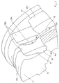
- the one-way clutch (28), as shown in FIGs. 7 and 9, comprises an inner ring (32) of a generally annular shape and secured to the crankshaft (13) by means of splines, an outer ring (34) formed with a hollow portion to accommodate the inner ring (32) and with engagement teeth (33) of saw tooth-like cross section over the entire inner circumference, pawls (35) interposed between the inner ring (32) and the outer ring (34), and a spring (36) urging the pawls (35) to engage with the engagement teeth (33).
- the outer ring (34) is provided with pivot shafts (27a) for supporting the planetary gears (27) for free rotation and serving also as carrier.
- the outer circumference of the inner ring (32) is provided with four projections (37) as slide contact projections projecting radially outward and equally spaced over the outer circumference.
- Pawl supporting recesses (38) of a concave arcuate cross section are formed on the outer circumference of the inner ring (32) at locations among the projections (37).
- Each projection (37) has a projection end surface (37a) which is an arcuate surface about the center of the inner ring (32).
- the pawl (35) is made up of a base portion (35a) of an arcuate cross section for freely slidable fit into the recess (38) in the inner ring (32) and of an engagement portion (35b) extending forward, in the rotating direction of the inner ring (32) (counterclockwise in FIG. 7) during power transmission, from the base portion (35a) for the extended end of the pawl to engage with the engagement teeth (33).
- the engagement tooth (33) has a gentle slope from the apex forward in the rotating direction, during power transmission, of the inner ring (32) and a steep slope on the opposite side.
- the pawl (35) is formed with a cut (35c) extending from its extended end toward the base portion (35a) for receiving the spring (36). The bottom of the cut (35c) is formed flat and sloped in the extending direction of the engagement portion (35b) as shown in FIG. 7.
- the slope angle of the bottom surface is set under the state shown in FIG. 7, showing the base portion (35a) fit in the recess (38) and the engagement portion (35b) engaging with the engagement tooth (33), so that the rear end portion of the bottom surface opposite to the rotating direction of the inner ring (32) during power transmission projects radially more outward than the forward portion.
- the spring (36) is in contact with the projecting end of the bottom surface.
- the spring (36) is formed in an annular shape with a part of it cut open and installed in the inner ring (32) in radially expanded state.
- the outer ring (34) is axially aligned with the inner ring (32) by the contact of all the projections (37) of the inner ring (32) with the apexes of the engagement teeth (33) and is supported for free rotation by the inner ring (32) without using steel balls or the like.
- the power (or the pedal force produced when the pedal (17) is depressed) is transmitted from the inner ring (32) to the outer ring (34) only when the crankshaft (13) and the inner ring is rotated counterclockwise relative to the outer ring (34) as seen in FIG. 7.
- the one-way clutch (28) does not transmit power as when the crank (16) is pedalled backward, or the outer ring (34) rotates counterclockwise faster than the inner ring (32).
- the power of the crankshaft (13) is transmitted through the chain (20) and the freewheel to the rear wheel (8) by the rotation of the cylindrical output shaft (31) to which the outer circumferential gear (30) is riveted and by the rotation of the crank gear (15) secured to the axial end of the cylindrical output shaft (31). As shown in FIG.
- a ring gear (40) to which power is transmitted from the planetary roller type transmission (25) which will be described later is riveted, together with the outer circumferential gear (30), to the cylindrical output shaft (31) supported for free rotation through a bearing (41) by the case body (23a).
- the end portion of the crankshaft (13) on the right hand side of the vehicle is supported for free rotation through a bearing (42) in the hollow portion of the cylindrical output shaft (31).
- this embodiment employs as shown in FIG. 3 a stopper (43) and a pedal force detection mechanism (44).
- the stopper (43) is screwed into the case body (23a) so that its fore-end comes in contact with the lower end surface of the arm (29a) of the sun gear (29).
- the pedal force detection mechanism (44) comprises a potentiometer device (46) coming from above into contact with a contact plate (45) riveted to the projecting end of the arm (29), and a pressing device (47) for urging the potentiometer device (46) toward the contact plate (45).
- the contact plate (45) is made wide enough to reduce surface pressure.
- the potentiometer (46) of the pedal force detection mechanism (44) comprises a lever (46a) having a swinging end for coming into contact with the contact plate (45), and a potentiometer proper (46b) connected to the lever (46a), and is fixedly supported by the case body (23a).
- the potentiometer proper (46b) is arranged for free rotation about an input shaft (46c) with its axis perpendicular to the drawing surface of FIG. 3 and connected to the lever (46a). Rotation angle of the input shaft (46c) is detected and the detected signal is sent through a lead (46d) to the control unit (21).
- the input shaft (46c) is supported for free rotation by the case body (23a).
- the pressure device (47) comprises a pressing element (47a) for coming into contact with the swinging end of the lever (46a), a case (47b) secured to the case body (23a) and supporting the pressing element (47a) for free movement to and away from the lever (46a), and a compression coil spring (47c) for urging the pressing element (47a) toward the lever (46a).
- the potentiometer proper (46b) detects the amount of rotation and outputs the detected signal to the control unit (21).
- the control unit (21) controls the motor (12) according to the detected signal from the potentiometer proper (46b).
- the motor (12) is controlled so that its revolution is in proportion to the amount of rotation of the sun gear (29).
- the revolution of the outer circumferential gear (30) is detected by a revolution sensor (48) shown in FIG. 3. From the revolution of the outer circumferential gear (30) and the amount of rotation of the sun gear (29) detected by the potentiometer proper (46b), a motor drive force is calculated as shown in FIG. 9 by the control unit (21) to drive the motor (12).
- the motor (12) is controlled to produce a torque generally proportional to the pedal force produced by depressing the pedal (17).
- the revolution sensor (48) is of a known type screwed into the case body (23a). The screwed in end of the sensor (48) opposes with a minute gap to the left hand side end of the outer circumferential gear (30) to detect the revolution by utilizing changes in the magnetic resistance caused by a large number of teeth (30a) formed on the outer circumferential gear (30).
- the use of the teeth (30a) formed on the outer circumferential gear (30) for detecting the revolution in this way eliminates the need for a special component for detecting the revolution when detecting the revolution by means of the revolution sensor (48).
- a rotary shaft (12a) of the motor (12) is connected to the cylindrical output shaft (31) through the planetary roller type transmission (25), a one-way clutch (51) on the motor side, an output gear member (52) and the ring gear (40) engaging with the output gear member (52).
- a collar (52a) is press-fit into the output gear member (52).
- the planetary roller type transmission (25) comprises an outer ring (53) formed in the shape of a cylinder having a diameter greater than that of the rotary shaft (12a) of the motor (12) and secured to the end portion of the shaft of the motor (12) coaxially with the rotary shaft, a plurality of planetary rollers (54) arranged between and contacted by the outer ring (53) and the rotary shaft (12a), and an carrier (56) having pins (55) respectively supporting the planetary rollers (54) for free rotation and transmitting power to the output gear member (52) through the one-way clutch (51) located on the motor side.
- Guide plates (57, 58) are arranged on both axial side ends of the outer ring (53) to prevent the planetary rollers (54) from moving in the axial directions.
- the outer ring (53) is secured to the motor (12) by means of securing bolts (59).
- the through holes in the outer ring (53) and the guide plates (57, 58) for passing the securing bolt (59) are formed with a diameter greater than the diameter of the bolts (59) so that the positions of those components are not restricted radially by the bolts (59).
- a circular fitting portion (60) of the case body (23a) fits over the outer circumference of the outer ring (53). Namely the outer circumferential surface of the outer ring (53) constitutes a fitting surface.
- the motor (12) is connected to the case body (23a) in the state of the outer ring (53) being fit into the circular fitting portion (60) by means of connection bolts (61).
- each roller (54) is supported for free rotation by a bearing (62) and a pin (55) press fit into the carrier (56).
- the carrier (56) is formed in a bottomed cylindrical shape with the pin (55) studded to project, and its hollow space accommodates the one-way clutch (51) located on the motor side and the output gear member (52).
- each of the planetary rollers (54) rotates in the direction opposite to the rotating direction of the rotary shaft (12a) and rolls over the inner surface of the outer ring (53) so as to revolve clockwise.
- the carrier(56) rotates clockwise as seen in FIG. 8 at a specified speed reduction ratio.
- the output gear member (52) is supported by a bearing (63) in the case body (23a) so that its movement in the axial direction is restricted. Its axial end on the motor side is connected to the motor side one-way clutch (51) while the opposite end is formed as a bevel gear meshing with the ring gear (40).
- the reason for interposing the motor side one-way clutch (51) in the power transmission train of the motor (12) in this way is to prevent drive resistance from being increased by the transmission of power from the crankshaft (13) through the ring gear (40), the output gear member (52), and the planetary roller type transmission (25) to the motor (12), as when revolution of the motor (12) slows down as a result of decrease in the power of the battery (11), or when the motor power is intentionally turned off to drive by the human power only.
- balls (64, 65) are installed respectively in circular recesses formed at the ends of the rotary shaft (12a) and the output gear member (52) so as to be located between the rotary shaft (12a) and the bottom surface of the carrier (56) and between the inner bottom surface of the carrier (56) and the output gear member (52) for preventing the carrier (56) from coming into contact with the rotary shaft (12a) or with the output gear member (52) when an axial thrust is applied to the carrier (56).
- the rotary shaft (12a) of the motor (12) is press fit among the planetary rollers (54) so that the planetary rollers (54) and the carrier (56) can rotate relative to the rotary shaft (12a).
- the ball (64) is placed to be held between the rotary shaft (12a) and the carrier (56). This causes the outer ring (53) and the carrier (56) to be axially lined up with the rotary shaft (12a).
- the outer ring (53) and the guide plates (57, 58) are secured by bolts (59) to the motor (12).
- the planetary roller type transmission (25) is attached to the motor (12).
- diameter of the through holes in the outer ring (53) and the guide plates (57, 58) through which the bolts are passed are made larger than the diameter of the bolt so that the positions of the outer ring (53) and the guide plates (57, 58) are not restricted by the bolts. Namely, no special fitting structure is required to connect the planetary roller type transmission (25) to the motor (12).
- the outer circumference surface of the outer ring (53) is fit in the circular fitting portion (60) of the case body (23a).
- the motor side one-way clutch (51) is inserted beforehand into the hollow space in the carrier (56) or fit over the output gear member (52) so that connection of the carrier (56) and the output gear member (52) is made at the motor side one-way clutch (51).
- the interior of the hollow space in the carrier (56) formed in a bottomed cylindrical shape serves as the axial connection portion relative to the output gear member (52) to be part of the driven device.
- the carrier (56) is connected to the output gear member (52) through the motor side one-way clutch (51), spatial room in the radial direction is produced corresponding to the displacement of a working piece (not shown) of the motor side one-way clutch (51), and connection of both components can be easily made.
- the carrier (56) is drawn out from the output gear member (52) on the other hand, the drawing is also made under the condition of radial spatial room.
- the ball (65) is also installed beforehand in the output gear member (52).
- bolt holes (66. 67) drilled in the case body (23a) are lined up with the bolt holes in the brackets (18, 19) and the case body (23a) is secured to the brackets (18, 19) by means of bolts.
- the battery case (10) is formed as shown in FIGs. 1 and 8 in a box shape elongate in up and down directions, accommodating two batteries (11), and placed between the seat tube (2c) and the rear wheel (8).
- the dimensions of the battery case (10) are set, as seen in FIG. 2, so that the dimension in the vehicle width direction is within the space between two seat stays (2e) and the dimension in the fore-and-aft directions is within the space between the seat tube (2c) and a right and left pair of auxiliary seat tubes (71).
- the auxiliary seat tubes (71) extend generally parallel to the seat tube (2c) between the rear end of the down tube (2b) and a cross member bridging the right and left stays (2e).
- the battery case (10), the assist power unit (9), and the control unit (21) are all accommodated in the space between the right and left cranks (16, 16).
- a bottomed support box (72) opening upward is arranged near the rear end of the down tube (2b) in which the lower end of the battery case (10) is fit from above.
- the support box (72) is supported indirectly by the frame (2) with the lower front part of the support box (72) connected to a bracket (73) of the middle lug (5).
- the battery case (10) is mounted on the vehicle body so as to be detachable in the upward direction of the vehicle.
- a male connector (72a) is provided on the bottom of the support box (72) to be electrically connected to a female connector (10a) provided on the lower end of the battery case (10).
- a lock mechanism (74) is provided on the bottom of the support box (72) to prevent the battery case (10) from being removed from the vehicle body by an unauthorized person.
- the male connector (72a) is electrically connected through a main switch (22) to the control unit (21) and the motor (12).
- a contact piece projects into the support box (72). Namely, when the battery case (10) is fit from above into the support box (72), the female connector (10a) on the battery case (10) side is electrically connected to the female connector (72a) so that electrical connection is made from the battery (11) to the main switch (22) and other electric devices.
- the lock mechanism (74) is mounted for free rotation on the support box (72) and has an engagement pawl (74a) capable of freely engaging with and disengaging from the battery case (10) so that the battery case (10) is locked by fitting the battery case (10) into the support box (72).
- the pawl (74a) is connected through a wire (74b) to the main switch (22) so as to be disengaged when a key of the main switch (22) is turned to the lock releasing side (counterclockwise in FIG. 1).
- the saddle (75) is attached to the top end of a seat pillar tube (77) and attached to the frame (2) by inserting the seat pillar tube (77) into the seat tube (2c).
- the saddle (75) in the present embodiment is padded and sprung.
- the seat pillar tube (77) has a certain length so as to change the height of the saddle (75) according to the size of a rider, with a seat tilt mechanism (76) provided at its lower end.
- a seat pin (78) provided at the upper end of the seat tube (2c) to change the upper end opening diameter of the seat tube (2c) is loosened, the seat pillar tube (77) is pulled up from the seat tube (2c) by pulling up the saddle (75).
- the seat pin (78) is tightened to squeeze the seat pillar tube (77) by the upper opening of the seat tube (2c).
- the seat tilt mechanism (76) comprises an upper member (76a) inserted in and secured by the lower end of the seat pillar tube (77), and a lower member (76c) pivoted for free swing to the upper member (76a) through a pivot pin (76b) and inserted in the seat tube (2c).
- the pivot pin (76b) is attached with its axis directed in the vehicle width direction.
- the seat tilt mechanism (76) when the vehicle is driven, the seat tilt mechanism (76) is inserted in the seat tube (2c) as shown In FIG. 1 and the seat pillar tube (77) is secured to the seat tube (2c).
- the seat pillar tube (2c) In the state of the seat pillar tube (2c) being drawn out all the way upward and the upper part of the lower member (76c) exposed above the upper opening of the seat tube (2c), the seat pillar tube (77) and the saddle (75) can be tilted from the position shown with phantom lines in FIG. 8 about the pivot pin (76b) to the position shown with solid lines.
- the motor-operated bicycle (1) is constituted the rotation of the motor (12) is reduced by the planetary roller type transmission (25) and transmitted to the output shaft of the human power drive system (cylindrical output shaft (31)), there is no meshing portion in the transmission. Power is transmitted not by mutual engagement of gears but by frictional force working on the circumferential surface of the rollers. As a result, vibration or noise is not produced from the transmission area even if the rotary shaft (12a) of the motor (12) rotates at high speeds.
- the carrier (56) of the planetary roller type transmission (25) is formed in a bottomed cylindrical shape and connected to the output gear member (52) through the motor side one-way clutch (51) housed in the hollow space in the carrier so that the interior of the hollow space serves as an axial connection portion relative to the output gear member (52), radial spatial room is produced in the axial connection portion by a dimension corresponding to the displacement of the working piece of the motor side one-way clutch (51). Therefore, the output gear member (52) is easily attached to or removed from the carrier (56).
- the arrangement of the motor (12) under the down tube (2b) as shown in the present embodiment makes it possible to arrange the motor (12) and the power unit (14) in succession in a wide space under the down tube (2b). As a result, power transmission path of the motor (12) becomes simple and short.
- the arrangement of the battery (11) above the down tube (2b) makes it easy to receive the weight of the battery (11) with the down tube (2b). Furthermore, the arrangement of the battery (11) behind the seat tube (2c) produces a large clearance for leg passage so that the battery (11) does not stand in the way when the rider rides and get off the vehicle.
- the arrangement is not limited to this but part of the outer circumferential area of the outer ring (53) may be used as the fitting surface.
- the shape of the outer ring (53) may be other than cylindrical.
- the shape of the fitting portion between the outer ring (53) and the case body (23a) may be suitably changed as long as an inner circumferential surface of the outer ring (53) is formed for contact by the planetary rollers (54).
- the present embodiment is an example of applying the motor attachment structure to the assist power unit (9) of the motor-operated bicycle (1), applying to any other arrangement is possible as long as a planetary type transmission is interposed between a motor and a driven device.
- the newly designed one-way clutch (28) can be utilized otherwise as well, for example as a free wheel or in other appliances.
- the motor-operated bicycle as an embodiment for the utilization of the power transmission system is provided with the human power drive system, the electric drive system arranged parallel to the human power drive system, and the control device for controlling the output of the electric drive system according to changes in the human power drive force, and the rotation of the motor to be the power source of the electric drive system is reduced by the planetary roller type transmission and transmitted to the output shaft of the human power drive system.
- the control device for controlling the output of the electric drive system according to changes in the human power drive force
- the rotation of the motor to be the power source of the electric drive system is reduced by the planetary roller type transmission and transmitted to the output shaft of the human power drive system.
- the transmission described above transmits power not by mutual engagement of gears but by frictional force working on the circumferential surface of the rollers. As a result, vibration and noise are less likely to be produced from the transmission area even if the rotary shaft of the motor rotates at high speeds.
- the planetary roller type transmission is provided with an outer ring cylindrically formed with a diameter greater than that of a rotary shaft of the motor and secured to an end of the motor coaxially with the rotary shaft of the motor, a plurality of planetary rollers interposed between the motor rotary shaft and outer ring with each roller in side by side contact with those two components, and a carrier supporting those planetary rollers for free rotation and transmitting power to the driven device, and the outer circumferential surface of the outer ring is formed with a fitting surface for fitting into the driven device.
- axial alignment between the motor and the planetary type transmission is obtained by interposing a plurality of planetary rollers between the motor rotary shaft and the outer ring, and no special fitting portion is required for attaching the planetary type transmission to the motor.
- the planetary roller type transmission comprises the carrier formed in a bottomed cylindrical shape with the bottom provided with a plurality of pivot shafts for supporting planetary rollers for free rotation and connected to the driven device through the one-way clutch housed in the hollow space in the carrier so that the interior of the hollow space serves as an axial connection portion relative to the driven device, radial spatial room is produced in the axial connection portion by a dimension corresponding to the displacement of the working piece of the one-way clutch.
- the driven device is easily attached to or removed from the carrier. Furthermore, since the hollow space is formed by extending the carrier in the axial direction, the axis of the hollow space is also determined with high accuracy and noise is prevented from being produced from the one-way clutch area, and since the axial connection mechanism is installed inside like a part of the planetary type transmission, axial dimension is reduced although the arrangement has the axial connection mechanism.
Landscapes
- Engineering & Computer Science (AREA)
- Chemical & Material Sciences (AREA)
- Combustion & Propulsion (AREA)
- Mechanical Engineering (AREA)
- Transportation (AREA)
- General Engineering & Computer Science (AREA)
- Connection Of Motors, Electrical Generators, Mechanical Devices, And The Like (AREA)
- Arrangement Or Mounting Of Propulsion Units For Vehicles (AREA)
- Retarders (AREA)
Claims (21)
- Système de transmission de puissance, spécifiquement pour un véhicule assisté électriquement telle qu'une bicyclette (1), comprenant un arbre de sortie moteur (12a) rotatif d'un moteur électrique (12), une transmission (25) de type planétaire, disposée coaxialement par rapport audit arbre de sortie (12a) qui lui est relié en l'entraínant, et un composant entraíné relié, de façon entraínée par elle, à ladite transmission de type planétaire (25),
caractérisé en ce que
la transmission de type planétaire comprend une transmission de type à rouleaux planétaire (25) ayant une couronne extérieure (53) fixée de façon non rotative, laissant subsister un espace entre la couronne extérieure (53) et l'arbre de sortie du moteur (12a) pour loger une pluralité de satellite (54) engagés par friction contre l'arbre de sortie du moteur (12a) et la couronne extérieure (53), respectivement, lesdits satellites à friction (54) étant supportés à rotation par un support (56) relié, en l'entraínant, audit composant entraíné. - Système de transmission de puissance selon la revendication 1, caractérisé en ce que le composant entraíné comprend une roue de véhicule (8), entraínée par un vilebrequin (13) actionné manuellement et, sélectivement, en outre, par une assistance électrique provenant du moteur électrique (12), ladite puissance d' entraínement manuel et ladite puissance d'assistance électrique étant transmises à ladite roue de véhicule (8) via ladite transmission de type à rouleaux planétaire (25) et une transmission de type à engrenage planétaire (24).
- Système de transmission de puissance selon la revendication 2, caractérisé en ce que l'arbre de sortie du moteur (12a) rotatif est disposé sensiblement perpendiculairement au vilebrequin (13).
- Système de transmission de puissance selon au moins l'une des revendications 1 à 3 précédentes, caractérisé en ce que le support (56) comprend un cylindre à fond comprenant une pluralité de tiges (55) faisant saillie de la partie inférieure du support (56), adaptées de façon à supporter les satellites (54) à rotation libre.
- Système de transmission de puissance selon la revendication 4, caractérisé en ce que les satellites comprennent des rouleaux satellites (54) montés à rotation dans un montage coulissant par lesdites tiges (55) qui sont fixées à la partie inférieure du support (56).
- Système de transmission de puissance selon au moins l'une des revendications 1 à 5 précédentes, caractérisé en ce que la couronne extérieure (53) est fixée à une partie d'extrémité d'un boítier moteur dudit moteur électrique (12) et est disposée coaxialement à l'arbre de sortie moteur (12a) rotatif du moteur (12).
- Système de transmission de puissance selon la revendication 6, caractérisé en ce que des plaques latérales radiales (57, 58) sont disposées des deux côtés des éléments de friction (54) pour les empêcher de se déplacer axialement.
- Système de transmission de puissance selon la revendication 7, caractérisé en ce que la couronne extérieure (53) qui est fixée au boitier de moteur comprend une surface extérieure définissant une surface de réception de montage par pressage pour une partie de montage circulaire d'un corps de carter de transmission (23a).
- Système de transmission de puissance selon au moins l'une des revendications 4 à 8 précédentes, caractérisé en ce que le support (56) se présentant sous la forme d'un cylindre à fond loge un organe formant pignon de sortie (52) en forme d'arbre, monté tournant dans le corps de carter de transmission (23a) et relié en entraínement au support (56) via un embrayage à roue libre (51).
- Système de transmission de puissance selon la revendication 9, caractérisé en ce que l'embrayage à roue libre (51) est un embrayage de type à rouleaux disposé dans un espace annulaire entre le support (56) se présentant sous la forme d'un cylindre à fond et l'organe formant pignon de sortie (52) en forme d'arbre.
- Système de transmission de puissance selon la revendication 10, caractérisé en ce que l'organe formant pignon de sortie (52) en forme d'arbre comprend un pignon conique engrenant avec une couronne dentée (40) qui reçoit également un couple d'entrée à partir de la transmission de type à engrenage planétaire (24).
- Système de transmission de puissance selon au moins l'une des revendications 8 à 11 précédentes, caractérisé en ce que le corps de carter de transmission (23a) loge conjointement au moins la transmission de type à engrenage planétaire (24) et la transmission de type à rouleaux planétaire (25).
- Système de transmission de puissance selon la revendication 12, caractérisé en ce que la transmission de type à engrenage planétaire (24) est disposée entre la couronne dentée (40) et le vilebrequin (13) qui est actionné par pédalage, ladite couronne dentée (40) entourant le vilebrequin (13).
- Système de transmission de puissance selon au moins l'une des revendications 1 à 13, caractérisé en ce qu'un autre embrayage à roue libre (28) est disposé entre la transmission de type à engrenage planétaire (24) et un vilebrequin (13).
- Système de transmission de puissance selon la revendication 14, caractérisé en ce que la transmission de type à engrenage planétaire (24) comprend des satellites dentés (27) supportés par le vilebrequin (13) via l'embrayage à roue libre (28), une roue solaire (29) supportée sur le vilebrequin (13) de façon à tourner librement, et une couronne dentée (30) fixée à un arbre de sortie (31) relié en entraínement au composant entraíné.
- Système de transmission de puissance selon au moins l'une des revendications 1 à 15 précédentes, caractérisé en ce que le système de transmission de puissance fait partie d'un véhicule assisté par puissance électrique, en particulier une bicyclette (1).
- Système de transmission de puissance selon la revendication 16, caractérisé en ce que le composant entraíné est une roue arrière (8) d'une bicyclette (1).
- Système de transmission de puissance selon la revendication 17, caractérisé en ce que la roue arrière (8) est entraínée par un dispositif d'entraínement de chaíne (20) au moyen d'un pignon (15) fixé à l'arbre de sortie creux (31) cylindrique qui est disposé coaxialement par rapport au vilebrequin (13) entraíné manuellement, ledit arbre de sortie creux (31) cylindrique formant un organe de sortie associé au vilebrequin (13) entraíné manuellement et à l'arbre de sortie (12a) rotatif entraíné électriquement d'un moteur électrique d'assistance sélective (12).
- Système de transmission de puissance selon la revendication 15, caractérisé en ce que ledit embrayage à roue libre (28) comprend des organes intérieur et extérieur (32, 34) cylindriques qui sont disposés coaxialement dans un espace annulaire laissé à l'intérieur, dans lequel une pluralité de cliquets (35) espacés circonférentiellement sont disposés et supportés à pivotement au niveau de l'un desdits organes (32, 34) pour être pré-déplacés en contact unidirectionnel avec des dents d'engagement (33) prévues le long d'une surface opposée cylindrique faisant face de l'autre organe (32, 34), ledit organe de support de cliquets (32) comprenant au moins une saillie de contact coulissant de centrage (37) cylindrique qui s'étend dans la direction circonférentielle et qui est en contact coulissant avec les dents d'engrenage (33) de l'autre organe (32, 34) pour constituer un palier rotatif auto-centreur desdits deux organes (32, 34).
- Système de transmission de puissance selon la revendication 19, caractérisé en ce que l'embrayage à roue libre (28) comprend une couronne intérieure (32) de forme globalement annulaire et fixée au vilebrequin (13) au moyen de cannelures, une couronne extérieure (34) pourvue d'une partie creuse pour loger la couronne intérieure (32) et pourvue de dents d'engagement (33) d'une section transversale en forme de dents de scie sur toute la circonférence intérieure, des cliquets (35), disposés entre la couronne intérieure (32) et la couronne extérieure (34), logés à pivotement dans des cavités de support de cliquets (38) d'une section transversale de forme arquée concave, formées sur la circonférence extérieure de la couronne intérieure (32), en des emplacements exempts des saillies de centrage (37), et un ressort annulaire (36) poussant les cliquets (35) pour s'engager contre les dents d'engagement (33) de la couronne extérieure (34).
- Système de transmission de puissance selon la revendication 20, caractérisé en ce que ladite couronne extérieure (34) est pourvue d'arbres de pivot (27a) pour supporter les satellites dentés (27) d'une transmission de type à engrenage planétaire (24), pour établir un support permettant la rotation libre desdits satellites dentés (27).
Applications Claiming Priority (6)
| Application Number | Priority Date | Filing Date | Title |
|---|---|---|---|
| JP202544/93 | 1993-07-26 | ||
| JP5202544A JPH0735164A (ja) | 1993-07-26 | 1993-07-26 | 一方向クラッチ |
| JP202543/93 | 1993-07-26 | ||
| JP20254393 | 1993-07-26 | ||
| JP15365894A JPH0795744A (ja) | 1993-07-26 | 1994-07-05 | 電動自転車および遊星式減速機 |
| JP153658/94 | 1994-07-05 |
Publications (2)
| Publication Number | Publication Date |
|---|---|
| EP0636537A1 EP0636537A1 (fr) | 1995-02-01 |
| EP0636537B1 true EP0636537B1 (fr) | 1999-06-02 |
Family
ID=27320513
Family Applications (2)
| Application Number | Title | Priority Date | Filing Date |
|---|---|---|---|
| EP94111666A Expired - Lifetime EP0636538B1 (fr) | 1993-07-26 | 1994-07-26 | Assistance électrique pour véhicule, en particulier pour bicyclette |
| EP94111665A Expired - Lifetime EP0636537B1 (fr) | 1993-07-26 | 1994-07-26 | Système de transmission de puissance |
Family Applications Before (1)
| Application Number | Title | Priority Date | Filing Date |
|---|---|---|---|
| EP94111666A Expired - Lifetime EP0636538B1 (fr) | 1993-07-26 | 1994-07-26 | Assistance électrique pour véhicule, en particulier pour bicyclette |
Country Status (3)
| Country | Link |
|---|---|
| US (1) | US5570752A (fr) |
| EP (2) | EP0636538B1 (fr) |
| DE (2) | DE69418787T2 (fr) |
Cited By (5)
| Publication number | Priority date | Publication date | Assignee | Title |
|---|---|---|---|---|
| US11077914B2 (en) | 2017-10-13 | 2021-08-03 | Shimano Inc. | Bicycle drive unit |
| US11142283B2 (en) | 2017-10-13 | 2021-10-12 | Shimano Inc. | Bicycle drive unit |
| US11167817B2 (en) | 2017-10-13 | 2021-11-09 | Shimano Inc. | Bicycle drive unit |
| US11358677B2 (en) | 2017-10-13 | 2022-06-14 | Shimano Inc. | Bicycle component |
| US11433970B2 (en) | 2017-10-13 | 2022-09-06 | Shimano Inc. | Bicycle drive unit |
Families Citing this family (80)
| Publication number | Priority date | Publication date | Assignee | Title |
|---|---|---|---|---|
| US5758736A (en) * | 1995-03-29 | 1998-06-02 | Suzuki Kabushiki Kaisha | Power assist apparatus of power assisted bicycle |
| JP3547847B2 (ja) * | 1995-05-17 | 2004-07-28 | 本田技研工業株式会社 | アシストモータ付き自転車における踏力検出装置 |
| JP3417147B2 (ja) * | 1995-06-14 | 2003-06-16 | セイコーエプソン株式会社 | 駆動力補助装置 |
| EP0755854A1 (fr) * | 1995-07-25 | 1997-01-29 | Merida Industry Co., Ltd. | Dispositif de traction électrique pour bicyclette |
| JPH0948387A (ja) * | 1995-08-08 | 1997-02-18 | Yamaha Motor Co Ltd | エンジン補助駆動式自転車 |
| US5937962A (en) * | 1995-08-08 | 1999-08-17 | Yamaha Hatsudoki Kabushiki Kaisha | Bicycle with assist engine |
| DE69707165T2 (de) * | 1996-01-29 | 2002-03-14 | Yamaha Motor Co Ltd | Mit Muskelkraft betätigtes Fahrzeug mit einem elektrischen Hilfsantrieb und Verfahren zu dessen Regelung |
| ATE180451T1 (de) * | 1996-03-22 | 1999-06-15 | Merida Industry Co Ltd | Fahrrad mit elektrischem hilfsmotor |
| JPH09277978A (ja) * | 1996-04-12 | 1997-10-28 | Matsushita Electric Ind Co Ltd | 電気自転車 |
| JP3645964B2 (ja) * | 1996-05-13 | 2005-05-11 | 本田技研工業株式会社 | 電動アシスト車両のトルク伝達装置 |
| JP3617729B2 (ja) * | 1996-07-04 | 2005-02-09 | ヤマハ発動機株式会社 | 電動補助車両 |
| EP0816216A1 (fr) * | 1996-07-03 | 1998-01-07 | Yamaha Hatsudoki Kabushiki Kaisha | Bicyclette à assistance électrique |
| US6073717A (en) * | 1996-07-03 | 2000-06-13 | Yamaha Hatsudoki Kabushiki Kaisha | Electric motor assisted vehicle |
| TW446662B (en) * | 1996-07-09 | 2001-07-21 | Honda Motor Co Ltd | Motor controlling device for motor assisted bicycle |
| JP3622020B2 (ja) * | 1996-07-31 | 2005-02-23 | ヤマハ発動機株式会社 | 電動自転車のバッテリボックス脱着構造 |
| JP3622021B2 (ja) * | 1996-07-31 | 2005-02-23 | ヤマハ発動機株式会社 | 脱着式バッテリボックスのロック機構 |
| EP0832816A1 (fr) * | 1996-09-26 | 1998-04-01 | Mitsubishi Heavy Industries, Ltd. | Unité de propulsion pour une bicyclette avec moteur électrique |
| US6554730B1 (en) * | 1997-01-29 | 2003-04-29 | Nsk Ltd. | Auxiliary device for bicycle with traction roller type gear |
| EP0861770A1 (fr) * | 1997-02-26 | 1998-09-02 | Merida Industry Co., Ltd. | Dispositif de traction électrique pour bicyclette |
| US5901807A (en) * | 1997-09-18 | 1999-05-11 | Merida Industry Co., Ltd. | Electrical drive for a bicycle |
| CN2312173Y (zh) * | 1997-11-25 | 1999-03-31 | 北京中技克美谐波传动有限责任公司 | 一种电动助力自行车 |
| US5922035A (en) * | 1997-12-03 | 1999-07-13 | Winston Hsu | Fuzzy logic control system for electrical aided vehicle |
| US5941333A (en) * | 1998-01-07 | 1999-08-24 | Giant Manufacturing Co., Ltd. | Bicycle with a planetary-gear-train type transmission and an auxilliary electrical transmission |
| GB2336575B (en) * | 1998-04-22 | 2002-03-06 | Chen Hui Lai | Auxiliary driving device of electrically assisted vehicle |
| TW409104B (en) * | 1998-09-01 | 2000-10-21 | Shimano Kk | Torque sensor for bicycle and crankshaft assembly for bicycle |
| US6296072B1 (en) | 1999-01-20 | 2001-10-02 | Opti-Bike Llc | Electric bicycle and methods |
| US6230586B1 (en) * | 1999-05-21 | 2001-05-15 | Chung-Hsi Chang | Electric drive device for a bicycle |
| JP2001106165A (ja) * | 1999-10-13 | 2001-04-17 | Honda Motor Co Ltd | 電動補助ユニット |
| US6459222B1 (en) * | 1999-11-29 | 2002-10-01 | Chung Shan Institute Of Science And Technology | Bicycle control system for controlling an elebike |
| IT1320339B1 (it) * | 2000-05-09 | 2003-11-26 | Campagnolo Srl | Sistema elettronico di controlo e/o alimentazione per una bicicletta,fissabile nello stesso punto di ancoraggio del gruppo porta-borraccia. |
| TW558537B (en) * | 2000-09-15 | 2003-10-21 | Campagnolo Srl | Integrated control and power unit for use aboard a bicycle |
| US6263993B1 (en) * | 2000-09-21 | 2001-07-24 | Giant Manufacturing Co., Ltd. | Transmission assembly for electrically powered bicycle |
| IT1320739B1 (it) | 2000-10-31 | 2003-12-10 | Campagnolo Srl | Gruppo integrato di controllo e alimentazione per una bicicletta,includente almeno un sensore. |
| US6470982B2 (en) | 2001-02-08 | 2002-10-29 | Mattel, Inc. | Children's ride-on vehicle with mechanical speed control |
| JP2003002277A (ja) | 2001-06-27 | 2003-01-08 | Yamaha Motor Co Ltd | 電動式動力ユニット、電動車両および電動二輪車 |
| CA2376787A1 (fr) * | 2002-02-28 | 2003-08-28 | Michael Stuart Trerice Retallack | Motorisation d'une bicyclette par le simple remplacement du pignon inferieur |
| AU777845B2 (en) * | 2002-04-05 | 2004-11-04 | Unique Product & Design Co., Ltd. | Sensor to detect the pedaling force of a power-assisted bike |
| JP4274759B2 (ja) * | 2002-08-16 | 2009-06-10 | ヤマハ発動機株式会社 | 電動二輪車 |
| CN100499322C (zh) * | 2003-07-18 | 2009-06-10 | 雅马哈发动机株式会社 | 旋转电机和具有此旋转电机的电动车 |
| JP2005143169A (ja) | 2003-11-05 | 2005-06-02 | Yamaha Motor Co Ltd | 電動車両 |
| JP4353415B2 (ja) * | 2004-01-16 | 2009-10-28 | 本田技研工業株式会社 | 電動車両 |
| TWI283103B (en) * | 2004-02-06 | 2007-06-21 | Yamaha Motor Co Ltd | Rotating electric machine and electrically driven vehicle |
| JP2006191782A (ja) * | 2004-12-09 | 2006-07-20 | Yamaha Motor Co Ltd | 回転電機 |
| US7243937B2 (en) * | 2005-02-18 | 2007-07-17 | Shimano, Inc. | Bicycle control apparatus |
| US20060186158A1 (en) * | 2005-02-18 | 2006-08-24 | Shimano, Inc. | Water resisting apparatus for a bicycle electrical component |
| US7267352B2 (en) * | 2005-02-18 | 2007-09-11 | Shimano, Inc. | Apparatus for mounting an electrical component to a bicycle |
| JP4667090B2 (ja) * | 2005-03-16 | 2011-04-06 | ヤマハ発動機株式会社 | ハイブリッド車両の駆動ユニット、ハイブリッド車両及び二輪車 |
| JP4317536B2 (ja) | 2005-06-23 | 2009-08-19 | ヤマハ発動機株式会社 | ハイブリッド二輪車の駆動装置及びこれを搭載するハイブリッド二輪車 |
| JP4065286B2 (ja) * | 2005-08-09 | 2008-03-19 | 株式会社シマノ | 自転車電動ディレーラ |
| JP5024811B2 (ja) | 2006-03-17 | 2012-09-12 | 国立大学法人静岡大学 | 電動車両の電源装置 |
| JP4674722B2 (ja) * | 2006-03-17 | 2011-04-20 | 国立大学法人静岡大学 | 電動車両の電源供給装置 |
| US7770682B2 (en) * | 2006-12-21 | 2010-08-10 | Harold Spanski | Power assist system and method for a vehicle |
| US20080200079A1 (en) * | 2007-02-21 | 2008-08-21 | Patrick Lee Jansen | Separated Electric Motor Assisted Propulsion for Human-Powered Watercraft |
| US20100263959A1 (en) | 2007-07-18 | 2010-10-21 | Rudolf Hoebel | External-rotor electric motor with or without a planetary gear mechanism, motor vehicle with an external-rotor electric motor and a method for operating such a vehicle |
| DE102007044078A1 (de) | 2007-09-14 | 2009-04-02 | Clean Mobile Gmbh | Außenläufer-Elektromotor mit Planetengetriebe, Kraftfahrzeug mit Außenläufer-Elektromotor und Verfahren zum Betreiben eines solchen Fahrzeugs |
| JP2009161138A (ja) * | 2008-01-10 | 2009-07-23 | Yamaha Motor Co Ltd | 自動二輪車の電源支持機構及びそれを備えた自動二輪車 |
| AT508888B1 (de) * | 2009-05-20 | 2011-06-15 | Bionx Europ Gmbh | Planetengetriebe |
| DE202010017972U1 (de) | 2009-08-17 | 2013-09-17 | Clean Mobile Ag | Außenläufer-Elektromotor und Kraftfahrzeug mit Außenläufer- Elektromotor |
| CH701675B1 (de) * | 2009-08-20 | 2014-09-15 | Fairly Bike Mfg Co Ltd | Batteriehalterung. |
| DE102009029653B4 (de) * | 2009-09-22 | 2021-04-22 | Robert Bosch Gmbh | Kurbeltrieb für ein Fahrrad |
| JP5649374B2 (ja) * | 2010-08-30 | 2015-01-07 | 本田技研工業株式会社 | 補助動力装置付き自転車 |
| JP2012051446A (ja) * | 2010-08-31 | 2012-03-15 | Honda Motor Co Ltd | 補助動力装置付き自転車 |
| US8893837B2 (en) * | 2011-06-14 | 2014-11-25 | Samsung Sdi Co., Ltd. | Battery pack storing device and electric vehicle including the same |
| CN102501939B (zh) * | 2011-11-04 | 2013-11-06 | 陈戈平 | 传动集成式无手动调速脚踏电动助力自行车 |
| AT511352B1 (de) * | 2011-11-10 | 2012-11-15 | Bionx Europ Gmbh | Muskelkraftbetriebenes fahrzeug mit hilfsmotor sowie getriebe und antriebseinheit hiefür |
| JP2013209040A (ja) * | 2012-03-30 | 2013-10-10 | Honda Motor Co Ltd | 電動低床式車両 |
| DE102012103355A1 (de) * | 2012-04-17 | 2013-10-17 | Brose Fahrzeugteile Gmbh & Co. Kommanditgesellschaft, Coburg | Antriebseinrichtung für ein Elektrorad |
| DE202012101546U1 (de) * | 2012-04-25 | 2013-07-26 | Caterpillar Global Mining Europe Gmbh | Getriebe insbesondere für Antriebssysteme von Baumachinen und Gewinnungsmachinen |
| WO2015053049A1 (fr) | 2013-10-08 | 2015-04-16 | 株式会社ホンダロック | Dispositif de production de force de réaction |
| CN104097723B (zh) * | 2014-06-23 | 2017-10-03 | 苏州达方电子有限公司 | 适用于电动脚踏车的车架 |
| JP6514995B2 (ja) * | 2015-08-31 | 2019-05-15 | 株式会社シマノ | 自転車用ガードおよびこれを備えるドライブユニット |
| JP7148219B2 (ja) * | 2016-04-28 | 2022-10-05 | ヤマハ発動機株式会社 | 電動補助自転車 |
| JP2018090209A (ja) * | 2016-12-07 | 2018-06-14 | ヤマハ発動機株式会社 | 鞍乗型電動車両および電動パワーユニット |
| CN107042864A (zh) * | 2017-04-25 | 2017-08-15 | 苏州八方电机科技有限公司 | 电动自行车无链条传动系统和配置该系统的电动自行车 |
| JP6914594B2 (ja) * | 2017-08-09 | 2021-08-04 | ヤマハ発動機株式会社 | 駆動ユニットおよび電動補助自転車 |
| US11046389B2 (en) | 2018-08-21 | 2021-06-29 | Specialized Bicycle Components, Inc. | Ebike battery mount |
| WO2020041425A1 (fr) * | 2018-08-21 | 2020-02-27 | Specialized Bicycle Components, Inc. | Vélo comprenant une batterie, un moteur et un support de moteur, un routage de fils, un capteur de vitesse et une tige de selle |
| US10906609B2 (en) | 2018-08-21 | 2021-02-02 | Specialized Bicycle Components, Inc. | Ebike motor mount |
| JP6918890B2 (ja) * | 2019-10-11 | 2021-08-11 | ヤマハ発動機株式会社 | 駆動ユニットおよび電動補助自転車 |
| CN115149719A (zh) * | 2022-07-29 | 2022-10-04 | 广东威灵电机制造有限公司 | 中置电机以及电动车 |
Family Cites Families (13)
| Publication number | Priority date | Publication date | Assignee | Title |
|---|---|---|---|---|
| US677592A (en) * | 1900-06-09 | 1901-07-02 | Henry William Patrick | Clutch. |
| US1396343A (en) * | 1918-11-13 | 1921-11-08 | Mechano Gear Shift Co | Clutch |
| US1672673A (en) * | 1925-08-07 | 1928-06-05 | Carling William Thomas | One-way clutch unit for change-speed gears |
| US2054747A (en) * | 1935-09-04 | 1936-09-15 | Robert H Green | Transmission mechanism |
| GB658966A (en) * | 1946-11-30 | 1951-10-17 | Jean Raymond Barthelemy Monge | Improvements relating to a mechanism for bicycles, motor-assisted bicycles or motor cycles |
| US3845832A (en) * | 1971-12-06 | 1974-11-05 | Darf Corp | Power take-off connection |
| CH593822A5 (en) * | 1975-12-24 | 1977-12-15 | Piatti Bruno | Lightweight drive for motorised bicycle - has motor driving foot pedal crank via second freewheel through wormwheel |
| NL163172C (nl) * | 1976-10-15 | 1980-08-15 | Klooster & Zonen Bv L | Rijwiel met hulpmotor. |
| GB1598908A (en) * | 1976-10-27 | 1981-09-23 | Borecliff Ltd | Freewheel devices |
| US4410060A (en) * | 1981-11-16 | 1983-10-18 | Brown Group Recreational Products, Inc. | Power-assisted velocipede |
| DE69231799T2 (de) * | 1991-06-04 | 2001-08-09 | Yamaha Motor Co Ltd | Muskelgetriebenes Fahrzeug |
| JP2634121B2 (ja) * | 1992-03-06 | 1997-07-23 | ヤマハ発動機株式会社 | 電動モータ付き自転車およびそのモータ制御方法 |
| US5370200A (en) * | 1992-05-11 | 1994-12-06 | Yamaha Hatsudoki Kabushiki Kaisha | Bicycle with electric motor |
-
1994
- 1994-07-25 US US08/279,908 patent/US5570752A/en not_active Expired - Fee Related
- 1994-07-26 DE DE69418787T patent/DE69418787T2/de not_active Expired - Fee Related
- 1994-07-26 EP EP94111666A patent/EP0636538B1/fr not_active Expired - Lifetime
- 1994-07-26 DE DE69408500T patent/DE69408500T2/de not_active Expired - Fee Related
- 1994-07-26 EP EP94111665A patent/EP0636537B1/fr not_active Expired - Lifetime
Cited By (5)
| Publication number | Priority date | Publication date | Assignee | Title |
|---|---|---|---|---|
| US11077914B2 (en) | 2017-10-13 | 2021-08-03 | Shimano Inc. | Bicycle drive unit |
| US11142283B2 (en) | 2017-10-13 | 2021-10-12 | Shimano Inc. | Bicycle drive unit |
| US11167817B2 (en) | 2017-10-13 | 2021-11-09 | Shimano Inc. | Bicycle drive unit |
| US11358677B2 (en) | 2017-10-13 | 2022-06-14 | Shimano Inc. | Bicycle component |
| US11433970B2 (en) | 2017-10-13 | 2022-09-06 | Shimano Inc. | Bicycle drive unit |
Also Published As
| Publication number | Publication date |
|---|---|
| DE69418787T2 (de) | 1999-10-07 |
| EP0636538B1 (fr) | 1998-02-11 |
| DE69418787D1 (de) | 1999-07-08 |
| EP0636538A1 (fr) | 1995-02-01 |
| DE69408500D1 (de) | 1998-03-19 |
| EP0636537A1 (fr) | 1995-02-01 |
| US5570752A (en) | 1996-11-05 |
| DE69408500T2 (de) | 1998-06-04 |
Similar Documents
| Publication | Publication Date | Title |
|---|---|---|
| EP0636537B1 (fr) | Système de transmission de puissance | |
| JP2506047B2 (ja) | 電動自転車 | |
| TWI635021B (zh) | Bicycle drive assembly and bicycle with drive assembly | |
| JP5818814B2 (ja) | トルクセンサーを内蔵したモーター | |
| US9017201B2 (en) | Bicycle drive unit | |
| EP0683093B1 (fr) | Détecteur de force de pédalage pour bicyclette assistée à moteur | |
| JP4115166B2 (ja) | 無段変速装置を備える自転車 | |
| EP1325241B1 (fr) | Roue libre et appareil de detection de couple utilisant cette derniere | |
| JP3139771B2 (ja) | 自転車ハブの動力変換装置 | |
| US20090120737A1 (en) | Apparatus for mounting a hub brake to a bicycle frame | |
| EP0807570B1 (fr) | Dispositif de transmission de couple pour un véhicule à assistance motorisée | |
| JP3602824B2 (ja) | 電動自転車 | |
| US20110183794A1 (en) | Pedal driven apparatus having a motor | |
| JP3138795B2 (ja) | 自転車用アシストモータの制御方法 | |
| JP3706172B2 (ja) | 電動自転車 | |
| CA2376787A1 (fr) | Motorisation d'une bicyclette par le simple remplacement du pignon inferieur | |
| JPH0795744A (ja) | 電動自転車および遊星式減速機 | |
| JP3645962B2 (ja) | アシストモータ付き自転車 | |
| KR100995585B1 (ko) | 전기자전거 | |
| EP0847915A2 (fr) | Bicyclette à assistance motorisée | |
| JP2022539973A (ja) | 自転車用電動ギアモータアセンブリ | |
| JP3554454B2 (ja) | 電動補助自転車のパワーユニット | |
| JP3754489B2 (ja) | アシストモータ付き自転車 | |
| JPH10203465A (ja) | 駆動補助力付自転車の駆動補助装置 | |
| JP2506047C (fr) |
Legal Events
| Date | Code | Title | Description |
|---|---|---|---|
| PUAI | Public reference made under article 153(3) epc to a published international application that has entered the european phase |
Free format text: ORIGINAL CODE: 0009012 |
|
| AK | Designated contracting states |
Kind code of ref document: A1 Designated state(s): DE FR IT |
|
| 17P | Request for examination filed |
Effective date: 19950731 |
|
| 17Q | First examination report despatched |
Effective date: 19960902 |
|
| GRAG | Despatch of communication of intention to grant |
Free format text: ORIGINAL CODE: EPIDOS AGRA |
|
| GRAG | Despatch of communication of intention to grant |
Free format text: ORIGINAL CODE: EPIDOS AGRA |
|
| GRAH | Despatch of communication of intention to grant a patent |
Free format text: ORIGINAL CODE: EPIDOS IGRA |
|
| GRAH | Despatch of communication of intention to grant a patent |
Free format text: ORIGINAL CODE: EPIDOS IGRA |
|
| GRAA | (expected) grant |
Free format text: ORIGINAL CODE: 0009210 |
|
| AK | Designated contracting states |
Kind code of ref document: B1 Designated state(s): DE FR IT |
|
| REF | Corresponds to: |
Ref document number: 69418787 Country of ref document: DE Date of ref document: 19990708 |
|
| ET | Fr: translation filed | ||
| PLBE | No opposition filed within time limit |
Free format text: ORIGINAL CODE: 0009261 |
|
| STAA | Information on the status of an ep patent application or granted ep patent |
Free format text: STATUS: NO OPPOSITION FILED WITHIN TIME LIMIT |
|
| 26N | No opposition filed | ||
| PGFP | Annual fee paid to national office [announced via postgrant information from national office to epo] |
Ref country code: FR Payment date: 20020709 Year of fee payment: 9 |
|
| PGFP | Annual fee paid to national office [announced via postgrant information from national office to epo] |
Ref country code: DE Payment date: 20020731 Year of fee payment: 9 |
|
| PG25 | Lapsed in a contracting state [announced via postgrant information from national office to epo] |
Ref country code: DE Free format text: LAPSE BECAUSE OF NON-PAYMENT OF DUE FEES Effective date: 20040203 |
|
| PG25 | Lapsed in a contracting state [announced via postgrant information from national office to epo] |
Ref country code: FR Free format text: LAPSE BECAUSE OF NON-PAYMENT OF DUE FEES Effective date: 20040331 |
|
| REG | Reference to a national code |
Ref country code: FR Ref legal event code: ST |
|
| PG25 | Lapsed in a contracting state [announced via postgrant information from national office to epo] |
Ref country code: IT Free format text: LAPSE BECAUSE OF NON-PAYMENT OF DUE FEES;WARNING: LAPSES OF ITALIAN PATENTS WITH EFFECTIVE DATE BEFORE 2007 MAY HAVE OCCURRED AT ANY TIME BEFORE 2007. THE CORRECT EFFECTIVE DATE MAY BE DIFFERENT FROM THE ONE RECORDED. Effective date: 20050726 |