EP0635993B1 - Elément chauffant céramique - Google Patents
Elément chauffant céramique Download PDFInfo
- Publication number
- EP0635993B1 EP0635993B1 EP94305310A EP94305310A EP0635993B1 EP 0635993 B1 EP0635993 B1 EP 0635993B1 EP 94305310 A EP94305310 A EP 94305310A EP 94305310 A EP94305310 A EP 94305310A EP 0635993 B1 EP0635993 B1 EP 0635993B1
- Authority
- EP
- European Patent Office
- Prior art keywords
- heater element
- layers
- sintered
- exothermic section
- ceramic
- Prior art date
- Legal status (The legal status is an assumption and is not a legal conclusion. Google has not performed a legal analysis and makes no representation as to the accuracy of the status listed.)
- Revoked
Links
- 239000000919 ceramic Substances 0.000 title claims description 293
- 239000000203 mixture Substances 0.000 claims description 109
- VYPSYNLAJGMNEJ-UHFFFAOYSA-N Silicium dioxide Chemical compound O=[Si]=O VYPSYNLAJGMNEJ-UHFFFAOYSA-N 0.000 claims description 88
- 230000001681 protective effect Effects 0.000 claims description 85
- 239000000463 material Substances 0.000 claims description 68
- 229910052751 metal Inorganic materials 0.000 claims description 55
- 239000002184 metal Substances 0.000 claims description 55
- 239000004020 conductor Substances 0.000 claims description 53
- YXTPWUNVHCYOSP-UHFFFAOYSA-N bis($l^{2}-silanylidene)molybdenum Chemical group [Si]=[Mo]=[Si] YXTPWUNVHCYOSP-UHFFFAOYSA-N 0.000 claims description 48
- 238000010304 firing Methods 0.000 claims description 46
- PNEYBMLMFCGWSK-UHFFFAOYSA-N Alumina Chemical group [O-2].[O-2].[O-2].[Al+3].[Al+3] PNEYBMLMFCGWSK-UHFFFAOYSA-N 0.000 claims description 43
- 238000010438 heat treatment Methods 0.000 claims description 43
- 229910052814 silicon oxide Inorganic materials 0.000 claims description 42
- 238000000034 method Methods 0.000 claims description 40
- 239000012298 atmosphere Substances 0.000 claims description 39
- 239000007772 electrode material Substances 0.000 claims description 36
- 229910021344 molybdenum silicide Inorganic materials 0.000 claims description 32
- 229910021332 silicide Inorganic materials 0.000 claims description 30
- FVBUAEGBCNSCDD-UHFFFAOYSA-N silicide(4-) Chemical compound [Si-4] FVBUAEGBCNSCDD-UHFFFAOYSA-N 0.000 claims description 29
- 229910052750 molybdenum Inorganic materials 0.000 claims description 23
- HBMJWWWQQXIZIP-UHFFFAOYSA-N silicon carbide Chemical group [Si+]#[C-] HBMJWWWQQXIZIP-UHFFFAOYSA-N 0.000 claims description 22
- 239000000377 silicon dioxide Substances 0.000 claims description 22
- 229910010293 ceramic material Inorganic materials 0.000 claims description 20
- 229910010271 silicon carbide Inorganic materials 0.000 claims description 20
- 230000001590 oxidative effect Effects 0.000 claims description 19
- 230000003647 oxidation Effects 0.000 claims description 18
- 238000007254 oxidation reaction Methods 0.000 claims description 18
- 239000000654 additive Substances 0.000 claims description 16
- 229910044991 metal oxide Inorganic materials 0.000 claims description 16
- 150000004706 metal oxides Chemical class 0.000 claims description 16
- ZOKXTWBITQBERF-UHFFFAOYSA-N Molybdenum Chemical compound [Mo] ZOKXTWBITQBERF-UHFFFAOYSA-N 0.000 claims description 15
- 239000011733 molybdenum Substances 0.000 claims description 15
- 230000000996 additive effect Effects 0.000 claims description 14
- 229910052759 nickel Inorganic materials 0.000 claims description 11
- 229910052721 tungsten Inorganic materials 0.000 claims description 11
- GWEVSGVZZGPLCZ-UHFFFAOYSA-N Titan oxide Chemical compound O=[Ti]=O GWEVSGVZZGPLCZ-UHFFFAOYSA-N 0.000 claims description 9
- 230000005611 electricity Effects 0.000 claims description 9
- QDOXWKRWXJOMAK-UHFFFAOYSA-N dichromium trioxide Chemical compound O=[Cr]O[Cr]=O QDOXWKRWXJOMAK-UHFFFAOYSA-N 0.000 claims description 8
- 229910052710 silicon Inorganic materials 0.000 claims description 8
- 238000010586 diagram Methods 0.000 claims description 7
- BPUBBGLMJRNUCC-UHFFFAOYSA-N oxygen(2-);tantalum(5+) Chemical compound [O-2].[O-2].[O-2].[O-2].[O-2].[Ta+5].[Ta+5] BPUBBGLMJRNUCC-UHFFFAOYSA-N 0.000 claims description 6
- 229910001936 tantalum oxide Inorganic materials 0.000 claims description 6
- MTPVUVINMAGMJL-UHFFFAOYSA-N trimethyl(1,1,2,2,2-pentafluoroethyl)silane Chemical compound C[Si](C)(C)C(F)(F)C(F)(F)F MTPVUVINMAGMJL-UHFFFAOYSA-N 0.000 claims description 6
- WGLPBDUCMAPZCE-UHFFFAOYSA-N Trioxochromium Chemical compound O=[Cr](=O)=O WGLPBDUCMAPZCE-UHFFFAOYSA-N 0.000 claims description 5
- 229910000423 chromium oxide Inorganic materials 0.000 claims description 5
- 229910021357 chromium silicide Inorganic materials 0.000 claims description 5
- 150000001247 metal acetylides Chemical class 0.000 claims description 5
- RVTZCBVAJQQJTK-UHFFFAOYSA-N oxygen(2-);zirconium(4+) Chemical compound [O-2].[O-2].[Zr+4] RVTZCBVAJQQJTK-UHFFFAOYSA-N 0.000 claims description 5
- 229910052719 titanium Inorganic materials 0.000 claims description 5
- 239000010936 titanium Substances 0.000 claims description 5
- OGIDPMRJRNCKJF-UHFFFAOYSA-N titanium oxide Inorganic materials [Ti]=O OGIDPMRJRNCKJF-UHFFFAOYSA-N 0.000 claims description 5
- WQJQOUPTWCFRMM-UHFFFAOYSA-N tungsten disilicide Chemical compound [Si]#[W]#[Si] WQJQOUPTWCFRMM-UHFFFAOYSA-N 0.000 claims description 5
- 229910001928 zirconium oxide Inorganic materials 0.000 claims description 5
- XUIMIQQOPSSXEZ-UHFFFAOYSA-N Silicon Chemical compound [Si] XUIMIQQOPSSXEZ-UHFFFAOYSA-N 0.000 claims description 4
- 229910052742 iron Inorganic materials 0.000 claims description 4
- 239000010703 silicon Substances 0.000 claims description 4
- 229910021342 tungsten silicide Inorganic materials 0.000 claims description 4
- 229910052735 hafnium Inorganic materials 0.000 claims description 3
- 229910052758 niobium Inorganic materials 0.000 claims description 3
- 229910052715 tantalum Inorganic materials 0.000 claims description 3
- 229910052727 yttrium Inorganic materials 0.000 claims description 3
- 229910052726 zirconium Inorganic materials 0.000 claims description 3
- VWQVUPCCIRVNHF-UHFFFAOYSA-N yttrium atom Chemical compound [Y] VWQVUPCCIRVNHF-UHFFFAOYSA-N 0.000 claims description 2
- 229910052784 alkaline earth metal Inorganic materials 0.000 claims 1
- 150000001342 alkaline earth metals Chemical class 0.000 claims 1
- 229910000836 magnesium aluminium oxide Inorganic materials 0.000 claims 1
- 229910052761 rare earth metal Inorganic materials 0.000 claims 1
- 150000002910 rare earth metals Chemical class 0.000 claims 1
- 239000002002 slurry Substances 0.000 description 88
- 239000011230 binding agent Substances 0.000 description 45
- 239000000843 powder Substances 0.000 description 43
- YXFVVABEGXRONW-UHFFFAOYSA-N Toluene Chemical compound CC1=CC=CC=C1 YXFVVABEGXRONW-UHFFFAOYSA-N 0.000 description 30
- 239000007789 gas Substances 0.000 description 29
- XKRFYHLGVUSROY-UHFFFAOYSA-N Argon Chemical compound [Ar] XKRFYHLGVUSROY-UHFFFAOYSA-N 0.000 description 28
- 239000000523 sample Substances 0.000 description 28
- 239000002904 solvent Substances 0.000 description 27
- 238000004519 manufacturing process Methods 0.000 description 25
- IJGRMHOSHXDMSA-UHFFFAOYSA-N Atomic nitrogen Chemical compound N#N IJGRMHOSHXDMSA-UHFFFAOYSA-N 0.000 description 24
- PXHVJJICTQNCMI-UHFFFAOYSA-N nickel Substances [Ni] PXHVJJICTQNCMI-UHFFFAOYSA-N 0.000 description 24
- 229910020968 MoSi2 Inorganic materials 0.000 description 20
- 229910052593 corundum Inorganic materials 0.000 description 20
- 229910001845 yogo sapphire Inorganic materials 0.000 description 20
- 230000008859 change Effects 0.000 description 19
- 239000002245 particle Substances 0.000 description 19
- 239000011248 coating agent Substances 0.000 description 18
- 238000000576 coating method Methods 0.000 description 18
- TWNQGVIAIRXVLR-UHFFFAOYSA-N oxo(oxoalumanyloxy)alumane Chemical compound O=[Al]O[Al]=O TWNQGVIAIRXVLR-UHFFFAOYSA-N 0.000 description 17
- 229910021343 molybdenum disilicide Inorganic materials 0.000 description 16
- 239000012212 insulator Substances 0.000 description 15
- 238000012360 testing method Methods 0.000 description 15
- 229910052786 argon Inorganic materials 0.000 description 14
- 238000001816 cooling Methods 0.000 description 14
- 238000005336 cracking Methods 0.000 description 13
- 238000007606 doctor blade method Methods 0.000 description 13
- 239000004615 ingredient Substances 0.000 description 13
- LFQSCWFLJHTTHZ-UHFFFAOYSA-N Ethanol Chemical compound CCO LFQSCWFLJHTTHZ-UHFFFAOYSA-N 0.000 description 12
- BQCADISMDOOEFD-UHFFFAOYSA-N Silver Chemical compound [Ag] BQCADISMDOOEFD-UHFFFAOYSA-N 0.000 description 12
- 229910001873 dinitrogen Inorganic materials 0.000 description 12
- 238000002156 mixing Methods 0.000 description 12
- 229910052709 silver Inorganic materials 0.000 description 12
- 239000004332 silver Substances 0.000 description 12
- 238000005520 cutting process Methods 0.000 description 11
- 125000005395 methacrylic acid group Chemical group 0.000 description 9
- 150000004703 alkoxides Chemical class 0.000 description 8
- 238000007906 compression Methods 0.000 description 8
- 238000007598 dipping method Methods 0.000 description 8
- 239000002994 raw material Substances 0.000 description 8
- 230000015572 biosynthetic process Effects 0.000 description 7
- 238000005192 partition Methods 0.000 description 7
- 239000000126 substance Substances 0.000 description 7
- 238000005382 thermal cycling Methods 0.000 description 7
- OKKJLVBELUTLKV-UHFFFAOYSA-N Methanol Chemical compound OC OKKJLVBELUTLKV-UHFFFAOYSA-N 0.000 description 6
- KDLHZDBZIXYQEI-UHFFFAOYSA-N Palladium Chemical compound [Pd] KDLHZDBZIXYQEI-UHFFFAOYSA-N 0.000 description 6
- 239000006185 dispersion Substances 0.000 description 6
- 238000003754 machining Methods 0.000 description 6
- 229910052757 nitrogen Inorganic materials 0.000 description 6
- 238000002360 preparation method Methods 0.000 description 6
- 238000005245 sintering Methods 0.000 description 6
- 239000012300 argon atmosphere Substances 0.000 description 5
- 239000001307 helium Substances 0.000 description 5
- 229910052734 helium Inorganic materials 0.000 description 5
- SWQJXJOGLNCZEY-UHFFFAOYSA-N helium atom Chemical compound [He] SWQJXJOGLNCZEY-UHFFFAOYSA-N 0.000 description 5
- 230000008569 process Effects 0.000 description 5
- 238000005488 sandblasting Methods 0.000 description 5
- 238000007650 screen-printing Methods 0.000 description 5
- 229910000679 solder Inorganic materials 0.000 description 5
- RYGMFSIKBFXOCR-UHFFFAOYSA-N Copper Chemical compound [Cu] RYGMFSIKBFXOCR-UHFFFAOYSA-N 0.000 description 4
- UFHFLCQGNIYNRP-UHFFFAOYSA-N Hydrogen Chemical compound [H][H] UFHFLCQGNIYNRP-UHFFFAOYSA-N 0.000 description 4
- XAGFODPZIPBFFR-UHFFFAOYSA-N aluminium Chemical compound [Al] XAGFODPZIPBFFR-UHFFFAOYSA-N 0.000 description 4
- GSWGDDYIUCWADU-UHFFFAOYSA-N aluminum magnesium oxygen(2-) Chemical compound [O--].[Mg++].[Al+3] GSWGDDYIUCWADU-UHFFFAOYSA-N 0.000 description 4
- QVGXLLKOCUKJST-UHFFFAOYSA-N atomic oxygen Chemical compound [O] QVGXLLKOCUKJST-UHFFFAOYSA-N 0.000 description 4
- 238000011161 development Methods 0.000 description 4
- 230000006698 induction Effects 0.000 description 4
- 238000003801 milling Methods 0.000 description 4
- 239000001301 oxygen Substances 0.000 description 4
- 229910052760 oxygen Inorganic materials 0.000 description 4
- 229920001296 polysiloxane Polymers 0.000 description 4
- 230000002829 reductive effect Effects 0.000 description 4
- 229920002050 silicone resin Polymers 0.000 description 4
- WFKWXMTUELFFGS-UHFFFAOYSA-N tungsten Chemical compound [W] WFKWXMTUELFFGS-UHFFFAOYSA-N 0.000 description 4
- 239000010937 tungsten Substances 0.000 description 4
- 238000005303 weighing Methods 0.000 description 4
- 229910018138 Al-Y Inorganic materials 0.000 description 3
- UHOVQNZJYSORNB-UHFFFAOYSA-N Benzene Chemical compound C1=CC=CC=C1 UHOVQNZJYSORNB-UHFFFAOYSA-N 0.000 description 3
- YMWUJEATGCHHMB-UHFFFAOYSA-N Dichloromethane Chemical compound ClCCl YMWUJEATGCHHMB-UHFFFAOYSA-N 0.000 description 3
- KFZMGEQAYNKOFK-UHFFFAOYSA-N Isopropanol Chemical compound CC(C)O KFZMGEQAYNKOFK-UHFFFAOYSA-N 0.000 description 3
- 239000002390 adhesive tape Substances 0.000 description 3
- 229910045601 alloy Inorganic materials 0.000 description 3
- 239000000956 alloy Substances 0.000 description 3
- 229910052782 aluminium Inorganic materials 0.000 description 3
- 230000008901 benefit Effects 0.000 description 3
- 230000000052 comparative effect Effects 0.000 description 3
- 238000010276 construction Methods 0.000 description 3
- 229910052802 copper Inorganic materials 0.000 description 3
- 239000010949 copper Substances 0.000 description 3
- 239000013078 crystal Substances 0.000 description 3
- 229910003460 diamond Inorganic materials 0.000 description 3
- 239000010432 diamond Substances 0.000 description 3
- 230000020169 heat generation Effects 0.000 description 3
- 230000006872 improvement Effects 0.000 description 3
- 238000009413 insulation Methods 0.000 description 3
- 230000007774 longterm Effects 0.000 description 3
- 230000000116 mitigating effect Effects 0.000 description 3
- -1 nickel-chromium-aluminum Chemical compound 0.000 description 3
- 150000004767 nitrides Chemical class 0.000 description 3
- 239000012299 nitrogen atmosphere Substances 0.000 description 3
- 229910052763 palladium Inorganic materials 0.000 description 3
- 230000009467 reduction Effects 0.000 description 3
- 230000003252 repetitive effect Effects 0.000 description 3
- 239000004065 semiconductor Substances 0.000 description 3
- 238000007751 thermal spraying Methods 0.000 description 3
- CSCPPACGZOOCGX-UHFFFAOYSA-N Acetone Chemical compound CC(C)=O CSCPPACGZOOCGX-UHFFFAOYSA-N 0.000 description 2
- OKTJSMMVPCPJKN-UHFFFAOYSA-N Carbon Chemical compound [C] OKTJSMMVPCPJKN-UHFFFAOYSA-N 0.000 description 2
- CTQNGGLPUBDAKN-UHFFFAOYSA-N O-Xylene Chemical compound CC1=CC=CC=C1C CTQNGGLPUBDAKN-UHFFFAOYSA-N 0.000 description 2
- ATUOYWHBWRKTHZ-UHFFFAOYSA-N Propane Chemical compound CCC ATUOYWHBWRKTHZ-UHFFFAOYSA-N 0.000 description 2
- 229910052581 Si3N4 Inorganic materials 0.000 description 2
- RTAQQCXQSZGOHL-UHFFFAOYSA-N Titanium Chemical compound [Ti] RTAQQCXQSZGOHL-UHFFFAOYSA-N 0.000 description 2
- MCMNRKCIXSYSNV-UHFFFAOYSA-N Zirconium dioxide Chemical compound O=[Zr]=O MCMNRKCIXSYSNV-UHFFFAOYSA-N 0.000 description 2
- YAIQCYZCSGLAAN-UHFFFAOYSA-N [Si+4].[O-2].[Al+3] Chemical compound [Si+4].[O-2].[Al+3] YAIQCYZCSGLAAN-UHFFFAOYSA-N 0.000 description 2
- 229920005822 acrylic binder Polymers 0.000 description 2
- 239000000853 adhesive Substances 0.000 description 2
- 230000001070 adhesive effect Effects 0.000 description 2
- 229910000287 alkaline earth metal oxide Inorganic materials 0.000 description 2
- 239000004568 cement Substances 0.000 description 2
- 230000006866 deterioration Effects 0.000 description 2
- 238000009826 distribution Methods 0.000 description 2
- 238000004453 electron probe microanalysis Methods 0.000 description 2
- 238000001125 extrusion Methods 0.000 description 2
- 230000006870 function Effects 0.000 description 2
- 229910002804 graphite Inorganic materials 0.000 description 2
- 239000010439 graphite Substances 0.000 description 2
- 238000007654 immersion Methods 0.000 description 2
- 230000001771 impaired effect Effects 0.000 description 2
- 239000011810 insulating material Substances 0.000 description 2
- 238000005304 joining Methods 0.000 description 2
- 238000002844 melting Methods 0.000 description 2
- 230000007935 neutral effect Effects 0.000 description 2
- SIWVEOZUMHYXCS-UHFFFAOYSA-N oxo(oxoyttriooxy)yttrium Chemical compound O=[Y]O[Y]=O SIWVEOZUMHYXCS-UHFFFAOYSA-N 0.000 description 2
- 239000004014 plasticizer Substances 0.000 description 2
- 238000007747 plating Methods 0.000 description 2
- BASFCYQUMIYNBI-UHFFFAOYSA-N platinum Chemical compound [Pt] BASFCYQUMIYNBI-UHFFFAOYSA-N 0.000 description 2
- 238000012545 processing Methods 0.000 description 2
- 229910001404 rare earth metal oxide Inorganic materials 0.000 description 2
- 230000000717 retained effect Effects 0.000 description 2
- 238000000926 separation method Methods 0.000 description 2
- HQVNEWCFYHHQES-UHFFFAOYSA-N silicon nitride Chemical compound N12[Si]34N5[Si]62N3[Si]51N64 HQVNEWCFYHHQES-UHFFFAOYSA-N 0.000 description 2
- 238000005549 size reduction Methods 0.000 description 2
- 239000000758 substrate Substances 0.000 description 2
- 238000010998 test method Methods 0.000 description 2
- 239000008096 xylene Substances 0.000 description 2
- WUOACPNHFRMFPN-SECBINFHSA-N (S)-(-)-alpha-terpineol Chemical compound CC1=CC[C@@H](C(C)(C)O)CC1 WUOACPNHFRMFPN-SECBINFHSA-N 0.000 description 1
- 229910052582 BN Inorganic materials 0.000 description 1
- PZNSFCLAULLKQX-UHFFFAOYSA-N Boron nitride Chemical compound N#B PZNSFCLAULLKQX-UHFFFAOYSA-N 0.000 description 1
- 229910052684 Cerium Inorganic materials 0.000 description 1
- VYZAMTAEIAYCRO-UHFFFAOYSA-N Chromium Chemical compound [Cr] VYZAMTAEIAYCRO-UHFFFAOYSA-N 0.000 description 1
- 229910052692 Dysprosium Inorganic materials 0.000 description 1
- 239000001856 Ethyl cellulose Substances 0.000 description 1
- ZZSNKZQZMQGXPY-UHFFFAOYSA-N Ethyl cellulose Chemical compound CCOCC1OC(OC)C(OCC)C(OCC)C1OC1C(O)C(O)C(OC)C(CO)O1 ZZSNKZQZMQGXPY-UHFFFAOYSA-N 0.000 description 1
- 229910017061 Fe Co Inorganic materials 0.000 description 1
- 229910015503 Mo5Si3 Inorganic materials 0.000 description 1
- 229910052779 Neodymium Inorganic materials 0.000 description 1
- 229910018487 Ni—Cr Inorganic materials 0.000 description 1
- 244000137852 Petrea volubilis Species 0.000 description 1
- 239000004372 Polyvinyl alcohol Substances 0.000 description 1
- 229910052772 Samarium Inorganic materials 0.000 description 1
- 239000005456 alcohol based solvent Substances 0.000 description 1
- OVKDFILSBMEKLT-UHFFFAOYSA-N alpha-Terpineol Natural products CC(=C)C1(O)CCC(C)=CC1 OVKDFILSBMEKLT-UHFFFAOYSA-N 0.000 description 1
- 229940088601 alpha-terpineol Drugs 0.000 description 1
- 238000005269 aluminizing Methods 0.000 description 1
- 238000013459 approach Methods 0.000 description 1
- 239000003849 aromatic solvent Substances 0.000 description 1
- 229910052788 barium Inorganic materials 0.000 description 1
- VFGRALUHHHDIQI-UHFFFAOYSA-N butyl 2-hydroxyacetate Chemical compound CCCCOC(=O)CO VFGRALUHHHDIQI-UHFFFAOYSA-N 0.000 description 1
- 229910052791 calcium Inorganic materials 0.000 description 1
- 150000004649 carbonic acid derivatives Chemical class 0.000 description 1
- 238000005266 casting Methods 0.000 description 1
- 229910052804 chromium Inorganic materials 0.000 description 1
- 239000011651 chromium Substances 0.000 description 1
- 229910017052 cobalt Inorganic materials 0.000 description 1
- 239000010941 cobalt Substances 0.000 description 1
- GUTLYIVDDKVIGB-UHFFFAOYSA-N cobalt atom Chemical compound [Co] GUTLYIVDDKVIGB-UHFFFAOYSA-N 0.000 description 1
- 229910052681 coesite Inorganic materials 0.000 description 1
- 150000001875 compounds Chemical class 0.000 description 1
- 239000013068 control sample Substances 0.000 description 1
- 238000007796 conventional method Methods 0.000 description 1
- PMHQVHHXPFUNSP-UHFFFAOYSA-M copper(1+);methylsulfanylmethane;bromide Chemical compound Br[Cu].CSC PMHQVHHXPFUNSP-UHFFFAOYSA-M 0.000 description 1
- 239000006071 cream Substances 0.000 description 1
- 229910052906 cristobalite Inorganic materials 0.000 description 1
- 238000013461 design Methods 0.000 description 1
- 238000001514 detection method Methods 0.000 description 1
- UAMZXLIURMNTHD-UHFFFAOYSA-N dialuminum;magnesium;oxygen(2-) Chemical compound [O-2].[O-2].[O-2].[O-2].[Mg+2].[Al+3].[Al+3] UAMZXLIURMNTHD-UHFFFAOYSA-N 0.000 description 1
- 238000009792 diffusion process Methods 0.000 description 1
- 230000000694 effects Effects 0.000 description 1
- 239000004210 ether based solvent Substances 0.000 description 1
- 229920001249 ethyl cellulose Polymers 0.000 description 1
- 235000019325 ethyl cellulose Nutrition 0.000 description 1
- 238000011156 evaluation Methods 0.000 description 1
- 238000001704 evaporation Methods 0.000 description 1
- 230000008020 evaporation Effects 0.000 description 1
- 238000009472 formulation Methods 0.000 description 1
- 238000000227 grinding Methods 0.000 description 1
- 150000004679 hydroxides Chemical class 0.000 description 1
- 239000012535 impurity Substances 0.000 description 1
- 239000005453 ketone based solvent Substances 0.000 description 1
- 229910052746 lanthanum Inorganic materials 0.000 description 1
- 230000000670 limiting effect Effects 0.000 description 1
- 229910052749 magnesium Inorganic materials 0.000 description 1
- 239000011777 magnesium Substances 0.000 description 1
- 230000008018 melting Effects 0.000 description 1
- 239000007769 metal material Substances 0.000 description 1
- 150000002739 metals Chemical class 0.000 description 1
- 238000012986 modification Methods 0.000 description 1
- 230000004048 modification Effects 0.000 description 1
- 239000004570 mortar (masonry) Substances 0.000 description 1
- 229910052575 non-oxide ceramic Inorganic materials 0.000 description 1
- 239000011225 non-oxide ceramic Substances 0.000 description 1
- 230000003287 optical effect Effects 0.000 description 1
- 239000005416 organic matter Substances 0.000 description 1
- 238000013021 overheating Methods 0.000 description 1
- 150000003891 oxalate salts Chemical class 0.000 description 1
- 230000036961 partial effect Effects 0.000 description 1
- 229910052697 platinum Inorganic materials 0.000 description 1
- 229920005596 polymer binder Polymers 0.000 description 1
- 239000002491 polymer binding agent Substances 0.000 description 1
- 229920002451 polyvinyl alcohol Polymers 0.000 description 1
- 238000007639 printing Methods 0.000 description 1
- 230000001737 promoting effect Effects 0.000 description 1
- 239000001294 propane Substances 0.000 description 1
- 230000009993 protective function Effects 0.000 description 1
- 238000004080 punching Methods 0.000 description 1
- 229920005989 resin Polymers 0.000 description 1
- 239000011347 resin Substances 0.000 description 1
- 229910052851 sillimanite Inorganic materials 0.000 description 1
- 238000004544 sputter deposition Methods 0.000 description 1
- 239000010935 stainless steel Substances 0.000 description 1
- 229910001220 stainless steel Inorganic materials 0.000 description 1
- 229910052682 stishovite Inorganic materials 0.000 description 1
- XOLBLPGZBRYERU-UHFFFAOYSA-N tin dioxide Chemical compound O=[Sn]=O XOLBLPGZBRYERU-UHFFFAOYSA-N 0.000 description 1
- 229910001887 tin oxide Inorganic materials 0.000 description 1
- 229910052905 tridymite Inorganic materials 0.000 description 1
- 238000011144 upstream manufacturing Methods 0.000 description 1
Images


Classifications
-
- F—MECHANICAL ENGINEERING; LIGHTING; HEATING; WEAPONS; BLASTING
- F23—COMBUSTION APPARATUS; COMBUSTION PROCESSES
- F23Q—IGNITION; EXTINGUISHING-DEVICES
- F23Q7/00—Incandescent ignition; Igniters using electrically-produced heat, e.g. lighters for cigarettes; Electrically-heated glowing plugs
- F23Q7/001—Glowing plugs for internal-combustion engines
-
- C—CHEMISTRY; METALLURGY
- C04—CEMENTS; CONCRETE; ARTIFICIAL STONE; CERAMICS; REFRACTORIES
- C04B—LIME, MAGNESIA; SLAG; CEMENTS; COMPOSITIONS THEREOF, e.g. MORTARS, CONCRETE OR LIKE BUILDING MATERIALS; ARTIFICIAL STONE; CERAMICS; REFRACTORIES; TREATMENT OF NATURAL STONE
- C04B35/00—Shaped ceramic products characterised by their composition; Ceramics compositions; Processing powders of inorganic compounds preparatory to the manufacturing of ceramic products
- C04B35/01—Shaped ceramic products characterised by their composition; Ceramics compositions; Processing powders of inorganic compounds preparatory to the manufacturing of ceramic products based on oxide ceramics
- C04B35/10—Shaped ceramic products characterised by their composition; Ceramics compositions; Processing powders of inorganic compounds preparatory to the manufacturing of ceramic products based on oxide ceramics based on aluminium oxide
- C04B35/111—Fine ceramics
- C04B35/117—Composites
-
- H—ELECTRICITY
- H05—ELECTRIC TECHNIQUES NOT OTHERWISE PROVIDED FOR
- H05B—ELECTRIC HEATING; ELECTRIC LIGHT SOURCES NOT OTHERWISE PROVIDED FOR; CIRCUIT ARRANGEMENTS FOR ELECTRIC LIGHT SOURCES, IN GENERAL
- H05B3/00—Ohmic-resistance heating
- H05B3/10—Heating elements characterised by the composition or nature of the materials or by the arrangement of the conductor
- H05B3/12—Heating elements characterised by the composition or nature of the materials or by the arrangement of the conductor characterised by the composition or nature of the conductive material
- H05B3/14—Heating elements characterised by the composition or nature of the materials or by the arrangement of the conductor characterised by the composition or nature of the conductive material the material being non-metallic
- H05B3/141—Conductive ceramics, e.g. metal oxides, metal carbides, barium titanate, ferrites, zirconia, vitrous compounds
-
- H—ELECTRICITY
- H05—ELECTRIC TECHNIQUES NOT OTHERWISE PROVIDED FOR
- H05B—ELECTRIC HEATING; ELECTRIC LIGHT SOURCES NOT OTHERWISE PROVIDED FOR; CIRCUIT ARRANGEMENTS FOR ELECTRIC LIGHT SOURCES, IN GENERAL
- H05B3/00—Ohmic-resistance heating
- H05B3/10—Heating elements characterised by the composition or nature of the materials or by the arrangement of the conductor
- H05B3/12—Heating elements characterised by the composition or nature of the materials or by the arrangement of the conductor characterised by the composition or nature of the conductive material
- H05B3/14—Heating elements characterised by the composition or nature of the materials or by the arrangement of the conductor characterised by the composition or nature of the conductive material the material being non-metallic
- H05B3/148—Silicon, e.g. silicon carbide, magnesium silicide, heating transistors or diodes
Definitions
- This invention relates to a rapid temperature rise heater element and a method for preparing the same.
- Rapid temperature rise heater elements are disclosed in Japanese Patent Publication (JP-B) Nos. 28467/1989 and 61832/1992, for example.
- the rapid temperature rise heater element disclosed in JP-B 28467/1989 constitutes a glow plug for use in automotive Diesel engines.
- SiC silicon carbide
- a well-known sintering aid e.g., B 4 C and Al 2 O 3
- the rapid temperature rise heater element disclosed in JP-B 61832/1992 is an electric resistor which is as a whole constructed from 30 to 70% by volume of a nitride selected from the group consisting of silicon nitride, aluminum nitride, boron nitride, and mixtures thereof, 10 to 45% by volume of silicon carbide, and 5 to 50% by volume of molybdenum disilicide, has a density of at least 85% of the theoretical density, and includes an exothermic zone and a non-exothermic zone having different compositions. More particularly, a material providing a high resistance upon sintering and another material providing a low resistance upon sintering are formed as two layers which are hot press fired. The sintered body is machined in a direction perpendicular to the direction of the layers to provide a U shape. Voltage is applied across the two free legs of the U shape whereby heat is generated at the connecting portion.
- the rapid temperature rise heater element of JP-B 28467/1989 is prepared by hot press firing the source ceramic powder and the linear body such that the linear body serving as a heater is buried in the ceramic compact. Then heater elements must be manufactured one by one in a substantial sense. The manufacturing process is less efficient and takes a long time. This is also undesirable for cost. And the buried heater is low in thermal efficacy as compared with a heater exposed at the surface of a structure.
- the rapid temperature rise heater element of JP-B 61832/1992 is prepared by machining a sintered conductive body of two layers having different resistance values into a predetermined shape, typically a U shape. Since the sintered ceramic material has high hardness, machining of such high hardness material requires a substantial cost and is less efficient.
- JP-A Japanese Patent Application Kokai
- JP-A Japanese Patent Application Kokai
- ceramic heaters must be manufactured one by one since they are U shaped. The manufacturing process is less efficient and expensive.
- Prior art ceramic heaters have the problems that they tend to crack due to thermal impact if used as rapid temperature rise heater elements to provide a temperature rise rate of less than about 10 seconds from room temperature to 1,000°C or 1,500°C, and that they are less durable in that their electrical resistance deteriorates during long term operation.
- Ceramic heater elements like rapid temperature rise heater elements for gas ignition often use oxidation resistant molybdenum disilicide to form an exothermic section.
- molybdenum disilicide exhibits electroconductive properties like metal. That is, when heated at elevated temperatures of higher than 1,000°C, its electrical resistance becomes higher than the resistance at room temperature by a factor of 3.5 or more. Thus molybdenum disilicide rather obstructs rapid temperature rise.
- SiC silicon carbide
- a ceramic material having SiC admixed therein becomes difficult to sinter and requires hot press firing. Then the firing process becomes less productive. Firing results in a very hard sintered body which must be subject to machining, for example, processing into an element shape. Cost reduction is difficult for these reasons.
- the addition of SiC has another problem that SiC which is a semiconductor can react with impurities in element-forming ceramic material. It is then difficult to control the resistance value of the element. The element is unstable since a resistance change occurs during use.
- a protective film which is chemically and thermally stable, heat resistant and oxidation resistant.
- One prior art method for forming a protective film on a silicide conductor is by firing a silicide conductor in a furnace in a non-oxidizing atmosphere, typically argon, to form a sintered body, and exposing the sintered body to an oxidizing atmosphere at high temperature for a predetermined time, thereby forming a silicon oxide protective film on the surface of the conductor.
- the prior art method of forming a ceramic heater element having a silicon oxide protective film required two heat treatments, firing in a non-oxidizing atmosphere and firing in an oxidizing atmosphere, resulting in cumbersome manufacture.
- the silicon oxide protective film has another problem of cumbersome manufacture in that when terminal electrodes are attached to the sintered body, unnecessary portions of the silicon oxide protective film must be removed as by grinding or machining.
- molybdenum disilicide is often used in ceramic heater elements like rapid temperature rise heater elements for gas ignition since it has excellent electrical properties such as temperature dependency of resistance and chemical stability such as oxidation resistance.
- molybdenum disilicide is a non-oxide ceramic substance and less adhesive to electrode metal. No sufficient bond is established when electrodes are formed by coating and baking conventional silver paste. Therefore, for conventional molybdenum disilicide heater elements, electrodes of metallic aluminum are formed by aluminizing processes including evaporation and thermal spraying. Aluminum is a good electric conductor and thus form satisfactory electrodes, but has a relatively low melting point of 650°C and is less resistant against heat. Then careful design must be made to position the electrodes remote from the exothermic section such that the electrodes may not be heated to high temperature. This results in elements being undesirably increased in length.
- ceramic rapid temperature rise heater elements include exothermic sections which can be cracked or broken by thermal expansion upon rapid temperature rise. This problem is aggravated by the use of molybdenum disilicide having a higher coefficient of thermal expansion.
- multi-layer ceramic electric or electronic parts are generally fabricated by previously preparing a plurality of ceramic green sheets, stacking the sheets and firing the stacked sheets. It is sometimes desirable that a ceramic sheet has two or more regions of different compositions or different materials.
- a ceramic sheet is fabricated by separately forming green webs of different compositions by a doctor blade technique or the like, cutting the webs into strips of a predetermined width, and joining the strips to form a ceramic green sheet. Joining of the ceramic green strips cannot be achieved simply by abut joint.
- the ceramic green strips along their sides to be joined are cut to high precision and joined together into an integral sheet by thermo-compression bonding. The sheet is then fired. The manufacturing process is thus cumbersome. The resulting sheet is less reliable in that the strips joined therein can be separated or cracked at their joint due to thermal cycling.
- a first object of the present invention is to provide a ceramic heater element which can be manufactured in an efficient and inexpensive manner and is durable while still retaining rapid heater performance and a method for manufacturing the same.
- a second object of the present invention is to provide a ceramic heater element which is easy to control its electrical resistance value, experiences minimal variation of resistance during operation, and features low cost and high performance.
- a third object of the present invention is to provide a simple method for forming a rapid temperature rise heater element.
- a fourth object of the present invention is to provide a ceramic heater element based on a molybdenum disilicide material and having terminal electrodes which are heat resistant and well bondable and a method for manufacturing the same.
- a fifth object of the present invention is to provide a ceramic heater element which is improved in structure to mitigate stresses induced by thermal expansion so as to restrain crack occurrence and failure and a method for manufacturing the same.
- a rapid temperature rise heater element includes a generally rectangular sintered insulating ceramic layer having first and second opposed major surfaces and longitudinally opposed ends.
- An exothermic section extends from the first to the second major surfaces of the sintered insulating ceramic layer across one end thereof and is formed of a high resistance conductive ceramic material.
- First and second lead layers are disposed on the first and second opposed major surfaces of the sintered insulating ceramic layer, respectively, in contact with the exothermic section and formed from a low resistance conductive material.
- a voltage is applicable across the exothermic section through the first and second lead layers whereby the exothermic section develops heat.
- a rapid temperature rise heater element comprises a sintered insulating ceramic layer having opposite major surfaces, an exothermic section, and first and second lead layers.
- the exothermic section includes first and second sintered high resistance conductive ceramic layers formed on the sintered insulating ceramic layer by applying a high resistance conductive ceramic material to at least portions of the opposite major surfaces thereof, respectively, and a connecting portion formed integrally with the first and second sintered high resistance conductive ceramic layers from the high resistance conductive ceramic material, an electric current path extending from the first to the second sintered high resistance conductive ceramic layer through the connecting portion.
- the first and second lead layers are disposed on the same opposite major surfaces as the first and second sintered high resistance conductive ceramic layers or at least portions of the surfaces of the first and second sintered high resistance conductive ceramic layers and electrically connected to the first and second sintered high resistance conductive ceramic layers, the first and second lead layers each being a sintered conductive ceramic layer formed from a low resistance conductive ceramic material.
- the element is dimensioned about 100 to 2,000 ⁇ m thick, about 200 to 5,000 ⁇ m wide, and about 15 to 70 mm long.
- the sintered insulating ceramic layer and the first and second sintered high resistance conductive ceramic layers each have a thickness of about 1 to 1,000 ⁇ m.
- the exothermic section has a total thickness of about 100 to 2,000 ⁇ m.
- a rapid temperature rise heater element can also be provided comprising a sintered insulating ceramic layer, an exothermic section joined to the sintered insulating ceramic layer, and first and second lead layers for applying voltage across the exothermic section.
- the sintered insulating ceramic layer, the exothermic section, and the lead layers are formed of ceramic compositions composed mainly of a first insulating component in the form of an identical metal oxide and a second conductive component in the form of an identical metal silicide and/or carbide, the first and second components being blended in a volume ratio of from 10:0 to 8:2 for the sintered insulating ceramic layer, from 7.5:2.5 to 5.5:4.5 for the exothermic section, and from 5:5 to 0:10 for the lead layers.
- the metal oxide is selected from the group consisting of aluminum oxide, zirconium oxide, chromium oxide, titanium oxide, tantalum oxide, silicon oxide, magnesium aluminum oxide, silicon aluminum oxide and mixtures thereof
- the metal silicide is selected from the group consisting of molybdenum silicide, tungsten silicide, and chromium silicide and mixtures thereof
- the metal carbide is selected from the group consisting of silicon carbide and titanium carbide and mixtures thereof.
- At least one of the sintered insulating ceramic layer, the exothermic section, and the lead layers contains up to 10% by weight of an alkaline earth metal oxide, yttrium oxide or rare earth metal oxide.
- the heater element may further include a protective film covering the outer surface of the element, the protective film being chemically and thermally stable, heat resistant, and oxidation resistant and formed of at least one of silica, alumina and chromia.
- At least one of the sintered insulating ceramic layer, the exothermic section, and the lead layers contains up to 2% by weight of silicon carbide.
- the connecting portion includes at least three layers, among which an intermediate layer has a greater electrical resistance than outside layers.
- the intermediate layer has a thickness which is substantially equal to or different within ⁇ 20% from the thickness of the sintered insulating ceramic layer and is formed contiguous to the edge of the sintered insulating ceramic layer.
- the first and second lead layers have an electrical resistance which is not greater than 1/10 of the resistance of the exothermic section.
- the rapid temperature rise heater element mentioned above is prepared by a method comprising the steps of: forming the sintered insulating ceramic layer, the exothermic section, and the first and second lead layers as layers all in a green state, stacking the layers, and firing the layers.
- a rapid temperature rise heater element comprises an exothermic section which is formed of a sintered ceramic composition containing a molybdenum silicide-aluminum oxide mix material having a resistivity of 1x10 -2 to 5x10 0 ⁇ cm as a major component and 0.01 to 10% by volume, preferably 0.05 to 5% by volume of at least one additive selected from the group consisting of carbides of Zr, W, Ta, Ti, Nb, Hf, and Mo.
- the heater element may further includes a protective film covering the outer surface of the element, the protective film being chemically and thermally stable, heat resistant, and oxidation resistant and formed of at least one of silica, alumina and chromia.
- a method for forming a silicon oxide protective film on a conductor containing a silicide comprises the step of conducting electricity through the silicide-containing conductor in an oxidizing atmosphere for a predetermined time so that the conductor itself is heated to a temperature of at least 1,000°C, thereby forming a dense silicon oxide protective film on the surface of the conductor.
- the temperature to which the conductor is heated by electric conduction is higher than the temperature to which the conductor will heat up during use.
- the conductor is preferably maintained in a non-oxidizing atmosphere while the conductor is at a temperature in the range of 400 to 800°C.
- a rapid temperature rise heater element comprises a sintered insulating ceramic layer having opposite major surfaces; an exothermic section including first and second sintered high resistance conductive ceramic layers formed on the sintered insulating ceramic layer by applying a high resistance conductive ceramic material to at least portions of the opposite major surfaces thereof, respectively, and a connecting portion formed integrally with the first and second sintered high resistance conductive ceramic layers from the high resistance conductive ceramic material, an electric current path extending from the first to the second sintered high resistance conductive ceramic layer through the connecting portion; and first and second lead layers disposed on the same opposite major surfaces as the first and second sintered high resistance conductive ceramic layers or at least portions of the surfaces of the first and second sintered high resistance conductive ceramic layers and electrically connected to the first and second sintered high resistance conductive ceramic layers, the first and second lead layers each being a sintered conductive ceramic layer formed from a low resistance conductive material, wherein the conductive ceramic material contains a silicide and correspond to the conductor recited above, the exothermic section has a silicon oxide
- a molybdenum silicide system material element comprises a main body of a material composed mainly of molybdenum silicide and a terminal electrode attached thereto of an electrode material containing a first component selected from the group consisting of Mo, W, and Si and mixtures thereof and a second component selected from the group consisting of Fe, Co, and Ni and mixtures thereof.
- the electrode material contains Mo in an amount of 70 to 100% by weight of the first component and the second component in an amount of 30 to 90% by weight of the total weight of the electrode material and in this embodiment, the terminal electrode is formed by baking the electrode material to the main body at a temperature in the range of 1,050 to 1,400°C.
- the electrode material contains W in an amount of 70 to 100% by weight of the first component and the second component in an amount of 18 to 83% by weight of the total weight of the electrode material, and the terminal electrode is formed by baking the electrode material to the main body at a temperature in the range of 1,100 to 1,450°C.
- the electrode material contains Si in an amount of 70 to 100% by weight of the first component and the second component in an amount of 65 to 97% by weight of the total weight of the electrode material and the terminal electrode is formed by baking the electrode material to the main body at a temperature in the range of 950 to 1,300°C.
- the electrode material may contain Ni in an amount of 70 to 100% by weight of the second component.
- a rapid temperature rise heater element has opposite ends, comprising an insulating ceramic layer, a resistance body joined to the insulating layer, and a pair of electrodes disposed at one end, wherein the resistance body defines an exothermic section at the other end, and the exothermic section is provided with means for relieving stresses, the stress relieving means including at least one slit or a plurality of small apertures.
- the stress relieving means is at least one slit extending along a current path which extends through the resistance body between the electrodes.
- Such a rapid temperature rise heater element can be prepared by a method comprising the steps of forming the insulating ceramic layer and the resistance body as layers in a green state, stacking the layers, forming the stress relieving means in the stack, and firing the stack.
- a doctor blade apparatus for applying ceramic slurry to a base film traveling in one horizontal direction, comprising
- a method for preparing a rapid temperature rise heater element comprises the steps of forming the sintered insulating layer, the exothermic section, and the first and second lead layers as layers all in a green state, stacking the layers, and firing the layers.
- the heater element of the present invention is most often a heater element intended for rapid temperature rise.
- a predominant portion or the entirety of the ceramic heater element is prepared simply by placing ceramic green sheets one on top of the other and cutting the stack into a strip shape, followed by firing. Since a plurality of elements can be integrally and concurrently prepared until the firing step, the process is efficient. The subsequent steps are simply to cut the green stacked structure into strips and to fire them. The overall process is efficient and cost effective.
- the rapid temperature rise heater element disclosed in JP-B 61832/1992 has a U shape containing a notched space inside and thus provides insufficient strength, which requires the two perpendicular legs to have a substantial thickness, resulting in a large size as a whole. This element is less durable.
- the ceramic heater element intended for rapid temperature rise according to the present invention uses a sintered insulating ceramic layer and an exothermic section and leads integrated therewith.
- the exothermic section is formed integral with the end and side surfaces of the distal portion of the sintered insulating ceramic layer.
- the entire structure is generally configured as an integral plate. Then the element provides strength and allows for size reduction.
- the size reduction leads to the great advantages that the element requires less energy for a temperature rise, is resistant against thermal impact and durable against repetitive rapid temperature rise over time.
- the sintered insulating ceramic layer, exothermic section and leads are preferably constructed from compositions predominantly comprising identical components including an oxide and a silicide and/or carbide, but in a different mix proportion. Then the overall layer structure is fully durable in that it does not experience crack occurrence and resistance deterioration upon repetitive rapid temperature rise over time. If a nitride is contained, the element would exhibit NTC characteristics and be impractical unless it is sintered in nitrogen. Without using nitride, it is possible to remove such a restrain from sintering conditions and ensures consistent manufacture of elements having improved PTC characteristics and hence, improved temperature rise characteristics.
- JP-A 202470/1989 and DE-A-3 519 437 disclose a ceramic heater in the form of a sintered body comprising an insulating layer and a conductive layer integrally formed above and below and at one end of the insulating layer, with leads attached to the sintered body. No lead layers are formed integral with the sintered body. Since the element as a whole is a heater and subject to temperature rise, the lead connections must withstand high temperature. It is quite difficult and impractical to maintain the bond strength of the lead connections even when the element generates heat to high temperature. It might be possible to secure contact by mechanical pressure such as by springs. Nevertheless, few materials withstand high temperature and if any, it will not last long. Another possible means is to secure the connections with cement. None of these means is successful in avoiding temperature rise of the lead connections.
- the ceramic heater element wherein a molybdenum silicide-aluminum oxide mix material is used to construct the exothermic section
- a suitable amount of metal carbide to the mix material, it becomes possible to impart a semiconductor-like electric resistance-temperature curve to thereby control a temperature coefficient of resistance positive.
- the additive itself does not show a semiconductor behavior, but cooperates with the exothermic section composition to exhibit a semiconductor behavior.
- the metal carbide used is at least one of ZrC, WC, TaC, TiC, NbC, HfC and MoC, which allows for firing without a hot press.
- the silicide conductor has the advantage that a silicon oxide protective film forms on the surface thereof by self heating. This eliminates a conventional step of placing a sintered body into a furnace of an oxidizing atmosphere for heat treatment. A silicon oxide protective film is formed in a simple manner and at a low cost.
- a silicon oxide protective film is formed over the entire surface of a sintered body. To complete a heater element by applying terminal electrodes, unnecessary portions of the silicon oxide protective film must be removed. The formation of a silicon oxide protective film is effected after an element structure is completed, eliminating the step of removing the silicon oxide protective film. This also allows for simple, low cost manufacture of ceramic heater elements.
- the heater element uses molybdenum silicide as a major component thereof
- at least one first component selected from the group consisting of Mo which is one constitutional element of molybdenum silicide, Si, and W having similar properties to Mo is combined with at least one second component selected from the group consisting of Fe, Co, and Ni having excellent plating adherence to provide an electrode-forming material which can be applied to the element or molybdenum disilicide body by paste baking techniques, forming terminal electrodes bonded to the element with a high bond strength. Since the resulting terminal electrodes experience little change of resistance with time, the ceramic heater element provides stable performance.
- the exothermic section is provided with a means for relieving stresses in the exemplary form of a slit or small apertures to substantially divide the exothermic section into two or more zones whereby stress induction is suppressed to prevent cracking and failure of the entire exothermic section.
- JP-A 80786/1986 and 104581/1986 disclose heater elements having slits formed in the exothermic section, these slits are provided mainly for the purpose of improving uniform heat generation throughout the heater element, but not for the preferable stress relief purpose as in the present invention.
- the heater elements disclosed in JP-A 80786/1986 and 104581/1986 include the exothermic section which is a resistor of a single material, but not an integrally shaped and sintered structure of insulating and resistance layers as used in the present invention. A slit formed in such a resistor body will act and function in a different way from the slit used in the present invention.
- a ceramic green sheet including regions of different compositions or materials is preferably formed as an interconnection of wet regions with adjacent longitudinal sides closely adjoined to each other. During subsequent firing, these regions are closely and firmly joined along the boundary without special means like thermo-compression bonding. This is because materials of the respective regions intermix at the boundary or joint. High bond strength at the joint restrains separation or crack occurrence at the joint upon thermal cycling after firing.
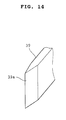
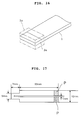
- FIGS. 1, 2, and 3 there are illustrated examples of rapid temperature rise heater elements in the form of ceramic heater elements.
- the rapid temperature rise heater element is preferably configured as a generally rectangular plate and includes a sintered electrically insulating ceramic layer 1, an exothermic section 2, and first and second lead layers 3 and 4.
- the overall configuration of the element is preferably a plate as mentioned above although it may take another form like a cylinder.
- the exothermic section 2 includes first and second sintered high-resistance, conductive ceramic layers 2a and 2b which are formed on the entire area (FIG. 1) or selected areas (FIG. 2) of the upper and rear surfaces of the sintered insulating ceramic layer 1 from a relatively high resistance, conductive ceramic material into a planar or curvilinear plate form.
- the exothermic section 2 further includes a connecting portion 2c which is formed integrally with the first and second sintered high-resistance, conductive ceramic layers 2a and 2b from a relatively high resistance, conductive ceramic material such as to form an electric current path which extends from one to the other of the first and second sintered high-resistance, conductive ceramic layers 2a and 2b around a portion of the periphery of the sintered insulating ceramic layer 1, the distal edge of the sintered insulating ceramic layer 1 in the illustrated embodiments.
- the distal edge is the left edge in FIGS. 1 to 3.
- the first and second lead layers 3 and 4 are formed contiguous to the first and second sintered high-resistance, conductive ceramic layers 2a and 2b.
- steps are provided in the first and second sintered high-resistance, conductive ceramic layers 2a and 2b and the first and second lead layers 3 and 4 are formed on those rear reduced thickness portions of the first and second sintered high-resistance, conductive ceramic layers 2a and 2b which extend rearward from the steps to the rear ends.
- the opposed surfaces of the first and second lead layers 3 and 4 are flush with the opposed surfaces of the first and second sintered high-resistance, conductive ceramic layers 2a and 2b, respectively.
- first and second sintered high-resistance, conductive ceramic layers 2a and 2b are limited to the selected areas of the sintered insulating ceramic layer 1
- the first and second lead layers 3 and 4 are formed on the rear portion of the sintered insulating ceramic layer 1 such that they form surfaces flush with the opposed surfaces of the first and second sintered high-resistance, conductive ceramic layers 2a and 2b.
- the rapid temperature rise heater element is preferably configured as a generally rectangular plate as illustrated in the figures and has the exothermic section 2 formed at the longitudinally distal end of the plate.
- the "exothermic section” used herein is not limited to a resistance layer, but may also include a portion of the sintered insulating ceramic layer 1 along with the resistance layer. More specifically, the exothermic section is a section which serves to develop heat in a substantial sense and designates the distal portion of the element which extends to the distal side from the (distal) edges of the lead layers 3 and 4.
- first and second lead layers 3 and 4 On the first and second lead layers 3 and 4 are formed electrode layers or terminal electrodes 5 and 6 of a metal for external connection.
- the electrode layers 5 and 6 may be disposed at any position on the first and second lead layers 3 and 4. Desirably, the electrode layers 5 and 6 are disposed at or near the other end of the rapid temperature rise heater element which is opposite to the one end where the exothermic section 2 is formed, avoiding the electrode layers 5 and 6 from being heated to high temperature.
- connection portion 2c of the exothermic section 2 is of an increased size, there can be a situation where only the first and second sintered high-resistance, conductive ceramic layers 2a and 2b develop heat, depending on the relative areas of the components.
- a sandwich structure having centrally interleaved a layer 2d having a higher resistance may be provided as shown in FIG. 3 so that the connecting portion 2c will fully develop heat.
- the rapid temperature rise heater element is covered on its outer surface with a protective film which is chemically and thermally stable, heat resistant, and oxidation resistant though not shown.
- the rapid temperature rise heater element has a temperature rise time from room temperature to 1000 to 1500°C set within 10 seconds, preferably 1 to 5 seconds. Also the heater element generally has an element resistance set in the range of 0.5 to 20 k ⁇ although it varies with the ranges of applied power and voltage.
- the exothermic section has an electrical resistance which is higher than the resistance of the first and second lead layers by a factor of about 10 or more, especially by a factor of about 20 to about 1,000. This difference ensures that the terminal electrodes are not heated to an extremely high temperature. Since the resistance value mentioned above will increase by a factor of about 4 due to PTC characteristics when the element develops heat to increase the temperature from room temperature to 1,000°C, one approach is to set the resistance value at room temperature reduced to about a quarter of the target value.
- the rapid temperature rise heater element of the invention is dimensioned so as to have a thickness in the range of about 100 to 2,000 ⁇ m, a width in the range of about 200 to 5,000 ⁇ m, preferably about 800 to 3,000 ⁇ m, and a length in the range of about 15 to 70 mm, preferably about 25 to 50 mm.
- a thickness below the range mechanical strength would be low.
- a thickness beyond the range would lead to a too greater thermal capacity, a slower temperature rise and a lower thermal impact resistance which will cause crack occurrence upon rapid temperature rise.
- a width below the range would lead to low mechanical strength, handling difficulty, and a less thermal capacity.
- the sintered insulating ceramic layer 1 and the first and second sintered high-resistance, conductive ceramic layers 2a and 2b each have a thickness of about 1 to 1,000 ⁇ m, more desirably about 10 to 500 ⁇ m.
- a thickness of less than 1 ⁇ m would lead to insufficient mechanical strength, occurrence of through-holes, and electrical short-circuits.
- a thickness of more than 1,000 ⁇ m would lead to a greater thermal capacity, a slower temperature rise and a possible failure of the element by thermal impact upon rapid temperature rise.
- the exothermic section as a whole has a thickness of about 100 to 2,000 ⁇ m, more desirably about 500 to 1,000 ⁇ m.
- a thickness of less than 100 ⁇ m would lead to insufficient mechanical strength to use in practice.
- the exothermic section Upon long-term operation, the exothermic section would react with an oxidized layer which will be formed in the conductor, resulting in deterioration of insulation.
- a thickness of more than 2,000 ⁇ m would lead to a greater thermal capacity, a time-consuming temperature rise, and low thermal impact resistance.
- the connecting portion 2c of the exothermic section should desirably extend about 200 to 2,000 ⁇ m forward of the distal end of the sintered insulating ceramic layer 1.
- first and second sintered high-resistance, conductive ceramic layers 2a and 2b should desirably be present on the sintered insulating ceramic layer 1, over a length between 100 ⁇ m at minimum, especially 500 ⁇ m at minimum and the length of the sintered insulating ceramic layer 1 at maximum. Within such a length, the exothermic section would have an equally heated region enlarged and the occurrence of cracks upon repetitive temperature rises would be minimized, which provides improvements in thermal impact resistance and durability.
- the exothermic section should preferably occupy 1 to 60%, more preferably 5 to 40% by volume of the entire volume of the element.
- the first and second lead layers 3 and 4 would have a thickness of about 1 to 1,000 ⁇ m.
- the sintered insulating ceramic layer 1 is formed of a ceramic composition composed mainly of a first insulating component in the form of a metal oxide and a second conductive component in the form of a metal silicide and/or a metal carbide. It is acceptable to use only the first insulating component although the addition of the second conductive component thereto is preferred for durability improvement.
- the metal oxide is at least one member in powder form selected from the group consisting of aluminum oxide, zirconium oxide, chromium oxide, titanium oxide, tantalum oxide, silicon oxide, magnesium aluminum oxide and silicon aluminum oxide (for example, mulite 3Al 2 O 3 ⁇ 2SiO 2 and sillimanite Al 2 O 3 ⁇ SiO 2 ).
- the metal silicide is at least one member in powder form selected from the group consisting of molybdenum silicide, tungsten silicide, and chromium silicide; and the metal carbide is at least one member in powder form selected from the group consisting of silicon carbide and titanium carbide.
- the preferred second component is a silicide, especially molybdenum silicide.
- the first insulating component and the second conductive component are desirably mixed in a volume ratio of from 10:0 to 8:2, more preferably from 10:0 to 9.3:0.7, especially from 9.8:0.2 to 9.3:0.7. If the content of the second conductive component exceeds 20% by volume, the material would be more or less conductive since the insulation by the first insulating material is impaired.
- the exothermic section 2 is formed of a ceramic composition composed mainly of a first insulating component in the form of a metal oxide and a second conductive component in the form of a metal silicide and/or a metal carbide.
- the metal oxide, metal silicide and metal carbide may be selected from the same examples as mentioned above.
- the compositional ratio of the first insulating component to the second conductive component in the exothermic section is desirably set to give a volume ratio of from 7.5:2.5 to 5.5:4.5, more preferably from 7:3 to 6:4 provided that these powders have a mean particle size of about 0.2 to 2 ⁇ m. If the content of the second conductive component is less than 25% by volume, the mix material would have a too high resistance. If the content of the second conductive component exceeds 45% by volume, the mix material would have a too low resistance to generate a proper amount of heat.
- the high resistance layer 2d portion contains the first insulating component in a higher ratio than the remaining portion so that the layer 2d has a higher resistance.
- the ratio of the first insulating component in the layer 2d is determined by the resistance values of the first and second sintered high resistance conductive ceramic layers 2a and 2b and the connecting portion 2c which are, in turn, calculated on the basis of their dimensions.
- the first and second lead layers 3 and 4 are formed of a ceramic composition composed mainly of a first insulating component in the form of a metal oxide and a second conductive component in the form of a metal silicide and/or a metal carbide. It is acceptable to use only the second conductive component although the addition of the first insulating component thereto is preferred from the standpoint of durability.
- the metal oxide, metal silicide and metal carbide may be selected from the same examples as mentioned above.
- the first insulating component and the second conductive component are desirably mixed in a volume ratio of from 5:5 to 0:10, more preferably from 5:5 to 1:9. If the content of the second conductive component is less than 50% by volume, the resulting lead layers would have a high resistance causing considerable heat generation.
- the first and second lead layers are layers of a metal or alloy applied by baking, thermal spraying, plating or sputtering, rather than the ceramic layers.
- the metals used herein include, for example, platinum and palladium, and examples of the alloy used herein include stainless steel, nickel-chromium-aluminum, and cobalt and yttrium system alloys such as Ni-Cr-Al-Y, Co-Cr-Al-Y, Ni-Co-Cr-Al-Y, and Ni-Cr.
- the terminal electrodes are formed of palladium, silver, nickel, aluminum and solder, for example.
- electrodes of palladium, silver or nickel are formed by baking and electrodes of aluminum are formed by thermal spraying.
- the protective film is formed of at least one member selected from the group consisting of silica, alumina, titania, chromia, and tin oxide. It has a thickness of about 0.1 to 100 ⁇ m, especially about 1 to 100 ⁇ m.
- the protective film may be formed by any of oxidation, dipping, sol-gel and coating techniques. Note that the dipping technique is to dip the heater element in a solution of the selected metal.
- the sintered insulating ceramic layer, exothermic section, and first and second lead layers are sintered ceramic bodies formed of ceramic compositions predominantly comprising an identical first insulating component and an identical second conductive component, but different in blend ratio of the components. This reinforces the bond between layers and improves durability.
- the respective layers may contain up to 2% by weight of silicon carbide.
- an alkaline earth metal oxide, yttrium oxide or rare earth metal oxide or a compound capable of converting into such an oxide upon firing (for example, carbonates, oxalates and hydroxides) may be contained as a sintering aid.
- one or more oxides of Ca, Ba, Mg, Y, La, Ce, Sm, Dy, and Nd may be contained in an amount of up to 10% by weight, especially 0.1 to 10% by weight.
- both the first insulating component and second conductive component have a particle size of about 1 to 50 ⁇ m.
- a rapid temperature rise heater element can be fabricated by the following method.
- source materials for forming the sintered insulating ceramic layer, exothermic section and lead layers are first prepared. This preparation is carried out by weighing the first insulating component and second conductive component both in powder form in accordance with the blend ratios for the respective layers, and blending them while adding suitable amounts of a binder and solvent thereto.
- the first and second component powders have a mean particle size of about 0.1 to 3 ⁇ m and about 0.5 to 8 ⁇ m, respectively.
- An acrylic binder is the preferred binder.
- Toluene is typically used as the solvent.
- the thus prepared blends are mixed in ball mills, for example, into slurries.
- the mixing time is generally about 3 to 24 hours.
- the slurries are applied by a conventional doctor blade or extrusion technique to form three types of green sheets for the sintered insulating ceramic layer, exothermic section, and lead layers.
- the green sheets have a thickness which is previously determined by calculation such that the layers as fired may have a thickness in the desired range.
- the green sheets are then stacked so as to provide any of the cross-sectional structures shown in FIGS. 1 to 3.
- Layer build-up is preferably carried out by thermo-compression bonding under a pressure of about 50 to 2,000 kg/cm 2 and a temperature of about 50 to 150°C. Layer build-up can be done without forming sheets, that is, by repeatedly applying the respective slurries by a screen printing technique.
- the layered structure is cut into strips conforming to the final heater element configuration. This step requires cutting along the four sides of a rectangular strip at the maximum.
- binder removal is desirably carried out under the following conditions, for example.
- the firing is desirably carried out under the following conditions, for example.
- the firing atmosphere may be vacuum, argon gas, helium gas or hydrogen gas. It is desirable to avoid a nitrogen atmosphere because the exothermic section, if nitrided, will have a negative temperature characteristic.
- the binder removal and firing may be carried out either independently or continuously.
- a protective film is applied on the surface of the thus sintered body.
- This coating may be effected by dipping the sintered body in a dispersion of a coating material or a metal alkoxide solution or an alkoxide solution having a coating material dispersed therein. If the coating material is silica, a silicone resin is applied to the surface of the sintered body, followed by firing.
- terminal electrodes are electrically connected to lead wires or fitted in a socket.
- the thus fabricated rapid temperature rise heater element of the invention finds use as gas igniters and has a drive voltage of about 12 to 400 volts which is commensurate with automotive batteries.
- the ceramic heater element includes an exothermic section which is formed of a sintered ceramic composition containing a molybdenum silicide-aluminum oxide mix material as a major component and at least one additive selected from the group consisting of carbides of Zr, W, Ta, Ti, Nb, Hf, and Mo.
- the carbides used herein are generally in the form of ZrC, WC, TaC, TiC, NbC, HfC, and MoC.
- the molybdenum silicide-aluminum oxide mix material should have a resistivity of 1x10 -2 to 5x10 0 ⁇ cm as sintered. With a resistivity of less than 1x10 -2 ⁇ cm, the material has a too low resistance to serve as a heater. With a resistivity of more than 5x10 0 ⁇ cm, the material has a too high resistance so that a temperature of 1,200°C may not be exceeded.
- molybdenum silicide-aluminum oxide mix material used as a major component of the exothermic section
- molybdenum silicide and aluminum oxide are desirably mixed in a volume ratio of from 40/60 to 15/85, especially from 35/65 to 20/80.
- a molybdenum silicide content of less than 15% by volume would lead to a higher resistance whereas a content of more than 40% by volume would lead to a too low resistance to develop an acceptable amount of heat.
- the molybdenum silicide and aluminum oxide are present as distinct phases in the mix and both have a mean grain size of about 0.2 to 30 ⁇ m.
- the additive in the form of ZrC, WC, TaC, TiC, NbC, HfC, and MoC is preferably contained in a total amount of 0.01 to 10% by volume, more preferably 0.05 to 5% by volume, especially 0.1 to 3% by volume of the ceramic composition. Less than 0.01% by volume of the additive is less effective whereas more than 10% by volume of the additive would render it difficult to fully consolidate the composition when fired without using a hot press.
- the additive is generally present at the grain boundary or association site.
- SiC may be further added to the ceramic composition in an amount of about 0.01 to 2% by volume.
- a binder and solvent are added to the above-mentioned raw materials and mixed to prepare a slurry, which is applied by a doctor blade technique or the like to form a green sheet from which the exothermic section is to be formed.
- the slurry for the exothermic section is sometimes called a resistive slurry.
- the exothermic section should preferably satisfy the following condition.
- the heater element can be heated from room temperature to 1,000°C within 5 seconds, but not overheated to above 1,600°C. If the exothermic section's temperature coefficient of resistance m deviates from the above-defined region in a lower direction, overheating above 1,600°C can occur, and if the same deviates from the above-defined region in an upper direction, rapid heat development would be retarded.
- the exothermic section should preferably be supported by an insulating ceramic layer. More specifically, the ceramic heater element preferably has a structure as shown in FIG. 1.
- the sintered insulating ceramic layer 1 may be similar to that described in the first form.
- the sintered insulating ceramic layer is formed of a ceramic composition composed mainly of aluminum oxide and molybdenum silicide.
- the joint between the sintered insulating ceramic layer and the exothermic section is improved.
- a binder and solvent are added to the above-mentioned raw materials and mixed to prepare a slurry, which is applied by a doctor blade technique or the like to form a green sheet from which the sintered insulating ceramic layer is to be formed.
- the slurry for the sintered insulating ceramic layer is sometimes called an insulating slurry.
- the first and second lead layers 3 and 4 may be the same as in the first form.
- the lead layers desirably use a ceramic composition composed mainly of aluminum oxide and molybdenum silicide.
- the sintered insulating ceramic layer, exothermic section and lead layers are formed of ceramic compositions composed of identical major components, the joint of the lead layers to the sintered insulating ceramic layer and the exothermic section is improved.
- a binder and solvent are added to the above-mentioned raw materials and mixed to prepare a slurry, which is applied by a doctor blade technique or the like to form a green sheet from which the lead layers are to be formed.
- the slurry for the lead layers is sometimes called a conductive slurry.
- the ceramic heater element of the second form has the same dimensions as in the first form.
- the ceramic heater element is covered on its outer surface with a protective film which is chemically and thermally stable, heat resistant, and oxidation resistant though not shown.
- the protective film is formed of the same material as in the first form, with silica being especially preferred.
- the protective film may be formed by any of oxidation, dipping, sol-gel and coating techniques, with the oxidation technique being preferred. It is most desirable to form silica on the surface of the heater element by conducting electricity through the element in an oxidizing atmosphere, for example, air, thereby causing the element to develop heat to a higher temperature than the normal operating state.
- Such conventional ceramic heater elements especially ceramic rapid temperature rise heater elements have the problem that if the size is increased for providing a greater thermal capacity, the exothermic section be subject to cracking or failure by thermal expansion upon rapid temperature rise. This problem is aggravated by the use of molybdenum silicide having a higher coefficient of thermal expansion.
- the structure is improved for mitigating the stresses induced by thermal expansion for preventing cracking and failure.
- the exothermic section is provided with a space for relieving stresses in the exemplary form of a slit or small apertures to substantially divide the exothermic section into two or more zones whereby stress induction is suppressed to prevent cracking and failure of the entire exothermic section.
- the ceramic heater element of the second form is fabricated as follows. The following description refers to the fabrication of a ceramic heater element of the structure shown in FIG. 1.
- source materials for forming the sintered insulating ceramic layer, exothermic section and lead layers are first prepared. This preparation is carried out by weighing the first insulating component (inclusive of aluminum oxide as a major component in the exothermic section) and the second conductive component (inclusive of molybdenum disilicide as another major component in the exothermic section) both in powder form in accordance with the blend ratios for the respective layers, and blending them while adding the additive or metal carbide thereto as well as a binder and solvent.
- the thus prepared blends are mixed in ball mills, for example, into insulating, resistive and conductive slurries.
- the mixing time is generally about 3 to 24 hours.
- three types of green sheets are formed for the sintered insulating ceramic layer, exothermic section, and lead layers.
- the green sheets are then stacked so as to provide the cross-sectional structure shown in FIG. 1.
- Layer build-up is preferably carried out by thermo-compression bonding under a pressure of about 50 to 2,000 kg/cm 2 and a temperature of about 50 to 150°C.
- the layered structure is cut into strips conforming to the final heater element configuration. This step requires cutting along the four sides of a rectangular strip at the maximum.
- binder removal is desirably carried out under the following conditions, for example.
- the firing is desirably carried out under the following conditions, for example.
- the firing atmosphere may be vacuum, argon gas, helium gas or hydrogen gas.
- terminal electrodes are electrically connected to lead wires or fitted in a socket.
- a protective film is formed on the surface of the sintered body of the heater element.
- the protective film is formed by conducting electricity through the element in an oxidizing atmosphere, thereby causing the element to develop heat to a higher temperature.
- the temperature at which the protective film is formed is higher than the temperature encountered during normal operation. If the temperature encountered during normal operation is 1,300°C, for example, the protective film-forming temperature should be higher than that temperature, especially above 1,400°C. It is then desirable that the amount of the metal carbide added to the exothermic section-forming composition is determined by taking into account the protective film-forming temperature.
- a protective film may be formed on the surface of the sintered body by dipping the sintered body in a dispersion of a coating material or a metal alkoxide solution or an alkoxide solution having a coating material dispersed therein. If the coating material is silica, a silicone resin is applied to the surface of the sintered body, followed by firing. Where the protective film is formed by immersion in such a dispersion, the terminal electrodes should be formed subsequent to formation of the protective film.
- the thus fabricated rapid temperature rise heater element finds use as gas igniters and has a drive voltage of about 12 to 400 volts which is commensurate with automotive batteries.
- the ceramic heater element uses a conductor containing a silicide as a conductive substance and has a dense silicon oxide protective film formed on the surface of the element.
- the conductor contains a metal silicide which is preferably at least one member selected from the group consisting of silicides of molybdenum, tungsten, and chromium.
- the conductor may further contain another conductive substance in the form of a metal carbide.
- the metal carbide used herein is at least one member selected from the group consisting of carbides of silicon and titanium.
- the metal silicide should be present in an amount of at least 0.1% by volume of the conductor material.
- an insulating substance in the form of a metal oxide is contained in the conductor material for controlling the resistance value thereof.
- the metal oxide used herein is preferably at least one powder member selected from the group consisting of aluminum oxide, zirconium oxide, chromium oxide, titanium oxide, tantalum oxide, magnesium aluminum oxide, and mulite.
- the insulating substance is sometimes referred to as a first insulating component and the conductive substance is sometimes referred to as a second conductive component.
- the conductor material is used as the exothermic section of the ceramic heater element, it should preferably be formulated such that the compositional ratio of the second conductive component to the first insulating component may range from 40/60 to 15/85, especially from 35/65 to 20/80 by volume. If the volume of the conductive component is larger, the conductor material would have a too low resistivity to provide a difference in resistance from the leads, failing to ensure concentrated heat development within the exothermic section. If the volume of the conductive component is smaller, the conductor material would have a very high resistivity approximate to that of an insulator and inhibit conduction of substantial current, failing to provide the function of a heater element.
- SiC Silicon carbide
- the amount of SiC added is up to 10% by volume of the conductor material.
- Conductor material with more than 10% by volume of SiC is less susceptible to sintering, not fully consolidated, and less reliable as a heater element. If added, SiC should be present in an amount of more than 0.01% by volume.
- a dense silicon oxide protective film is formed on the surface of a conductor material by conducting electricity through the conductor material in an oxidizing atmosphere for a suitable time such that the conductor material itself may be heated to a high temperature of at least 1,000°C. Then SiO 2 forms on the conductor surface and constitutes at 1,000°C or higher a sufficiently dense film to prevent further diffusion of oxygen.
- the heater element contains molybdenum disilicide MoSi 2 , for example, during the electric conduction heating process, MoSi 2 in the vicinity of the element surface reacts with O 2 to form a dense silicon oxide protective film according to the following scheme. 5MoSi 2 + 7O 2 ⁇ Mo 5 Si 3 + 7SiO 2
- the dense silicon oxide protective film is desired to be free of needle crystals of silicon oxide.
- the silicon oxide protective film has a thickness of about 0.01 to 20 ⁇ m, especially about 0.1 to 2 ⁇ m.
- a film of less than 0.1 ⁇ m thick is susceptible to damages or flaws and does not fully serve for the protective function.
- the oxidizing atmosphere referred to above is an atmosphere containing more than 5% of oxygen. Higher oxygen concentrations are desirable. Most preferably, heat treatment is carried out in 100% oxygen or an atmosphere of steam-containing air.
- the conductor In order for the silicon oxide protective film to form, the conductor should reach a temperature of at least 1,000°C during electric conduction. No dense silicon oxide protective film forms at temperatures below 1,000°C.
- the upper limit temperature reached by electric conduction heating is not critical although it is generally about 1,800°C from the standpoint of a heater element.
- the temperature reached by electric conduction heating is desirably higher than the temperature the heater element encounters during normal operation, that is, the temperature to which the conductor will heat up during use. The reason will be described later.
- the conductor is preferably maintained in a non-oxidizing atmosphere while the conductor is at a temperature below 1,000°C, especially in the range of 400 to 800°C. If an oxidizing atmosphere prevails in this temperature range, there can be formed acicular crystals of silicon oxide, which remain even after the conductor is heated to above 1,000°C. Then the protective film becomes porous, allowing the element to be oxidized during operation, resulting in a variation of the resistance value thereof.
- the preferred non-oxidizing atmosphere is an argon gas atmosphere.
- the electric conduction time is desirably about 1 to 5 hours. A shorter time would not allow for development of a dense oxide film whereas a longer time would provide no further advantages and lead to a higher cost.
- the heating rate is about 1 minute from room temperature to 1,000°C and cooling is non-forced cooling.
- the heating conditions mentioned above are achieved by applying a voltage which is 5 to 50% higher than the normal operating voltage.
- the exothermic section should preferably be supported by an insulating ceramic layer. More specifically, the ceramic heater element preferably has a structure as shown in FIG. 1.
- the exothermic section 2 of the ceramic heater element is desirably formed of a conductor of the above-defined composition.
- the sintered insulating ceramic layer 1 may be formed of a composition as previously mentioned in the first form, preferably a ceramic composition composed mainly of aluminum oxide and molybdenum silicide. When the sintered insulating ceramic layer is formed of a ceramic composition composed of identical major components to those of the exothermic section, the joint between the sintered insulating ceramic layer and the exothermic section is improved.
- the first and second lead layers 3 and 4 may be the same as in the first form.
- the lead layers desirably use a ceramic composition composed mainly of aluminum oxide and molybdenum silicide.
- a ceramic composition composed mainly of aluminum oxide and molybdenum silicide.
- exothermic section and lead layers-are formed of ceramic compositions composed of identical major components the joint of the lead layers to the sintered insulating ceramic layer and the exothermic section is improved.
- a silicon oxide protective film is also formed on selected areas of the lead layers.
- the ceramic heater element of the third form has the same dimensions as in the first form.
- Such conventional ceramic heater elements especially ceramic rapid temperature rise heater elements have the problem that if the size is increased for providing a greater thermal capacity, the exothermic section be subject to cracking or failure by thermal expansion upon rapid temperature rise. This problem is aggravated by the use of molybdenum silicide having a higher coefficient of thermal expansion.
- the structure is improved for mitigating the stresses induced by thermal expansion for preventing cracking and failure.
- the exothermic section is provided with a space for relieving stresses in the exemplary form of a slit or small apertures to substantially divide the exothermic section into two or more zones whereby stress induction is suppressed to prevent cracking and failure of the entire exothermic section.
- the stress relieving space is illustrated in FIG. 5 as a single slit which extends longitudinally through the element structure from the distal (left) end to an intermediate point.
- the stress relieving space in the ceramic heater element may have any desired shape as long as it can mitigate stresses induced in the exothermic section without causing a substantial change in the resistance value thereof. Then the space may be either a slit as mentioned above or a plurality of small apertures uniformly distributed over the entire area of the exothermic section.
- a silicon oxide protective film can be formed on the exothermic section by applying a voltage across the terminal electrodes to cause the exothermic section to develop heat.
- the first and second lead layers contain a metal silicide
- electric conduction is preferably controlled such that a silicon oxide protective film is also formed on those portions of the lead layers which extend from the exothermic section over a certain length.
- silicon oxide forms at temperatures above 400°C. Then the element is heated such that those portions of the lead layers which will reach temperatures above 400°C during normal operation may reach a temperature above 1,000°C whereupon a dense silicon oxide protective film is formed on those portions for preventing those portions from being oxidized during subsequent operation.
- the remaining portions of the lead layers that is, those portions of the lead layers which are disposed adjacent to the terminal electrodes do not reach a temperature above 400°C during normal operation of the heater element and are not oxidized. Then on the remaining portions of the lead layers, a silicon oxide film may be present or absent or acicular crystals of silicon oxide may be present.
- the ceramic heater element of the third form can be fabricated by generally following the process of fabricating the ceramic heater element of the second form including an exothermic section composed mainly of a molybdenum silicide-aluminum oxide mix material from the source powder preparing step to the firing step.
- terminal electrodes After firing, silver or suitable metal is baked to the surface of the first and second lead layers at predetermined positions to form terminal electrodes, completing the manufacture of a ceramic rapid temperature rise heater element. Further, the terminal electrodes may be electrically connected to lead wires or fitted in a socket.
- a protective film is formed on the surface of the sintered body of the heater element.
- the protective film is formed by conducting electricity through the element in an oxidizing atmosphere, thereby causing the element to develop heat to a higher temperature.
- the conditions of electric conduction for self heating are as mentioned above.
- the thus fabricated rapid temperature rise heater element of the invention also finds use as gas igniters and has a drive voltage of about 12 to 400 volts which is commensurate with automotive batteries.
- the ceramic heater element is a molybdenum silicide system material element comprising a main body of a material composed mainly of molybdenum silicide.
- the molybdenum silicide is typically molybdenum disilicide.
- the element further includes terminal electrodes of an electrode material containing at least one first component selected from the group consisting of Mo, W, and Si and at least one second component selected from the group consisting of Fe, Co, and Ni.
- the terminal electrodes Preferably have an electrical resistance of less than 10 m ⁇ .
- the electrode material contains at least molybdenum (Mo) in an amount of 70 to 100% by weight of the first component.
- the second component is contained in an amount of 30 to 90%, more preferably 50 to 80%, most preferably 60 to 70% by weight of the total weight of the electrode material.
- the electrode material contains at least tungsten (W) in an amount of 70 to 100% by weight of the first component.
- the second component is contained in an amount of 18 to 83%, more preferably 34 to 68%, most preferably 44 to 55% by weight of the total weight of the electrode material.
- the electrode material contains at least silicon (Si) in an amount of 70 to 100% by weight of the first component.
- the second component is contained in an amount of 65 to 97%, more preferably 81 to 95%, most preferably 87 to 91% by weight of the total weight of the electrode material.
- the content of the second component is limited as above because higher contents above the range would reduce the bond strength between the element and the electrodes whereas lower contents below the range would reduce the bond strength between the electrodes and solder.
- molybdenum (Mo) and nickel (Ni) are used as the first and second components, respectively.
- nickel is contained in an amount of 70 to 100% by weight of the second component.
- the terminal electrodes of the above-mentioned composition are formed on a molybdenum silicide system material element as follows.
- An electrode-forming paste is first prepared.
- the paste is prepared by weighing raw material powders in accordance with the desired compositional ratio, adding a binder and solvent to the powders, and fully mixing the ingredients.
- the binders used herein include methacrylic, ethyl cellulose, and polyvinyl alcohol binders.
- the solvents used herein include toluene, xylene, ⁇ -terpineol, methanol and ethanol. Mixing may be wet mixing using a ball mill or the like. The mixing time is about 5 to 48 hours though not critical.
- the electrode-forming paste is then applied to predetermined positions of the element by screen printing techniques and then baked to complete formation of electrodes.
- Baking uses a neutral or reducing atmosphere.
- the neutral and reducing atmospheres include argon gas, helium gas, nitrogen gas, nitrogen gas-hydrogen gas mixtures, and vacuum.
- the baking temperature is preferably set in the range of 1,050 to 1,400°C for a molybdenum base electrode material, 1,100 to 1,450°C for a tungsten base electrode material, or 950 to 1,300°C for a silicon base electrode material. If the baking temperature is below the range, the electrodes would bond to the element at low or little bond strength. If the baking temperature is above the range, a metal component of the electrode material would diffuse into the element, reducing the amount of metal retained in the electrode or promoting separation of the metal component to cause electrode stripping.
- the molybdenum silicide system material element as one exemplary ceramic heater element preferably has the structure shown in FIG. 1, for example.
- the heater element is preferably configured as a generally rectangular plate and includes a sintered insulating ceramic layer 1, an exothermic section 2, and first and second lead layers 3 and 4.
- the exothermic section 2 includes first and second sintered high-resistance, conductive ceramic layers 2a and 2b which are formed on the entire area of the upper and rear surfaces of the sintered insulating ceramic layer 1 from a relatively high resistance, conductive ceramic material and a connecting portion 2c which is formed integrally with the first and second sintered high-resistance, conductive ceramic layers 2a and 2b from a relatively high resistance, conductive ceramic material such as to form an electric current path which extends from one to the other of the first and second sintered high-resistance, conductive ceramic layers 2a and 2b around the distal (left) edge of the sintered insulating ceramic layer 1.
- the first and second lead layers 3 and 4 are formed contiguous to the first and second sintered high-resistance, conductive ceramic layers 2a and 2b.
- the heater element is preferably configured as a generally rectangular plate as illustrated in the figure and has the exothermic section 2 formed at the longitudinally distal end of the plate.
- the exothermic section includes a portion of the sintered insulating ceramic layer 1 along with the resistance layer.
- the sintered insulating ceramic layer, exothermic section and first and second lead layers are formed of ceramic compositions composed mainly of a first insulating component in the form of a metal oxide and a second conductive component in the form of a metal silicide and/or a metal carbide.
- a first insulating component in the form of a metal oxide
- a second conductive component in the form of a metal silicide and/or a metal carbide.
- the sintered insulating ceramic layer it is acceptable to use only the first insulating component although the addition of the second conductive component thereto is preferred for durability improvement.
- the first and second lead layers it is acceptable to use only the second conductive component although the addition of the first insulating component thereto is preferred because the joint between the first and second sintered high-resistance, conductive ceramic layers and the first and second lead layers is improved.
- at least the first and second lead layers, preferably the first and second sintered high-resistance, conductive ceramic layers and the first and second lead layers
- the metal oxide is at least one member in powder form selected from the group consisting of aluminum oxide, zirconium oxide, chromium oxide, titanium oxide, tantalum oxide, magnesium aluminum oxide, and mulite as previously mentioned.
- the metal silicide may include at least one member in powder form selected from the group consisting of tungsten silicide and chromium silicide.
- the metal carbide is at least one member in powder form selected from the group consisting of silicon carbide and titanium.carbide as previously mentioned.
- the first insulating component and the second conductive component are desirably mixed in a volume ratio of from 10:0 to 8:2, more preferably from 10:0 to 9.3:0.7. If the content of the second conductive component exceeds 20% by volume, the material would be more or less conductive since the insulation by the first insulating material is impaired.
- a binder and solvent are added to the above-mentioned raw materials and mixed to prepare a slurry, which is applied by a doctor blade technique or the like to form a green sheet from which the sintered insulating ceramic layer is to be formed.
- the slurry for the sintered insulating ceramic layer is sometimes called an insulating slurry.
- the first insulating component and the second conductive component are desirably mixed in a volume ratio of from 5:5 to 0:10, more preferably from 5:5 to 1:9. If the content of the second conductive component is less than 50% by volume, the resulting lead layers would have a high resistance causing considerable heat generation.
- the lead layers should be constructed from a molybdenum silicide base material because terminal electrodes are formed thereon according to the fourth form.
- a binder and solvent are added to the above-mentioned raw materials and mixed to prepare a slurry, which is applied by a doctor blade technique or the like to form a green sheet from which the lead layers are to be formed.
- the slurry for the lead layers is sometimes called a conductive slurry.
- the first insulating component and the second conductive component are desirably mixed in a volume ratio of from 60:40 to 85:15, more preferably from 65:35 to 80:20. If the content of the first insulating component exceeds the range, the material would have a greater resistivity which requires an enlargement of cross-sectional area to provide a desired resistance value, which is less tolerant to thermal cycling. If the content of the first insulating component is below the range, the material would have a lower resistivity which requires a reduction of cross-sectional area to provide a desired resistance value, which leads to low mechanical strength.
- a binder and solvent are added to the above-mentioned raw materials and mixed to prepare a slurry, which is applied by a doctor blade technique or the like to form a green sheet from which the exothermic section is to be formed.
- the slurry for the exothermic section is sometimes called a resistive slurry.
- the ceramic heater element of the fourth form has the same dimensions as in the first form.
- the ceramic heater element is covered on its outer surface with a protective film which is chemically and thermally stable, heat resistant, and oxidation resistant though not shown.
- the protective film is formed of at least one member selected from the group consisting of silica, alumina, and chromia, with silica being especially preferred. It is about 0.1 to 100 ⁇ m thick.
- the protective film may be formed by any of oxidation, dipping, sol-gel and coating techniques as previously mentioned, with the oxidation technique being preferred. It is most desirable to form silica on the surface of the heater element by conducting electricity through the element in an oxidizing atmosphere, for example, air, thereby causing the element to develop heat to a higher temperature than the normal operating state, typically to a temperature of higher than 1,000°C.
- Such conventional ceramic heater elements especially ceramic rapid temperature rise heater elements have the problem that if the size is increased for providing a greater thermal capacity, the exothermic section be subject to cracking or rupture by thermal expansion upon rapid temperature rise. This problem is aggravated by the use of molybdenum silicide having a higher coefficient of thermal expansion.
- the structure is improved for mitigating the stresses induced by thermal expansion for preventing cracking and rupture. More particularly, the exothermic section is provided with a space for relieving stresses in the exemplary form of a slit or small apertures to substantially divide the exothermic section into two or more zones whereby stress induction is suppressed to prevent cracking and failure of the entire exothermic section. This constitutes the fifth form as will be described later.
- the stress relieving space is illustrated in FIG. 5 as a single slit which extends longitudinally through the element structure from the distal (left) end to an intermediate point.
- the stress relieving space in the ceramic heater element may have any desired shape as long as it can mitigate stresses induced in the exothermic section without causing a substantial change in the resistance value thereof. Then the space may be either a slit as mentioned above or a plurality of small apertures uniformly distributed over the entire area of the exothermic section.
- the ceramic heater element of the fourth form is fabricated as follows. The following description refers to the fabrication of a ceramic heater element of the structure shown in FIG. 1.
- source materials for forming the sintered insulating ceramic layer, exothermic section and lead layers are first prepared. This preparation is carried out by weighing the first insulating component and second conductive component both in powder form in accordance with the blend ratios for the respective layers, and blending them while adding an optional additive in the form of a metal carbide thereto as well as a binder and solvent.
- the thus prepared blends are mixed in ball mills, for example, into insulating, resistive and conductive slurries.
- the mixing time is generally about 3 to 24 hours.
- three types of green sheets are formed for the sintered insulating ceramic layer, exothermic section, and lead layers.
- the green sheets have a thickness which is previously determined by calculation such that the layers as fired may have a thickness in the desired range.
- the green sheets are then stacked so as to provide the cross-sectional structure shown in FIG. 1.
- Layer build-up is preferably carried out by thermo-compression bonding under a pressure of about 50 to 2,000 kg/cm 2 and a temperature of about 50 to 150°C.
- the layered structure is cut into strips conforming to the final heater element configuration. This step requires cutting along the four sides of a rectangular strip at the maximum.
- binder removal and firing After cutting, discrete elements are subject to binder removal and firing.
- the binder removal is desirably carried out under the following conditions, for example, a heating rate of 6-300°C/hour, especially 30-120°C/hour, a holding temperature of 900-1100°C, especially 950-1050°C, a holding time of 1-24 hours, especially 5-20 hours, and an atmosphere of air, nitrogen gas, argon gas or nitrogen gas-hydrogen-steam mixture.
- the firing is desirably carried out under the following conditions, for example, a heating rate of 300-2000°C/hour, especially 500-1000°C/hour, a holding temperature of 1400-1850°C, especially 1700-1800°C, a holding time of 1/2-3 hours, especially 1-2 hours, and a cooling rate of 300-2000°C/hour, especially 500-1000°C/hour.
- the firing atmosphere may be vacuum, argon gas, helium gas or hydrogen gas. It is desirable to avoid a nitrogen atmosphere because the exothermic section will become insulating if nitrided to form silicon nitride.
- the binder removal and firing may be carried out either independently or continuously.
- an electrode-forming paste as defined above is applied and baked to the surface of the first and second lead layers at predetermined positions to form terminal electrodes, completing the manufacture of a ceramic heater element. Further, the terminal electrodes may be electrically connected to lead wires or fitted in a socket.
- a protective film is formed on the surface of the sintered body of the heater element.
- the protective film is formed by conducting electricity through the element in an oxidizing atmosphere, thereby causing the element to develop heat to a higher temperature above 1,000°C.
- the temperature at which the protective film is formed is higher than the temperature encountered during normal operation. If the temperature encountered during normal operation is 1,300°C, for example, the protective film-forming temperature should be higher than that temperature, especially above 1,400°C.
- a protective film may be formed on the surface of the sintered body by dipping the sintered body in a dispersion of a coating material or a metal alkoxide solution or an alkoxide solution having a coating material dispersed therein. If the coating material is silica, a silicone resin is applied to the surface of the sintered body, followed by firing. Where the protective film is formed by immersion in such a dispersion, the terminal electrodes should be formed subsequent to formation of the protective film.
- the thus fabricated ceramic heater element also finds use as gas igniters and has a drive voltage of about 12 to 400 volts which is commensurate with automotive batteries.
- the fifth form is directed to a ceramic heater element which is provided with means for relieving stresses, typically a slit.
- FIGS. 5 to 8 Preferred examples of the slit heater element are shown in FIGS. 5 to 8.
- the heater elements of FIGS. 5, 7, and 8 correspond to those of FIGS. 1, 2, and 3 except that a slit is formed as the stress relieving means.
- Like parts are designated by the same numerals.
- the rapid temperature rise heater element of FIG. 5, 7 or 8 is preferably configured as a generally rectangular plate and includes a sintered insulating ceramic layer 1, an exothermic section 2, and first and second lead layers 3 and 4.
- the overall configuration of the element is preferably a plate as mentioned above although it may take another form like a cylinder.
- the exothermic section 2 includes first and second sintered high-resistance, conductive ceramic layers 2a and 2b which are formed on the entire area (FIG. 5) or selected areas (FIG.
- the first and second lead layers 3 and 4 are formed contiguous to the first and second sintered high-resistance, conductive ceramic layers 2a and 2b.
- steps are provided in the first and second sintered high-resistance, conductive ceramic layers 2a and 2b and the first and second lead layers 3 and 4 are formed on those rear reduced thickness portions of the first and second sintered high-resistance, conductive ceramic layers 2a and 2b which extend rearward from the steps to the rear ends.
- steps are provided in the first and second sintered high-resistance, conductive ceramic layers 2a and 2b and the first and second lead layers 3 and 4 are formed on those rear reduced thickness portions of the first and second sintered high-resistance, conductive ceramic layers 2a and 2b which extend rearward from the steps to the rear ends.
- the rapid temperature rise heater element is preferably configured as a generally rectangular plate as illustrated in the figures and has the exothermic section 2 formed at the longitudinally distal end of the plate.
- first and second lead layers 3 and 4 On the first and second lead layers 3 and 4 are formed electrode layers or terminal electrodes 5 and 6 of a metal for external connection.
- the electrode layers 5 and 6 may be disposed at any position on the first and second lead layers 3 and 4. Desirably, the electrode layers 5 and 6 are disposed at or near the other end of the rapid temperature rise heater element which is opposite to the one end where the exothermic section 2 is formed, avoiding the electrode layers 5 and 6 from being heated to high temperature.
- connection portion 2c of the exothermic section 2 is of an increased size, there can be a situation where only the first and second sintered high-resistance, conductive ceramic layers 2a and 2b develop heat, depending on the relative areas of the components.
- a sandwich structure having centrally interleaved a layer 2d having a higher resistance may be provided as shown in FIG. 8 so that the connecting portion 2c will fully develop heat.
- the element is provided with stress relieving means in the exemplary form of a slit 7.
- the slit 7 extends longitudinally through the exothermic section 2 from the distal (left) end of the element toward the electrodes 5 and 6, that is, along the current path.
- the slit structure is equivalent to a structure wherein the exothermic section or its electrical resistance is divided into two parallel parts. The slit does not induce a substantial change in the overall resistance value of the exothermic section.
- the slit 7 extends throughout the first and second sintered high-resistance, conductive ceramic layers 2a, 2b and sintered insulating ceramic layer 1. The slit 7 need not reach the distal end.
- the slit 7 need not necessarily reach the lead layers 3 and 4. Differently stated, it suffices that only the exothermic section be provided with a slit extending a longitudinal partial distance thereof. Most preferably, the slit 7 should extend throughout the exothermic section 2 and further rearward (rightward) through the lead layers 3 and 4 as shown in FIGS. 5, 7 and 8.
- the slit 7 has a width of about 0.1 to 2 mm, preferably about 0.1 to 1 mm though not critical.
- the stress relieving space in the ceramic heater element may have any desired shape as long as it can mitigate stresses induced in the exothermic section without causing a substantial change in the resistance value thereof. Then the space may be either a slit as mentioned above or a plurality of small apertures uniformly distributed over the entire area of the exothermic section.
- the ceramic heater element is desirably covered on its outer surface with a protective film which is chemically and thermally stable, heat resistant, and oxidation resistant though not shown.
- composition, formation, and dimensions of the respective layers and protective film are the same as previously described in conjunction with FIGS. 1 to 3.
- the sintered insulating ceramic layer 1 and the exothermic section 2 are formed of ceramic compositions composed mainly of a first insulating component in the form of a metal oxide and a second conductive component in the form of a metal silicide and/or a metal carbide.
- the first insulating component occupies the majority for the insulating ceramic layer 1 whereas the second conductive component occupies more for the exothermic section 2.
- the metal oxide, metal silicide and metal carbide may be selected from the same examples as previously mentioned.
- the blend ratio of the first insulating component to the second conductive component in the exothermic section 2 (excluding the sintered insulating ceramic layer 1), which is largely affected by the particle size distribution, is desirably set to give a volume ratio of from 7.5:2.5 to 5.5:4.5, more preferably from 7:3 to 6:4 provided that these powders have a mean particle size of about 0.2 to 2 ⁇ m. If the content of the second conductive component is less than 25% by volume, the mix material would have a too high resistance. If the content of the second conductive component exceeds 45% by volume, the mix material would have a too low resistance to generate a proper amount of heat.
- the high resistance layer 2d portion contains the first insulating component in a higher ratio than the remaining portion so that the layer 2d has a higher resistance.
- the ratio of the first insulating component in the layer 2d is determined by the resistance values of the first and second sintered high resistance conductive ceramic layers 2a and 2b and the connecting portion 2c which are, in turn, calculated on the basis of their dimensions.
- the ceramic compositions may contain up to 2% by weight of silicon carbide and/or titanium carbide.
- the first insulating component and second conductive component have a particle size of about 0.1 to 50 ⁇ m and about 0.5 to 50 ⁇ m, respectively.
- the above-mentioned rapid temperature rise heater element with a slit are preferably fabricated as follows.
- source material powders, slurries, and green sheets are successively prepared by following the procedures previously described in conjunction with FIGS. 1 to 3.
- Layer build-up is preferably carried out by thermo-compression bonding under a pressure of about 50 to 2,000 kg/cm 2 and a temperature of about 50 to 150°C. Layer build-up can be done without forming sheets, that is, by repeatedly applying the respective slurries by a screen printing technique.
- the layered structure is cut into strips conforming to the final heater element configuration. Thereafter, using a rotary cutter, a slit is machined in the strip or element. Alternatively, using a punching machine, a plurality of small apertures are perforated in the strip.
- discrete elements are subject to binder removal and firing under the same conditions as previously mentioned in the first form.
- a protective film is applied on the surface of the thus sintered body.
- This coating may be effected by dipping the sintered body in a dispersion of a coating material or a metal alkoxide solution or an alkoxide solution having a coating material dispersed therein. If the coating material is silica, a silicone resin is applied to the surface of the sintered body, followed by firing.
- terminal electrodes are electrically connected to lead wires or fitted in a socket.
- the thus fabricated rapid temperature rise heater element also finds use as gas igniters and has a drive voltage of about 12 to 400 volts which is commensurate with automotive batteries.
- the stress relieving means contemplated in the fifth form of the invention is applicable not only to the ceramic rapid temperature rise heater elements shown in FIGS. 5 to 8, but also to a ceramic rapid temperature rise heater element of another structure as shown in FIGS. 9 and 10.
- the ceramic rapid temperature rise heater element generally designated at 10 is of rectangular shape and includes a ceramic insulator 11 having upper and lower layers 11a and 11b and an exothermic resistor 12 (in the form of a thin wire strip as shown by phantom lines) embedded in the insulator 11. More particularly, the exothermic resistor 12 is interleaved between the upper and lower layers 11a and 11b.
- An exothermic section 13 is defined in one end portion of the element 10.
- the exothermic resistor 12 is configured to a generally M shape in the exothermic section 13 as best shown in FIG. 10.
- the element 10 at the one end portion is provided with a stress relieving means in the exemplary form of a slit 14.
- the slit 14 desirably extends into the recess of the M shape of the exothermic resistor 12 as best shown in FIG. 10.
- the stress relieving space may have any location and shape insofar as the exothermic resistor 12 is not split thereby. Therefore, in the embodiment the stress relieving means may also take the form of a plurality of apertures. It is understood that in the ceramic rapid temperature rise heater element of this structure, the insulator 11 need not have both the upper and lower layers, the use of a single insulator layer being acceptable.
- the ceramic heater elements of the foregoing examples and embodiments are fabricated using green sheets for the respective layers.
- the green sheets are generally prepared from slurry by means of a doctor blade apparatus.
- a typical, preferred embodiment of the doctor blade apparatus is illustrated in FIGS. 11 to 15.
- the doctor blade apparatus generally designated at 30 is used to form a plurality of slurry layers on a base film 31 traveling in one horizontal direction.
- the apparatus 30 includes a container 32 disposed on the base film in close contact therewith.
- the container 32 has vertical walls 33, 34, 35, and 36 defining a generally rectangular shape in a horizontal cross section. More particularly, the container 32 is contoured by a pair of spaced apart side walls 33 and 34 extending in the base film travel direction and a pair of front and rear walls 35 and 36 spaced apart in the base film travel direction.
- the walls are fixedly joined to adjacent ones at their edges with adhesive or mechanical fastening means.
- the rear wall 36 is a downstream wall of the container 32 in the travel direction of the base film 31.
- the lower side or edge of the rear wall 36 is vertically spaced a predetermined distance from the base film 31 so that the lower edge serves as a doctor blade 37. Between the doctor blade 37 and the base film 31 is defined a gap 38 for allowing slurry to outflow.
- the doctor blade 37 is provided separately from the rear wall 36 so that the doctor blade 37 may be vertically movable for adjusting the gap 38 for allowing green sheets of different thicknesses to be formed.
- the rear wall 36 having the doctor blade 37 integrally formed therewith is vertically movable.
- the container 32 is partitioned into a plurality of slurry receiving compartments 40 by at least one partition 39 which is disposed in the container and extends in the traveling direction of the base film or parallel to the side walls 33, 34 (two partitions 38 shown in FIG. 11).
- the partition 39 includes a downstream end or slurry outflow portion 39a having a transverse width which is tapered to a point in the traveling direction of the base film as best shown in FIG. 14. That is, the transverse width of the portion 39a is gradually reduced in the slurry outflow direction. This tapering to a point ensures that green sheet regions applied by the doctor blade 37 adjoin to adjacent ones at their edges.
- a control system is provided in conjunction with the doctor blade apparatus 30 as shown in FIG. 15.
- Feed means in the form of tanks 41 are provided for feeding slurries to the respective compartments 40.
- Level detectors 42 are associated with the respective compartments 40 for detecting the level of slurry therein.
- a controller 50 is coupled with the feed tanks 41 and the detectors 42 for controlling the level of slurry in each compartment constant. Upon receipt of a level detection signal from a detector 42, the controller 50 delivers a control signal to the corresponding feed tank 41 to feed a controlled amount of slurry to the corresponding compartment 40, thereby maintaining the levels of slurries in the compartments 40 at an approximately equal predetermined height.
- each slurry feeder 41 is coupled with a solvent feed tank 43 (which is common to all the feeders in FIG. 15) and provided with a slurry viscometer 44.
- the controller 50 is also coupled with the tank 43 and the viscometer 44. Upon receipt of a slurry viscosity signal from a viscometer 44, the controller 50 delivers a control signal to a corresponding valve 43a associated with the solvent feed tank 43 for opening and closing the valve 43a to feed a controlled amount of solvent to the corresponding tank 41, thereby adjusting the slurry in each feed tank 41 to a predetermined viscosity.
- the compartments are charged with slurries of different compositions or containing different materials.
- the base film is moved across the apparatus.
- a plurality of strip segments S1, S2 and S3 of different compositions are applied to the base film 31 concurrently and in parallel.
- the strip segments S1, S2 and S3 adjoin adjacent ones along their sides.
- a ceramic green sheet including strip segments of different compositions joined along the adjacent sides.
- ceramic green sheet segments adjoin adjacent ones along their longitudinal edges immediately after they are applied or coated. Then the materials intermix at the boundary to integrate the segments. This ensures a firm close joint between adjacent ceramic green sheet segments.
- the slurries from which the ceramic green sheet segments are formed are prepared by selecting source powders for the respective layers, adding a binder, plasticizer, solvent and other additives to the powder mix, and mixing the ingredients.
- the slurries are adjusted to a viscosity of about 5 to 50 Ps, more preferably about 15 to 25 Ps, depending on the width of the respective ceramic green sheet segments.
- two pastes are desirably adjusted to have viscosities as close to each other as possible. More preferably, the two pastes are adjusted to have a viscosity difference within about ⁇ 1 Ps because stability upon casting is expectable.
- the slurries are received in the compartments to an approximately equal and constant height. Then the slurries are applied under an equal and constant pressure, preventing warpage of the edges of ceramic green sheet segments.
- mutually miscible solvents especially an identical solvent can be used in preparing the slurries from which the ceramic green sheet segments are formed.
- exemplary solvents include alcohol solvents such as methanol, ethanol and isopropyl alcohol, aromatic solvents such as toluene, benzene and xylene, ketone solvents such as acetone, ether solvents, and halogenated solvents such as methylene chloride.
- the doctor blade apparatus mentioned above is especially suitable for use in forming a green sheet including two different regions as shown in FIG. 16.
- the green sheet shown in FIG. 16 includes a sintered insulating ceramic layer 1 and a portion 2e of a connecting portion 2c within the confine of an exothermic section 2, the layer 1 and the portion 2e forming an integral sheet on a common plane.
- a ceramic rapid temperature rise heater element of the structure shown in FIG. 1, for example is fabricated.
- the resulting heater element has been fully described in this disclosure.
- the heater element may have a stress relieving means in the exemplary form of a slit as shown in FIG. 5.
- source materials are prepared for the sintered insulating ceramic layer, exothermic section and lead layer. More particularly, a first insulating component and a second conductive component both in powder form are weighed in accordance with the blend ratios desired for the sintered insulating ceramic layer, exothermic section and lead layer. A binder, solvent and other necessary additives are added to the powder mixtures.
- the combined ingredients are mixed in a ball mill, for example, to form insulating, resistive and conductive slurries.
- the milling time is about 3 to 24 hours, for example.
- five green sheets G1 to G5 are formed as shown in FIG. 1.
- outermost green sheets G1 and G5 each include a green sheet segment formed from the resistive slurry and another green sheet segment formed from the conductive slurry.
- the center green sheet G3 includes a green sheet segment formed from the resistive slurry and another green sheet segment formed from the insulating slurry.
- the interleaving green sheets G2 and G4 are formed solely from the resistive slurry.
- green sheets G1, G3, and G5 are formed using the doctor blade apparatus of the sixth form.
- a green sheet consisting of a plurality of ceramic green sheet segments like green sheets G1, G3, and G5 the slurry feed tanks 41 are charged with a desired number of slurries and deliver the slurries to the corresponding compartments 40 of the apparatus while adjusting the viscosity thereof. Then a green sheet consisting of segments is formed on a base film by means of the doctor blade apparatus 30.
- Plain green sheets like green sheets G2 and G4 formed of a single composition may be prepared by any conventional technique such as doctor blade and extrusion techniques.
- the green sheets have a thickness which is previously determined by calculation such that the layers as fired may have a thickness in the desired range.
- the green sheets are then stacked so as to provide the cross-sectional structure shown in FIG. 1.
- Layer build-up is preferably carried out by thermo-compression bonding under a pressure of about 50 to 2,000 kg/cm 2 and a temperature of about 50 to 150°C.
- the layered structure is cut into strips conforming to the final heater element configuration. This step requires cutting along the four sides of a rectangular strip at the maximum.
- the binder removal is desirably carried out under the following conditions, for example, a heating rate of 6-300°C/hour, especially 30-120°C/hour; a holding temperature of 250-380°C, especially 300-350°C; a holding time of 1-24 hours, especially 5-20 hours; and an atmosphere of air, nitrogen gas, argon gas or nitrogen gas-steam mixture.
- the firing is desirably carried out under the following conditions, for example, a heating rate of 300-2000°C/hour, especially 500-1000°C/hour; a holding temperature of 1400-1700°C, especially 1500-1650°C; a holding time of 1/2-3 hours, especially 1-2 hours; and a cooling rate of 300-2000°C/hour, especially 500-1000°C/hour.
- the firing atmosphere may be vacuum, argon gas, helium gas, hydrogen gas or nitrogen gas.
- the binder removal and firing may be carried out either independently or continuously.
- terminal electrodes are electrically connected to lead wires or fitted in a socket.
- the thus fabricated rapid temperature rise heater element finds use as gas igniters and has a drive voltage of about 12 to 400 volts which is commensurate with automotive batteries.
- the compact was cut to dimensions as shown in Table 1 (the indicated dimensions were those after firing) so as to provide the layer structure shown in FIG. 1 (excluding the terminal electrodes).
- the cut compact was subject to binder removal in a nitrogen gas atmosphere by heating to 350°C at a rate of 1°C/min., holding at the temperature for 5 hours, then heating again to 900°C at a rate of 5°C/min., holding at the temperature for 2 hours, and then cooling at 5°C/min.
- the binder-free compact was then fired in vacuum by heating to 1,650°C at a rate of 5°C/min., holding at the temperature for 1 hour, and thereafter cooling at a rate of 300°C/min. After the compact was cooled to 800°C, it was allowed to cool in the furnace.
- the resulting element was coated with silicone over the entire surface and subjected to heat treatment in air at 1,300°C for 1 hour to form a silica protective film of about 1 ⁇ m thick. Portions of the protective film where terminal electrodes were to be attached were abraded off by sand blasting and silver paste was baked to those portions to form terminal electrodes.
- rapid temperature rise heater element samples Nos. 12 to 19 (inventive samples: Nos. 12 and 13, comparative samples: Nos. 14 to 19).
- Also prepared was a rapid temperature rise heater element sample, No. 11 falling within the scope of the invention in which the sintered insulating ceramic layer, exothermic section, and first and second lead layers were formed from the respective slurries by a screen printing technique. In all the samples, the exothermic section and the lead layers had a resistance ratio of 50:1.
- inventive sample Nos. 11 to 13 had a room temperature to 1,100°C rise time within 10 seconds, a crack occurrence of 0%, and a resistance change within 5%. Comparative samples could not satisfy one or more of the requirements: a rise time within 10 seconds, crack occurrence of 0%, and a resistance change within 5%. In sample Nos. 11 to 13, the exothermic section occupied 10 to 20% of the entire volume of the element.
- Sample Nos. 21 to 24 were fabricated by the same procedure as Example 1 except that the element was dimensioned to 800 ⁇ m thick, 1,800 ⁇ m wide, and 35 mm long and the blend ratio between Al 2 O 3 and MoSi 2 was changed as shown in Table 2. These samples were measured for a temperature rise time and a percent resistance change by the same test procedures as above. The results are shown in Table 2.
- the inventive sample satisfied all the above-mentioned requirements whereas the comparative samples did not satisfy one or more of the requirements.
- Sample Nos. 30 to 40 were fabricated by the same procedure as sample No. 21 of Example 2 except that the first and second components of the ceramic compositions were changed and combined as shown in Table 3. These samples were measured for a temperature rise time and a percent resistance change by the same test procedures as above. The results are shown in Table 3. Sample No.
- test results were substantially equivalent to the above-reported results.
- TiC was added in an amount of 0, 0.001, 0.01, 0.1, 1, 5, 10, and 15% by volume.
- the source powders had a mean particle size of 0.5 ⁇ m.
- a 1-liter alumina pot was charged with each mix in a total amount of 100 grams and 1/2 liter of alumina balls with a diameter of 5 mm. With ethanol added, the mix was wet milled for 24 hours. At the end of milling, the mix was poured into a high-temperature resin vat where it was dried at 100°C in air. The mix was further fully mixed in an alumina mortar.
- the mix was placed in a rod-shaped cavity of a mold and compacted under a pressure of 1 t/cm 2 .
- the compact was fired at 1,800°C in an argon gas atmosphere. It was held at 1,800°C for 2 hours and then allowed to cool.
- the sintered compact was machined to the shape shown in FIG. 17. As indicated in FIG. 17, the dimensions were 40 mm in overall length, 10 mm in overall width, and 1 mm in thickness.
- the compact was heat treated at 1,400°C in air for one hour to form a protective film of silica on the surface.
- the samples were measured for a resistance ratio R, a temperature rise time from room temperature to 1,000°C, and a saturation temperature.
- the resistance ratio R was determined by measuring the resistance Rr (in ⁇ ) of a sample at room temperature and the resistance R1100 (in ⁇ ) at 1,100°C by means of a digital multi-meter manufactured by Advanced Test Co. and dividing the resistance R1100 by the resistance Rr.
- Temperature was measured by a dichroic optical pyrometer manufactured by Chino K.K. The results are shown in Table 4. Sample No.
- Additional heater element samples were prepared by the same procedure as above except that the additive was changed from TiC to ZrC, WC, TaC, NbC, HfC and MoC in the amount reported in Table 5.
- the resistance ratio R was similarly measured. The results are shown in Table 5.
- Resistance ratio R Amount (vol%) Additive ZrC WC TaC NbC HfC MoC 0.001 4 4 4 4 4 4 0.1 3.0 2.9 2.9 3.0 2.9 2.9 1 2.1 2.0 2.0 2.0 2.0 2.0 10 1.2 1.1 1.1 1.0 1.1 1.1 15 0.3 0.5 0.5 0.4 0.5 0.5
- heater elements of the structure shown in FIG. 1 were fabricated and subjected to an exothermic test.
- the ingredients were mixed for 24 hours to form slurries. Green sheets were formed from these slurries by a doctor blade technique. The sheets were cut to predetermined dimensions so that the structure of FIG. 1 might be constructed. The sheets were stacked in a mold in a layer arrangement. The stack was compacted at a pressure of 500 kg/cm 2 and a temperature of 120°C to join the insulator, resistor and conductor layers together to provide a compact of the layer structure shown in FIG. 1 (excluding the terminal electrodes).
- the compact was subject to binder removal in a nitrogen gas atmosphere in an alumina tubular furnace by heating to 1,000°C at a rate of 1°C/min., holding at the temperature for 1 hour, and then allowing to cool down.
- the binder-free compact was then fired in an argon atmosphere by heating from room temperature to 1,400°C in 1 hour, then heating from 1,400°C to 1,800°C in 30 minutes, holding at the temperature for 1 hour, and thereafter cooling at a rate of 300°C/min. After the compact was cooled to 800°C, it was allowed to cool in the furnace.
- the resulting element was coated with silicone over the entire surface and subjected to heat treatment in air at 1,400°C for 1 hour to form a dense silica protective film of about 1 ⁇ m thick. Selected portions of the protective film where terminal electrodes were to be attached were abraded off by sand blasting and silver paste was baked to those portions to form terminal electrodes. In this way, there were obtained rapid temperature rise heater element samples.
- the element was dimensioned to 2.0 mm wide, 25.0 mm long and 1.0 mm thick.
- the samples were subject to an exothermic test under the following conditions.
- the inventive samples reached 1,000°C within 2 seconds and a maximum (saturation) temperature of 1,480°C in 4 seconds after the start of electric conduction and dropped to about 90°C in 20 seconds after the interruption of electric conduction.
- Ceramic heater elements of the structure shown in FIG. 1 were fabricated.
- aluminum oxide Al 2 O 3 and molybdenum silicide MoSi 2 powders were commonly used as major components of ceramic compositions from which the sintered insulating ceramic layer, exothermic section, and lead layers were to be formed. These components were blended as shown below.
- Al 2 O 3 MoSi 2 Sintered insulating ceramic layer (insulator layer) 100 vol% 0 vol% Exothermic section (resistor layer) 70 vol% 30 vol%
- the ingredients were mixed for 24 hours to form slurries. Green sheets were formed from these slurries by a doctor blade technique. The sheets were cut to predetermined dimensions so that the structure of FIG. 1 might be constructed.
- the sheets were stacked in a mold in a layer arrangement. The stack was compacted at a pressure of 500 kg/cm 2 and a temperature of 120°C to join the insulator, resistor and conductor layers together to provide a compact of the layer structure shown in FIG. 1 (excluding the terminal electrodes).
- the compact was cut to predetermined dimensions.
- the compact was subject to binder removal in a nitrogen gas atmosphere in a furnace and then fired in an argon atmosphere at 1,800°C for 2 hours.
- a Pd-Ag paste was applied to opposed end portions of the sintered compact, dried and baked at 1,000°C to form electrodes.
- Nickel-plated soft copper conductor pieces were electrically welded to the electrodes.
- heater element samples were dimensioned to 2 mm wide, 40 mm long and 1 mm thick while the exothermic section (defined remote from the electrodes) had a length of 7 mm in a longitudinal direction.
- a voltage of 28 V was applied across one sample such that the maximum temperature region reached 1,700°C and maintained one hour to form an oxide film on the maximum temperature region.
- the processing atmosphere was argon gas until the element temperature exceeded 600°C and thereafter switched to air.
- the element sample was analyzed on the surface by electron probe microanalysis (EPMA) to find that a dense silicon oxide protective film covered the entire surface of the exothermic section and portions of the lead layers to a distance of about 4 mm from the boundary with the exothermic section, needle-shaped silicon oxide formed over an adjacent zone of about 1 mm, and no silicon oxide formed in the remaining surfaces extending to the electrodes.
- the silicon oxide film on the exothermic section was 10 ⁇ m thick.
- the electrically conducted sample and the control (no electric conduction) sample were exposed to a flame of propane gas to examine the time taken when the percent resistance (at room temperature) change between before and after flame exposure exceeded 50%. The time was 20 hours in the case of the control sample. The electrically conducted sample had a resistance change of only 7% over 1,000 hours of flame exposure.
- a protective film was similarly formed on another element sample except that the exotherm temperature was 900°C.
- a similar flame tolerance test was carried out to find that the electrical resistance increased 50% at 200 hours.
- Samples were similarly treated to form a silicon oxide protective film except that the exotherm temperature during electric conduction was changed from 1,700°C to 1,500°C, 1,300°C, 1,200°C and 900°C. Electric conduction was maintained for one hour.
- the thus treated samples were operated by continuously conducting electricity to develop heat to a service temperature of 1,300°C over 1,000 hours. At the end of the 1000-hour continuous heat development, the samples were measured for resistance, from which a percent resistance change was calculated. The results are shown in Table 6.
- the self-heating temperature during electric conduction for forming a silicon oxide protective film should be above 1,000°C, desirably above the service or operating temperature.
- molybdenum (Mo) and nickel (Ni) were used as first and second components. They were both powders and had a mean particle size of 1 ⁇ m.
- a substrate in the form of a plate was prepared by mixing MoSi 2 and Al 2 O 3 in a volume ratio of 8/2 and firing the mixture to 99% of the theoretical density. Both the source powders had a mean particle size of 0.5 ⁇ m.
- the electrode-forming paste was applied by screen printing to the plate over an area of 2 x 2 mm (as baked). With five areas assigned to each type of paste, 30 areas in total were printed on one plate. At the end of printing, the pastes were dried in air at 150°C for 1/2 hour.
- the plates having electrodes printed thereon were baked in a baking furnace with a graphite heater in an argon gas stream at temperatures of 1,000°C, 1,050°C, 1,100°C, 1,200°C, 1,300°C, 1,400°C, and 1,500°C.
- the heating time was 1 hour
- the baking time was 1/2 hour
- the cooling was unforced cooling.
- Electrode composition Mo (wt%) 100 80 70 40 10 0 Ni (wt%) 0 20 30 60 90 100 Heat treatment temperature (°C) Resistance (m ⁇ ) 1000 0.2 0.3 0.1 0.1 1050 0.3 0.4 0.3 0.1 1100 2.0x10 7 0.5 0.4 0.5 0.2 1200 1.5x10 7 0.7 0.7 2.5 UM 1300 20.3 0.9 2.3 5.7 UM 1400 2.0x10 7 5.7 3.8 8.0 9.0 UM 1500 1.5x10 7 2.1 57.9 UM UM UM UM UM UM UM UM
- the bonding force was measured by applying adhesive tape to the electrode, stripping the tape therefrom and observing the state of the electrode. Samples were rated good (O) when the electrode was not separated, fair ( ⁇ ) when partially separated, and rejected (X) when entirely separated together with the adhesive tape. The results are shown in Table 8.
- Electrode composition Mo (wt%) 100 80 70 40 10 0 Ni (wt%) 0 20 30 60 90 100 Heat treatment temperature (°C) Adhesive tape test 1000 X X X X ⁇ ⁇ 1050 X X ⁇ ⁇ O X 1100 X O O O O X 1200 X ⁇ O O O X 1300 X X O O ⁇ X 1400 X X O ⁇ ⁇ X 1500 X X X X X X X X X X X
- Samples were prepared by the same procedure as in Example 6 except that the first and second components of the electrode material were changed as shown in Table 9 and all pastes were baked at 1,200°C to form electrodes.
- the samples were subject to a tensile strength test.
- One end of a copper wire having a diameter of 0.6 mm and a length of 50 mm was pressed to form an enlarged head in the form of a disk having a diameter of 1 mm.
- the wire was placed relative to the sample such that the head was in contact with the electrode surface (2 x 2 mm). With cream solder applied, a heat treatment was effected to solder the wire head to the electrode, completing a test specimen.
- the specimen was set in a tensile tester where with the sample fixedly secured, the wire was pulled upward perpendicular to the specimen. The pulling force when the sample was separated from the wire or the solder was measured. Samples were rated according to the following criterion. Rating Tensile strength OO > 3 kg/cm 2 O 2 - 3 kg/cm 2 ⁇ 1 - 2 kg/cm 2 X ⁇ 1 kg/cm 2
- the second component when Mo is the majority of the first component, the second component should preferably be contained in an amount of 30 to 90%, more preferably 50 to 80%, most preferably 60 to 70% by weight of the electrode material; when W is the majority of the first component, the second component should preferably be contained in an amount of 18 to 83%, more preferably 34 to 68%, most preferably 44 to 55% by weight of the electrode material; and when Si is the majority of the first component, the second component should preferably be contained in an amount of 65 to 97%, more preferably 81 to 95%, most preferably 87 to 91% by weight of the electrode material.
- Ceramic heater elements of the structure shown in FIG. 1 were fabricated.
- aluminum oxide Al 2 O 3 and molybdenum silicide MoSi 2 powders were commonly used as major components of ceramic compositions from which the sintered insulating ceramic layer, exothermic section and first and second lead layers were to be formed. These components were blended as shown below.
- Al 2 O 3 MoSi 2 Sintered insulating ceramic layer (insulator layer) 100 vol% 0 vol% Exothermic section (resistor layer) 70 vol% 30 vol%
- Powder's mean particle size 0.4 ⁇ m 2 ⁇ m
- the ingredients were mixed for 24 hours to form slurries. Green sheets were formed from these slurries by a doctor blade technique. The sheets were cut to predetermined dimensions so that the structure of FIG. 1 might be constructed. The sheets were stacked in a mold in a layer arrangement. The stack was compacted at a pressure of 500 kg/cm 2 and a temperature of 120°C to join the insulator, resistor and conductor layers together to provide a compact of the layer structure shown in FIG. 1 (excluding the terminal electrodes).
- the compact was subject to binder removal in a nitrogen gas atmosphere in an alumina tubular furnace by heating to 1,000°C at a rate of 1°C/min., holding at the temperature for 1 hour, and then allowing to cool down.
- the binder-free compact was then fired in an argon atmosphere by heating from room temperature to 1,400°C in 1 hour, then heating from 1,400°C to 1,800°C in 30 minutes, holding at the temperature for 1 hour, and thereafter cooling at a rate of 300°C/min. After the compact was cooled to 800°C, it was allowed to cool in the furnace.
- the resulting element was coated with silicone over the entire surface and subjected to heat treatment in air at 1,400°C for 1 hour to form a dense silica protective film of about 1 ⁇ m thick. Selected portions of the protective film where terminal electrodes were to be attached were abraded off by sand blasting and an electrode-forming paste of 40Mo-60Ni (Example 6) was baked to those portions at 1,200°C to form terminal electrodes. In this way, there was obtained a rapid temperature rise heater element sample. The element was dimensioned to 2.0 mm wide, 25.0 mm long and 1.0 mm thick. The sample showed equivalent performance to the sample of Example 6.
- Ceramic heater elements of the structure shown in FIG. 5 were fabricated.
- aluminum oxide Al 2 O 3 and molybdenum silicide MoSi 2 powders were commonly used as major components of ceramic compositions from which the sintered insulating ceramic layer, exothermic section and first and second lead layers were to be formed. These components were blended as shown below.
- Al 2 O 3 MoSi 2 Sintered insulating ceramic layer (insulator layer) 100 vol% 0 vol% Exothermic section (resistor layer) 70 vol% 30 vol%
- the 100 compacts (50 plain compacts + 50 slit compacts) were subject to binder removal in a nitrogen gas atmosphere in an alumina tubular furnace by heating to 1,000°C at a rate of 1°C/min., holding at the temperature for 1 hour, and then allowing to cool down.
- the binder-free compacts were then fired in an argon atmosphere by heating from room temperature to 1,400°C in 1 hour, then heating from 1,400°C to 1,800°C in 30 minutes, holding at the temperature for 1 hour, and thereafter cooling at a rate of 300°C/min. After the compact was cooled to 800°C, it was allowed to cool in the furnace.
- the resulting elements were coated with silicone over the entire surface and subjected to heat treatment in air at 1,400°C for 1 hour to form a dense silica protective film of about 1 ⁇ m thick. Selected portions of the protective film where terminal electrodes were to be attached were abraded off by sand blasting and a silver paste was baked to those portions to form terminal electrodes. In this way, there were obtained 100 rapid temperature rise heater element samples (50 plain elements + 50 slit elements). The elements were dimensioned to 6.0 mm wide, 25.0 mm long and 1.0 mm thick. The slit was 0.2 mm wide. The halves of the exothermic section defined between the side wall and the slit and affording a current path were 2.9 mm wide.
- the samples were subject to an exotherm test under the conditions: an initial resistance of 5 ⁇ , an applied voltage of 20 V, and a load of 27 W.
- An on-off test consisting of 10 seconds electric conduction and 20 seconds interruption was carried out.
- both the plain and slit samples reached a maximum temperature of 1,250°C in 5 seconds after the start of electric conduction and dropped to about 90°C in 20 seconds after the interruption of electric conduction.
- An insulating slurry was prepared by adding a methacrylic binder and toluene solvent to Al 2 O 3 powder having a mean particle size of 0.4 ⁇ m and milling the ingredients.
- a resistive slurry was prepared by adding a methacrylic binder and toluene solvent to MoSi 2 powder having a mean particle size of 2 ⁇ m and milling the ingredients. From the insulating slurry, an insulating layer 11b was formed as shown in FIG. 10. Using the resistive slurry, a resistor pattern 12 was printed on the insulating layer 11b as shown in FIG. 10. The insulating slurry was applied thereon to cover the printed resistor 12 with another insulating layer (11a in FIG. 9).
- the layer structure was compacted at a pressure of 500 kg/cm 2 and a temperature of 120°C to join the insulator, resistor and insulator layers together to provide a compact of the layer structure shown in FIG. 9. There were prepared 100 compacts which were divided into two groups.
- the 100 compacts (50 plain compacts + 50 slit compacts) were subject to binder removal in a nitrogen gas atmosphere in an alumina tubular furnace by heating to 1,000°C at a rate of 1°C/min., holding at the temperature for 1 hour, and then allowing to cool down.
- the binder-free compacts were then fired in vacuum by heating from room temperature to 1,600°C over 3 hours, holding at the temperature for 1 hour, and thereafter cooling at a rate of 300°C/min. After the compact was cooled to 800°C, it was allowed to cool in the furnace. Those portions of a protective film covering the electrode terminals were abraded off by sand blasting and a silver paste was baked to those portions to form terminal electrodes. In this way, there were obtained 100 rapid temperature rise heater element samples (50 plain elements + 50 slit elements). The elements were dimensioned to 6.0 mm wide, 25.0 mm long and 1.0 mm thick. The slit was 0.2 mm wide.
- Formation of a slit ensures manufacture of ceramic heater elements having improved thermal impact resistance and increased capacity.
- Ceramic heater elements of the structure shown in FIG. 1 were fabricated. First, aluminum oxide Al 2 O 3 powder having a mean particle size of 1.0 ⁇ m as the first insulating component and molybdenum silicide MoSi 2 powder having a mean particle size of 2 to 5 ⁇ m as the second conductive component were weighed in accordance with the following blend ratios intended for the sintered insulating ceramic layer, exothermic section, and lead layers. Al 2 O 3 MoSi 2 Sintered insulating ceramic layer 100 vol% 0 vol% Sintered high resistance conductive ceramic layer 70 vol% 30 vol% Lead layers 20 vol% 80 vol%
- To the source powders were added 10 to 20% by weight of an acrylic binder, 2 to 5% by weight of a plasticizer in the for of n-butyl phthalyl or n-butyl glycolate, 15 to 20% by weight of ethanol solvent, and 30 to 40% by weight of toluene in accordance with the formulation for the respective layers. These ingredients were milled for 24 to 48 hours in a ball mill to form insulating, resistive and conductive slurries. The slurries were taken out of the mills, deaerated in vacuum and adjusted to a viscosity of 15 to 25 Ps.
- a doctor blade apparatus as shown in FIG. 11 was assembled.
- the partition was set at a position corresponding to the widths of the insulating and conductive segments, for example.
- a doctor blade apparatus was specialized for a particular sheet.
- the viscosity adjusted slurries were supplied into the compartments and coated onto a base film to form a green sheet consisting of two strip segments.
- the sheet was about 100 ⁇ m thick.
- Three types of green sheets G1, G3 and G5 were obtained in this way.
- single composition sheets, that is, green sheets G2 and G4 were prepared from only the resistive slurry by a conventional doctor blade technique.
- the green sheets were peeled off from the base films, stacked and subjected to thermo-compression bonding to provide the layer structure shown in FIG. 1.
- the layer arrangement was cut to a predetermined shape and heat treated in a nitrogen atmosphere at 900 to 1,100°C for 1 to 2 hours for removing organic matter. Then it was fired in an argon atmosphere at 1,700 to 1,800°C for 1 to 2 hours.
- a Pd-Ag paste was baked to the sintered body at one end to form electrodes, to which a nickel-plated soft copper conductor pieces were spot welded.
- the sintered body was placed in a ceramic holder of steatite and bonded with high-temperature cement to complete a ceramic rapid temperature rise heater element.
- the thus fabricated heater elements were subjected to temperature rise and thermal cycling tests. With a voltage of 15 V applied, the exothermic section reached 1,000°C within about 2 seconds, indicating that the heater elements were capable of rapid temperature rise.
- the thermal cycling test between room temperature and 1,500°C was carried out by applying a voltage of 20 V for 10 seconds and turning off for 20 seconds.
- Conventional heater elements failed at 10,000 cycles in the case of less durable elements and at 50,000 cycles in the case of relatively durable elements because cracks occurred at the boundary between different compositions and the electrical resistance increased at that point.
- the ceramic heater elements fabricated according to the invention were free of cracks and experienced a resistance change of less than 10% even at 100,000 cycles, indicating tolerance to thermal cycling.
Landscapes
- Engineering & Computer Science (AREA)
- Chemical & Material Sciences (AREA)
- Ceramic Engineering (AREA)
- Composite Materials (AREA)
- Manufacturing & Machinery (AREA)
- Materials Engineering (AREA)
- Structural Engineering (AREA)
- Organic Chemistry (AREA)
- Combustion & Propulsion (AREA)
- Mechanical Engineering (AREA)
- General Engineering & Computer Science (AREA)
- Resistance Heating (AREA)
Claims (27)
- Elément chauffant à montée rapide en température comportant une couche (1) de céramique frittée isolante généralement rectangulaire ayant une première et une seconde surface principale opposées et des extrémités longitudinalement opposées,un tronçon exothermique (2) s'étendant à partir des première et seconde surfaces principales de la couche de céramique frittée isolante (1), à travers une première extrémité de celle-ci, et constitué d'un matériau de céramique conductrice à résistance élevée,dans lequel des première et seconde couches formant conducteur (3, 4) sont disposées sur la première et la seconde surface principale opposées de la couche de céramique frittée isolante (1), respectivement, en contact avec le tronçon exothermique (2) et formées à partir d'un matériau conducteur à faible résistance,de sorte que lorsqu'une tension est appliquée à travers le tronçon exothermique par l'intermédiaire des première et seconde couches formant conducteur (3,4), le tronçon exothermique (2) développe de la chaleur.
- Elément chauffant selon la revendication 1, dans lequel l'élément a une épaisseur d'environ 100 à 2000 µm, une largeur d'environ 200 à 5000 µm, et une longueur d'environ 15 à 70 mm, ladite couche de céramique frittée isolante (1) ayant une épaisseur d'environ 1 à 1000 µm, et ledit tronçon exothermique (2) ayant une épaisseur totale d'environ 100 à 2000 µm.
- Elément chauffant selon la revendication 1 ou la revendication 2, dans lequel ladite couche de céramique frittée isolante (1), ledit tronçon exothermique (2) et lesdites couches formant conducteur (3, 4) sont formés de compositions de céramique composées principalement d'un premier composant isolant ayant la forme d'un oxyde métallique identique et d'un second composant conducteur ayant la forme d'un siliciure métallique et/ou d'un carbure métallique identique, lesdits premier et second composants étant mélangés selon un rapport volumique de 10/0 à 8/2 pour ladite couche de céramique frittée isolante (1), de 7,5/2,5 à 5,5/4,5 pour ledit tronçon exothermique, et de 5/5 à 0/10 pour lesdites couches formant conducteur (3,4).
- Elément chauffant selon la revendication 3, dans lequelledit oxyde métallique est sélectionné parmi l'oxyde d'aluminium, l'oxyde de zirconium, l'oxyde de chrome, l'oxyde de titane, l'oxyde de tantale, l'oxyde de silicium, l'oxyde de magnésium aluminium, l'oxyde de silicium aluminium et des mélanges de ceux-ci,ledit siliciure métallique est sélectionné parmi le siliciure de molybdène, le siliciure de tungstène, le siliciure de chrome et des mélanges de ceux-ci, etledit carbure métallique est sélectionné parmi le carbure de silicium, le carbure de titane et des mélanges de ceux-ci.
- Elément chauffant selon l'une quelconque des revendications précédentes, qui comporte un film de protection recouvrant la surface extérieure de l'élément, ledit film de protection étant chimiquement et thermiquement stable, résistant à la chaleur, et résistant à l'oxydation, et formé d'au moins un élément parmi la silice, l'alumine et l'oxyde de chrome.
- Elément chauffant selon l'une quelconque des revendications précédentes, dans lequel au moins un parmi ladite couche de céramique frittée isolante (1), ledit tronçon exothermique (2) et lesdites couches formant conducteur (3, 4) contient jusqu'a 2 % en poids de carbure de silicium.
- Elément chauffant selon l'une quelconque des revendications précédentes, dans lequel le tronçon exothermique (2) comporte une première et une seconde couche de céramique frittée conductrice à résistance élevée (2a, 2b) formées sur ladite couche de céramique frittée isolante (1) en appliquant une céramique conductrice à résistance élevée sur au moins des parties des surfaces principales opposées de celle-ci, respectivement, une partie de connexion (2c) étant formée en un seul bloc avec lesdites première et seconde couches de céramique frittée conductrice à résistance élevée (2a, 2b) à travers la céramique conductrice à résistance élevée, un trajet de courant électrique s'étendant à partir de ladite première (2a) vers ladite seconde couche de céramique frittée conductrice à résistance élevée (2b) par l'intermédiaire de ladite partie de connexion (2c), les première et seconde couches formant conducteur (3, 4) étant disposées sur les mêmes surfaces principales opposées que lesdites première et seconde couches de céramique frittée conductrice à résistance élevée (2a, 2b) ou au moins des parties des surfaces desdites première et seconde couches de céramique frittée conductrice à résistance élevée (2a, 2b) et étant reliées électriquement auxdites première et seconde couches de céramique frittée conductrice à résistance élevée (2a, 2b), et ladite partie de connexion (2c) comportant au moins trois couches, parmi lesquelles une couche intermédiaire (2d) a une résistance électrique plus grande que les couches extérieures.
- Elément chauffant selon la revendication 7, dans lequel ladite couche intermédiaire (2d) a une épaisseur qui est sensiblement égale à l'épaisseur de ladite couche de céramique frittée isolante (1) ou diffère au maximum de ± 20 % de celle-ci et est formée contiguë au bord de ladite couche de céramique frittée isolante (1).
- Elément chauffant selon l'une quelconque des revendications précédentes, dans lequel lesdites première et seconde couches formant conducteur (3,4) ont une résistance électrique qui n'est pas plus grande que 1/10 de la résistance dudit tronçon exothermique (2).
- Elément chauffant selon l'une quelconque des revendications précédentes, dans lequel au moins un parmi ladite couche de céramique frittée isolante (1), ledit tronçon exothermique (2) et lesdites couches formant conducteur (3, 4) contient jusqu'à 10 % en poids d'un oxyde de métal alcalino-terreux, d'yttrium ou de métal des terres rares.
- Elément chauffant selon l'une quelconque des revendications précédentes, comportant un tronçon exothermique (2) qui est formé d'une composition de céramique frittée contenant un mélange de siliciure de molybdène et d'oxyde d'aluminium ayant une résistivité de 1 × 10⁻² à 5 × 100 Ωcm en tant que composant principal et 0,01 à 10 % en volume, de préférence de 0,05 à 5 % en volume d'au moins un additif sélectionné parmi des carbures de Zr, W, Ta, Ti, Nb, Hf et Mo.
- Elément chauffant selon la revendication 11, dans lequel la composition est sélectionnée de telle sorte que lorsque le rapport R de la résistivité du tronçon exothermique (2) à une température d'au moins 1000°C à la résistivité du tronçon exothermique à 20°C est reportée sur les ordonnées et la température de l'élément T (en °C) est reportée sur les abscisses d'un graphique, ledit tronçon exothermique a un coefficient de résistance en fonction de la température tombant dans la zone définie et délimitée par la droite
- Elément chauffant selon la revendication 11 ou la revendication 12, qui comporte en outre un film de protection recouvrant la surface extérieure de l'élément, ledit film de protection étant chimiquement et thermiquement stable, résistant à la chaleur, et résistant à l'oxydation et formé d'au moins un élément parmi la silice, l'alumine et l'oxyde de chrome.
- Elément chauffant selon la revendication 5 ou la revendication 13, dans lequel la surface extérieure du conducteur contient un siliciure et le film de protection est constitué d'oxyde de silicium formé par l'étape consistant à :faire passer de l'électricité à travers la surface contenant du siliciure de l'élément dans une atmosphère oxydante pendant un temps prédéterminé de sorte que la surface elle-même est chauffée à une température d'au moins 1000°C, en formant ainsi un film de protection dense en oxyde de silicium sur la surface de l'élément.
- Elément chauffant selon la revendication 14, dans lequel la température à laquelle la surface est chauffée par conduction électrique est plus élevée que la température à laquelle la surface va être chauffée pendant l'utilisation.
- Elément chauffant selon la revendication 14 ou la revendication 15, dans lequel pendant le passage d'électricité, la surface est maintenue dans une atmosphère non-oxydante tant que la surface est à une température située dans la plage de 400 à 800°C.
- Elément chauffant selon l'une quelconque des revendications 14 à 16, dans lequel le matériau de céramique conductrice contient un siliciure, le tronçon exothermique (2) a ledit film de protection en oxyde de silicium formé sur celui-ci, et dans lequel le film de protection en oxyde de silicium formé par autochauffage s étend uniquement sur le tronçon exothermique (2) et les parties desdites première et seconde couches formant conducteur (3, 4) contiguës à celui-ci.
- Elément chauffant selon l'une quelconque des revendications précédentes, dont le corps principal est constitué principalement de siliciure de molybdène, ayant une électrode de borne fixée sur celui-ci, dans lequel le matériau d'électrode contient un premier composant sélectionné parmi Mo, W, Si et des mélanges de ceux-ci et un second composant sélectionné parmi Fe, Co, Ni et des mélanges de ceux-ci.
- Elément chauffant selon la revendication 18, dans lequel ledit matériau d'électrode contient Mo en une quantité de 70 à 100 % en poids du premier composant et le second composant en une quantité de 30 à 90 % en poids du poids total dudit matériau d'électrode.
- Elément chauffant selon la revendication 18, dans lequel ledit matériau d'électrode contient W en une quantité de 70 à 100 % en poids du premier composant et le second composant en une quantité de 18 à 83 % en poids du poids total dudit matériau d'électrode.
- Elément chauffant selon la revendication 18, dans lequel ledit matériau d'électrode contient Si en une quantité de 70 à 100 % en poids du premier composant et le second composant en une quantité de 65 à 97 % en poids du poids total dudit matériau d'électrode.
- Elément chauffant selon l'une quelconque des revendications 19, 20 ou 21, dans lequel l'électrode de borne est formée par cuisson du matériau d'électrode sur le corps principal à une température située dans la plage de 1050 à 1400°C selon la revendication 19, 1100 à 1450°C selon la revendication 20, ou 950 à 1300°C selon la revendication 21.
- Elément chauffant selon l'une quelconque des revendications 19 à 21, dans lequel le matériau d'électrode contient Ni en une quantité de 70 à 100 % en poids du second composant.
- Elément chauffant selon l'une quelconque des revendications précédentes, dans lequel le troncon exothermique (2) est muni de moyens (7) pour libérer les contraintes, les moyens de libération des contraintes (7) comportant au moins une fente ou une pluralité de petites ouvertures.
- Elément chauffant selon la revendication 24, dans lequel les moyens de libération des contraintes sont au moins une fente (7) s'étendant le long d'un trajet de courant qui s'étend à travers le tronçon exothermique (2) entre les première et seconde couches formant conducteur (3, 4).
- Procédé pour préparer un élément chauffant à montée rapide en température selon l'une quelconque des revendications précédentes, comportant les étapes consistant à :former ladite couche de céramique frittée isolante, ledit tronçon exothermique, et lesdites première et seconde couches formant conducteur sous forme de couches qui sont toutes à l'état vert,empiler les couches, etchauffer les couches.
- Procédé selon la revendication 26, comportant la formation des moyens de libération des contraintes dans la pile de couches avant chauffage de la pile.
Applications Claiming Priority (18)
| Application Number | Priority Date | Filing Date | Title |
|---|---|---|---|
| JP20031493 | 1993-07-20 | ||
| JP20031493 | 1993-07-20 | ||
| JP200314/93 | 1993-07-20 | ||
| JP114463/94 | 1994-04-28 | ||
| JP11446394A JPH07302511A (ja) | 1994-04-28 | 1994-04-28 | 珪化モリブデン系材料素子およびその製造方法 |
| JP114460/94 | 1994-04-28 | ||
| JP6114459A JPH07296953A (ja) | 1994-04-28 | 1994-04-28 | 珪化物導電体表面への酸化珪素保護膜の形成方法およびセラミック発熱素子 |
| JP11446094 | 1994-04-28 | ||
| JP11446394 | 1994-04-28 | ||
| JP11446294 | 1994-04-28 | ||
| JP11446094A JPH07296954A (ja) | 1994-04-28 | 1994-04-28 | セラミック急速昇温発熱素子およびその製造方法 |
| JP114461/94 | 1994-04-28 | ||
| JP11446294A JPH07299811A (ja) | 1994-04-28 | 1994-04-28 | ドクターブレード装置、それを用いたセラミックグリーンシートの製造方法および積層型セラミック電気・電子部品 |
| JP114462/94 | 1994-04-28 | ||
| JP11445994 | 1994-04-28 | ||
| JP114459/94 | 1994-04-28 | ||
| JP6114461A JPH07302681A (ja) | 1994-04-28 | 1994-04-28 | セラミック発熱素子 |
| JP11446194 | 1994-04-28 |
Publications (3)
| Publication Number | Publication Date |
|---|---|
| EP0635993A2 EP0635993A2 (fr) | 1995-01-25 |
| EP0635993A3 EP0635993A3 (fr) | 1995-12-20 |
| EP0635993B1 true EP0635993B1 (fr) | 2000-05-17 |
Family
ID=27552424
Family Applications (1)
| Application Number | Title | Priority Date | Filing Date |
|---|---|---|---|
| EP94305310A Revoked EP0635993B1 (fr) | 1993-07-20 | 1994-07-19 | Elément chauffant céramique |
Country Status (3)
| Country | Link |
|---|---|
| US (1) | US5756215A (fr) |
| EP (1) | EP0635993B1 (fr) |
| DE (1) | DE69424478T2 (fr) |
Families Citing this family (56)
| Publication number | Priority date | Publication date | Assignee | Title |
|---|---|---|---|---|
| AU695975B2 (en) * | 1996-01-26 | 1998-08-27 | Saint-Gobain Industrial Ceramics, Inc. | Novel ceramic igniter and method of using same |
| DE19641727A1 (de) * | 1996-10-10 | 1998-04-16 | Abb Research Ltd | Kaltleiter |
| JPH10169982A (ja) * | 1996-12-11 | 1998-06-26 | Isuzu Ceramics Kenkyusho:Kk | セラミックヒータ及びその製造方法 |
| US5786565A (en) * | 1997-01-27 | 1998-07-28 | Saint-Gobain/Norton Industrial Ceramics Corporation | Match head ceramic igniter and method of using same |
| IL121449A0 (en) * | 1997-08-01 | 1998-02-08 | Body Heat Ltd | Adhesive composition for electrical PTC heating device |
| JP2000268944A (ja) | 1998-08-03 | 2000-09-29 | Denso Corp | セラミックヒータおよびその製造方法,並びにガスセンサ |
| DE19836148A1 (de) * | 1998-08-10 | 2000-03-02 | Manfred Elsaesser | Widerstandsflächenheizelement |
| US6205649B1 (en) * | 1999-06-01 | 2001-03-27 | Mark A. Clayton | Method of making a ceramic heater with platinum heating element |
| ATE301917T1 (de) | 1999-09-07 | 2005-08-15 | Ibiden Co Ltd | Keramisches heizelement |
| US6582629B1 (en) | 1999-12-20 | 2003-06-24 | Saint-Gobain Ceramics And Plastics, Inc. | Compositions for ceramic igniters |
| US6891263B2 (en) * | 2000-02-07 | 2005-05-10 | Ibiden Co., Ltd. | Ceramic substrate for a semiconductor production/inspection device |
| EP1189274A1 (fr) * | 2000-02-08 | 2002-03-20 | Ibiden Co., Ltd. | Carte en ceramique destinee a la production de semi-conducteurs et a des dispositifs de controle |
| SE520149C2 (sv) * | 2000-09-29 | 2003-06-03 | Sandvik Ab | Förfarande för att öka livslängden hos värmeelement av molybdensilicidtyp vid lägre temperatur |
| SE520148C3 (sv) * | 2000-11-24 | 2003-07-16 | Sandvik Ab | Förfarande för att öka livslängden hos värmeelement av molybdendisilicidtyp vid värmebehandling av elektroniska keramer |
| CN100493267C (zh) * | 2000-11-29 | 2009-05-27 | 萨莫希雷梅克斯公司 | 具有控制电阻率的电阻加热器及其制备方法 |
| JP4454191B2 (ja) * | 2001-07-30 | 2010-04-21 | 日本特殊陶業株式会社 | セラミックヒータの製造方法 |
| SE521794C2 (sv) * | 2002-04-05 | 2003-12-09 | Sandvik Ab | Tillverkningsförfarande för ett värmeelement av molybdensilicidtyp, jämte ett värmeelement |
| KR100913759B1 (ko) * | 2002-08-07 | 2009-08-25 | 파나소닉 주식회사 | 유도 가열 장치 |
| JP2005140459A (ja) * | 2003-11-10 | 2005-06-02 | Osada Giken Co Ltd | 家電用ヒーターユニット |
| US8157936B2 (en) * | 2004-02-27 | 2012-04-17 | Ngk Spark Plug Co., Ltd. | Composite ceramic green sheet, ceramic sintered body, gas sensor device, gas sensor, and method for manufacturing composite ceramic green sheet |
| DE102004033153B4 (de) * | 2004-06-11 | 2007-03-29 | Fraunhofer-Gesellschaft zur Förderung der angewandten Forschung e.V. | Glühkerze und Verfahren zu ihrer Herstellung |
| US7351935B2 (en) * | 2004-06-25 | 2008-04-01 | Ngk Spark Plug Co., Ltd. | Method for producing a ceramic heater, ceramic heater produced by the production method, and glow plug comprising the ceramic heater |
| JP4467453B2 (ja) * | 2004-09-30 | 2010-05-26 | 日本碍子株式会社 | セラミックス部材及びその製造方法 |
| CN101061352B (zh) * | 2004-10-28 | 2010-10-13 | 圣戈本陶瓷及塑料股份有限公司 | 陶瓷点火器 |
| US7638737B2 (en) * | 2005-06-16 | 2009-12-29 | Ngk Spark Plug Co., Ltd. | Ceramic-metal assembly and ceramic heater |
| DE502006000793D1 (de) * | 2005-09-23 | 2008-07-03 | Catem Gmbh & Co Kg | Wärmeerzeugendes Element einer Heizvorrichtung |
| US7576305B2 (en) * | 2006-09-22 | 2009-08-18 | Catem Gmbh & Co. Kg | Heat-generating element of a heating device |
| DE102007001648A1 (de) * | 2007-01-11 | 2008-07-17 | Robert Bosch Gmbh | Glühstiftkerze |
| DE102007010099A1 (de) * | 2007-03-02 | 2008-09-04 | Kraussmaffei Technologies Gmbh | Beheizbares Werkzeug |
| PL1972853T3 (pl) * | 2007-03-23 | 2010-04-30 | Rauschert Steinbach Gmbh | Urządzenie zapłonowe i sposób zapalania paliwa stałego |
| JP4861946B2 (ja) * | 2007-09-26 | 2012-01-25 | 株式会社ノリタケカンパニーリミテド | 高速焼成による膜状導体の製造方法 |
| CN101409962B (zh) | 2007-10-10 | 2010-11-10 | 清华大学 | 面热光源及其制备方法 |
| FI20085518A0 (fi) * | 2008-05-30 | 2008-05-30 | T Mi Aku Venaelaeinen Finish D | Lämmitettävä jääkaavin |
| US20100122980A1 (en) * | 2008-06-13 | 2010-05-20 | Tsinghua University | Carbon nanotube heater |
| US20100000669A1 (en) * | 2008-06-13 | 2010-01-07 | Tsinghua University | Carbon nanotube heater |
| US20100126985A1 (en) * | 2008-06-13 | 2010-05-27 | Tsinghua University | Carbon nanotube heater |
| DE102008036835A1 (de) | 2008-08-07 | 2010-02-18 | Epcos Ag | Heizungsvorrichtung und Verfahren zur Herstellung der Heizungsvorrichtung |
| DE102008036836A1 (de) * | 2008-08-07 | 2010-02-11 | Epcos Ag | Formkörper, Heizungsvorrichtung und Verfahren zur Herstellung eines Formkörpers |
| KR101076191B1 (ko) | 2008-12-05 | 2011-10-21 | 현대자동차주식회사 | 피티씨 로드 조립체 및 이를 이용한 피티씨 히터 |
| KR101114583B1 (ko) * | 2008-12-05 | 2012-03-05 | 현대자동차주식회사 | 피티씨 로드 조립체 |
| NZ589032A (en) | 2009-11-05 | 2012-05-25 | Winstone Wallboards Ltd | Heating panel and method therefor |
| DE102011006847A1 (de) * | 2011-04-06 | 2012-10-11 | Schunk Kohlenstofftechnik Gmbh | Verfahren zur Herstellung eines Widerstandsheizelements sowie Widerstandsheizelement |
| JP6049509B2 (ja) * | 2012-03-28 | 2016-12-21 | 日本碍子株式会社 | セラミックヒーター、ヒーター電極及びセラミックヒーターの製法 |
| EP2941090B1 (fr) * | 2012-12-27 | 2018-02-21 | KYOCERA Corporation | Élément chauffant |
| FR3012008B1 (fr) * | 2013-10-11 | 2015-10-23 | Illinois Tool Works | Element chauffant a couche epaisse et equipement de cuisine comportant un tel element chauffant |
| WO2015064598A1 (fr) * | 2013-10-28 | 2015-05-07 | 京セラ株式会社 | Dispositif de chauffage et bougie de préchauffage |
| US11516887B2 (en) * | 2016-07-05 | 2022-11-29 | International Engineered Environmental Solutions Inc. | Heat-generated device and method for producing same |
| DE102016113747A1 (de) * | 2016-07-26 | 2018-02-01 | Technische Universität Dresden | Mikroheizleiter |
| EP3490335B1 (fr) * | 2017-11-27 | 2021-06-16 | MAHLE International GmbH | Réchauffeur à coefficient de température positif (ptc) |
| CN207869432U (zh) * | 2018-03-07 | 2018-09-14 | 东莞市国研电热材料有限公司 | 一种多温区陶瓷发热体 |
| CN109123805B (zh) * | 2018-09-21 | 2021-09-07 | 深圳麦克韦尔科技有限公司 | 烘烤烟具及其金属基电加热件 |
| CN109640410A (zh) * | 2019-01-24 | 2019-04-16 | 杭州中暖科技有限公司 | 一种高效率石墨烯发热碳浆的制备方法 |
| US20210231345A1 (en) * | 2020-01-27 | 2021-07-29 | Lexmark International, Inc. | Thin-walled tube heater for fluid |
| CN112318790B (zh) * | 2020-09-09 | 2022-08-19 | 西安近代化学研究所 | 一种高粘度硅基绝热层硫化成型工艺 |
| CN112261743B (zh) * | 2020-10-21 | 2022-08-12 | 云南中烟工业有限责任公司 | 原位生成氧化铝绝缘层的Ni基厚膜发热元件及其制备方法 |
| CN115536367A (zh) * | 2022-09-29 | 2022-12-30 | 肇庆市金龙宝电子有限公司 | 高阻值低b值热敏电阻陶瓷体、制备方法及热敏电阻 |
Family Cites Families (13)
| Publication number | Priority date | Publication date | Assignee | Title |
|---|---|---|---|---|
| US4499366A (en) * | 1982-11-25 | 1985-02-12 | Nippondenso Co., Ltd. | Ceramic heater device |
| JPS59153027A (ja) * | 1983-02-18 | 1984-08-31 | Nippon Soken Inc | グロ−プラグ |
| JPS60216484A (ja) * | 1984-04-09 | 1985-10-29 | 株式会社日本自動車部品総合研究所 | セラミツクヒ−タ |
| JPS60254586A (ja) * | 1984-05-30 | 1985-12-16 | 株式会社デンソー | セラミツクヒ−タ |
| JPH0719643B2 (ja) * | 1984-10-26 | 1995-03-06 | 日本電装株式会社 | セラミツクスヒ−タおよびその製造方法 |
| JPH0782905B2 (ja) * | 1985-02-28 | 1995-09-06 | 日本電装株式会社 | セラミックヒータおよびセラミックヒータ用発熱体の製造方法 |
| JPS6282685A (ja) * | 1985-10-04 | 1987-04-16 | 株式会社デンソー | ヒ−タ用セラミツク発熱体およびその製造方法 |
| JPS6428467A (en) * | 1987-07-24 | 1989-01-31 | Toshiba Corp | Heating body-contained rubber packing |
| JPH0210557A (ja) * | 1988-06-28 | 1990-01-16 | Sony Corp | カセットホルダー |
| JPH0452598A (ja) * | 1990-06-20 | 1992-02-20 | Nec Corp | 医療用放射線遮蔽室 |
| JPH0461832A (ja) * | 1990-06-29 | 1992-02-27 | Mitsubishi Electric Home Appliance Co Ltd | トースタ付き電子レンジ |
| US5191508A (en) * | 1992-05-18 | 1993-03-02 | Norton Company | Ceramic igniters and process for making same |
| JP2955801B2 (ja) * | 1992-06-29 | 1999-10-04 | マルホン工業株式会社 | パチンコ機 |
-
1994
- 1994-07-19 DE DE69424478T patent/DE69424478T2/de not_active Expired - Fee Related
- 1994-07-19 EP EP94305310A patent/EP0635993B1/fr not_active Revoked
- 1994-07-20 US US08/272,393 patent/US5756215A/en not_active Expired - Fee Related
Also Published As
| Publication number | Publication date |
|---|---|
| EP0635993A3 (fr) | 1995-12-20 |
| DE69424478T2 (de) | 2001-01-18 |
| US5756215A (en) | 1998-05-26 |
| DE69424478D1 (de) | 2000-06-21 |
| EP0635993A2 (fr) | 1995-01-25 |
Similar Documents
| Publication | Publication Date | Title |
|---|---|---|
| EP0635993B1 (fr) | Elément chauffant céramique | |
| EP0899986B1 (fr) | Element chauffant electrique et mandrin electrostatique pourvu d'un tel element | |
| US6169275B1 (en) | Ceramic heater and oxygen sensor using the same | |
| WO1998033017A1 (fr) | Allumeur en ceramique a chaleur adaptee et methode d'utilisation | |
| US5997998A (en) | Resistance element | |
| EP1141634B1 (fr) | Nouvel allumeur ceramique a resistance amelioree a l'oxydation, et son procede d'utilisation | |
| JP3137264B2 (ja) | 新規なセラミック点火器とその使用方法 | |
| US5773158A (en) | Rapid temperature rise heater element | |
| US6416848B2 (en) | Resistance element and method of production of same | |
| JPH04329289A (ja) | セラミックスヒータ | |
| JPH07299811A (ja) | ドクターブレード装置、それを用いたセラミックグリーンシートの製造方法および積層型セラミック電気・電子部品 | |
| JP3038039B2 (ja) | セラミックスヒータ及びその製造方法 | |
| JP6453101B2 (ja) | セラミックス/金属接合体 | |
| JP3886684B2 (ja) | セラミックヒータ | |
| JP3929882B2 (ja) | 平板状セラミックヒータおよびこれを用いた検出素子 | |
| JPH07296953A (ja) | 珪化物導電体表面への酸化珪素保護膜の形成方法およびセラミック発熱素子 | |
| JPH08255678A (ja) | 急速昇温発熱素子およびその製造方法 | |
| JPH07302511A (ja) | 珪化モリブデン系材料素子およびその製造方法 | |
| JPH07302681A (ja) | セラミック発熱素子 | |
| JP2001244053A (ja) | 発熱用抵抗素子 | |
| JPH11345679A (ja) | 抵抗素子 | |
| JPH04329291A (ja) | セラミックスヒータ及びその製造方法 | |
| JP2000286042A (ja) | 抵抗素子 | |
| JPH11288778A (ja) | 抵抗素子 | |
| JP3813685B2 (ja) | セラミックヒータ |
Legal Events
| Date | Code | Title | Description |
|---|---|---|---|
| PUAI | Public reference made under article 153(3) epc to a published international application that has entered the european phase |
Free format text: ORIGINAL CODE: 0009012 |
|
| AK | Designated contracting states |
Kind code of ref document: A2 Designated state(s): DE FR GB NL |
|
| PUAL | Search report despatched |
Free format text: ORIGINAL CODE: 0009013 |
|
| AK | Designated contracting states |
Kind code of ref document: A3 Designated state(s): DE FR GB NL |
|
| 17P | Request for examination filed |
Effective date: 19960617 |
|
| 17Q | First examination report despatched |
Effective date: 19980713 |
|
| GRAG | Despatch of communication of intention to grant |
Free format text: ORIGINAL CODE: EPIDOS AGRA |
|
| GRAG | Despatch of communication of intention to grant |
Free format text: ORIGINAL CODE: EPIDOS AGRA |
|
| GRAH | Despatch of communication of intention to grant a patent |
Free format text: ORIGINAL CODE: EPIDOS IGRA |
|
| GRAH | Despatch of communication of intention to grant a patent |
Free format text: ORIGINAL CODE: EPIDOS IGRA |
|
| GRAA | (expected) grant |
Free format text: ORIGINAL CODE: 0009210 |
|
| AK | Designated contracting states |
Kind code of ref document: B1 Designated state(s): DE FR GB NL |
|
| PG25 | Lapsed in a contracting state [announced via postgrant information from national office to epo] |
Ref country code: NL Free format text: LAPSE BECAUSE OF FAILURE TO SUBMIT A TRANSLATION OF THE DESCRIPTION OR TO PAY THE FEE WITHIN THE PRESCRIBED TIME-LIMIT Effective date: 20000517 Ref country code: FR Free format text: LAPSE BECAUSE OF FAILURE TO SUBMIT A TRANSLATION OF THE DESCRIPTION OR TO PAY THE FEE WITHIN THE PRESCRIBED TIME-LIMIT Effective date: 20000517 |
|
| REF | Corresponds to: |
Ref document number: 69424478 Country of ref document: DE Date of ref document: 20000621 |
|
| PG25 | Lapsed in a contracting state [announced via postgrant information from national office to epo] |
Ref country code: GB Free format text: LAPSE BECAUSE OF NON-PAYMENT OF DUE FEES Effective date: 20000817 |
|
| EN | Fr: translation not filed | ||
| NLV1 | Nl: lapsed or annulled due to failure to fulfill the requirements of art. 29p and 29m of the patents act | ||
| PLBQ | Unpublished change to opponent data |
Free format text: ORIGINAL CODE: EPIDOS OPPO |
|
| PLBI | Opposition filed |
Free format text: ORIGINAL CODE: 0009260 |
|
| PLBF | Reply of patent proprietor to notice(s) of opposition |
Free format text: ORIGINAL CODE: EPIDOS OBSO |
|
| GBPC | Gb: european patent ceased through non-payment of renewal fee |
Effective date: 20000817 |
|
| 26 | Opposition filed |
Opponent name: SAINT-GOBAIN CERAMICS & PLASTICS INC. Effective date: 20010219 |
|
| PG25 | Lapsed in a contracting state [announced via postgrant information from national office to epo] |
Ref country code: DE Free format text: LAPSE BECAUSE OF NON-PAYMENT OF DUE FEES Effective date: 20010501 |
|
| RDAH | Patent revoked |
Free format text: ORIGINAL CODE: EPIDOS REVO |
|
| RDAG | Patent revoked |
Free format text: ORIGINAL CODE: 0009271 |
|
| STAA | Information on the status of an ep patent application or granted ep patent |
Free format text: STATUS: PATENT REVOKED |
|
| 27W | Patent revoked |
Effective date: 20010823 |