EP0633383B2 - Kunststoffhohlprofil, insbesondere für Fenster- oder Türrahmen - Google Patents
Kunststoffhohlprofil, insbesondere für Fenster- oder Türrahmen Download PDFInfo
- Publication number
- EP0633383B2 EP0633383B2 EP94110207A EP94110207A EP0633383B2 EP 0633383 B2 EP0633383 B2 EP 0633383B2 EP 94110207 A EP94110207 A EP 94110207A EP 94110207 A EP94110207 A EP 94110207A EP 0633383 B2 EP0633383 B2 EP 0633383B2
- Authority
- EP
- European Patent Office
- Prior art keywords
- metal insert
- cavity
- hollow plastic
- spring element
- wall
- Prior art date
- Legal status (The legal status is an assumption and is not a legal conclusion. Google has not performed a legal analysis and makes no representation as to the accuracy of the status listed.)
- Expired - Lifetime
Links
- 239000002184 metal Substances 0.000 claims abstract description 149
- 238000005520 cutting process Methods 0.000 claims description 7
- 238000003780 insertion Methods 0.000 claims description 6
- 230000037431 insertion Effects 0.000 claims description 6
- 239000011324 bead Substances 0.000 claims description 3
- 230000002787 reinforcement Effects 0.000 abstract description 5
- 238000005452 bending Methods 0.000 description 6
- 230000008901 benefit Effects 0.000 description 5
- 239000000463 material Substances 0.000 description 5
- 238000000034 method Methods 0.000 description 5
- 238000004519 manufacturing process Methods 0.000 description 4
- 238000001816 cooling Methods 0.000 description 3
- 238000011161 development Methods 0.000 description 3
- 238000001125 extrusion Methods 0.000 description 3
- 238000005336 cracking Methods 0.000 description 2
- 230000005489 elastic deformation Effects 0.000 description 2
- 238000005516 engineering process Methods 0.000 description 2
- 238000009413 insulation Methods 0.000 description 2
- 229910000831 Steel Inorganic materials 0.000 description 1
- 238000005299 abrasion Methods 0.000 description 1
- 238000010521 absorption reaction Methods 0.000 description 1
- 230000005540 biological transmission Effects 0.000 description 1
- 238000010276 construction Methods 0.000 description 1
- 238000005260 corrosion Methods 0.000 description 1
- 230000007797 corrosion Effects 0.000 description 1
- 238000013461 design Methods 0.000 description 1
- 239000011521 glass Substances 0.000 description 1
- 238000009434 installation Methods 0.000 description 1
- 238000007790 scraping Methods 0.000 description 1
- 239000010959 steel Substances 0.000 description 1
- 239000000126 substance Substances 0.000 description 1
- 238000012549 training Methods 0.000 description 1
- XLYOFNOQVPJJNP-UHFFFAOYSA-N water Substances O XLYOFNOQVPJJNP-UHFFFAOYSA-N 0.000 description 1
Images


Classifications
-
- E—FIXED CONSTRUCTIONS
- E06—DOORS, WINDOWS, SHUTTERS, OR ROLLER BLINDS IN GENERAL; LADDERS
- E06B—FIXED OR MOVABLE CLOSURES FOR OPENINGS IN BUILDINGS, VEHICLES, FENCES OR LIKE ENCLOSURES IN GENERAL, e.g. DOORS, WINDOWS, BLINDS, GATES
- E06B3/00—Window sashes, door leaves, or like elements for closing wall or like openings; Layout of fixed or moving closures, e.g. windows in wall or like openings; Features of rigidly-mounted outer frames relating to the mounting of wing frames
- E06B3/04—Wing frames not characterised by the manner of movement
- E06B3/06—Single frames
- E06B3/08—Constructions depending on the use of specified materials
- E06B3/20—Constructions depending on the use of specified materials of plastics
- E06B3/22—Hollow frames
- E06B3/221—Hollow frames with the frame member having local reinforcements in some parts of its cross-section or with a filled cavity
- E06B3/222—Hollow frames with the frame member having local reinforcements in some parts of its cross-section or with a filled cavity with internal prefabricated reinforcing section members inserted after manufacturing of the hollow frame
-
- E—FIXED CONSTRUCTIONS
- E06—DOORS, WINDOWS, SHUTTERS, OR ROLLER BLINDS IN GENERAL; LADDERS
- E06B—FIXED OR MOVABLE CLOSURES FOR OPENINGS IN BUILDINGS, VEHICLES, FENCES OR LIKE ENCLOSURES IN GENERAL, e.g. DOORS, WINDOWS, BLINDS, GATES
- E06B3/00—Window sashes, door leaves, or like elements for closing wall or like openings; Layout of fixed or moving closures, e.g. windows in wall or like openings; Features of rigidly-mounted outer frames relating to the mounting of wing frames
- E06B3/04—Wing frames not characterised by the manner of movement
- E06B3/06—Single frames
- E06B3/08—Constructions depending on the use of specified materials
- E06B3/20—Constructions depending on the use of specified materials of plastics
- E06B3/22—Hollow frames
- E06B3/221—Hollow frames with the frame member having local reinforcements in some parts of its cross-section or with a filled cavity
- E06B3/222—Hollow frames with the frame member having local reinforcements in some parts of its cross-section or with a filled cavity with internal prefabricated reinforcing section members inserted after manufacturing of the hollow frame
- E06B2003/225—Means for stabilising the insert
Definitions
- the invention relates to a plastic hollow profile, in particular for window or door frames, with at least a cavity in which a metal insert in Is inserted longitudinally for stiffening, according to the preamble of claim 1.
- Plastic profiles of this type have been around for a long time in window construction for frames, sash profiles and Frame used.
- the plastic hollow profile has the advantage of very good weather and corrosion resistance.
- the plastic hollow profile equipped with several chambers or cavities be, which in connection with the low Excellent thermal conductivity of plastic Thermal insulation property results.
- Compared the hollow plastic profiles point to other profile materials however a low bending and torsional stiffness on.
- For profiles for window frames and window sashes do not generally offer hollow plastic profiles alone the necessary stability so that glass panes in windy conditions not more than permitted bend.
- the Plastic hollow profiles stiffened by metal inserts that are inserted into the hollow plastic profiles.
- the Metal insert should fit as precisely as possible in the Hollow plastic profile can be arranged.
- a metal reinforcement is in EP-OS 0 077 412 described, which limits to compensate for dimensional tolerances is elastically deformable. With this metal profile can only compensate for smaller dimensional tolerances become. Furthermore, the metal profile has due the elastic deformability itself is low Flexural and torsional rigidity.
- a generic plastic hollow profile is made DE-A-3 129 567 known.
- tooth-like webs are provided, which when inserted of a metal pipe to be planed to a to create tension-free tight fit.
- dimensional tolerances can only be limited Scope to be balanced. To slide in the metal pipe requires a relatively high amount of force.
- From DE 3 138 435 A is a Plastic profile according to the preamble of claim 1 known.
- the invention has for its object to provide a hollow plastic profile, in particular for window or door frames, with a high degree of flexural rigidity, in which a metal insert for stiffening in a hollow plastic profile can be inserted in a simple, precise manner.
- the dimensions of the cavity are chosen so that when the metal insert is on the Contact the other wall surfaces even with the largest possible
- the chamber walls do not warp in the area protrude for the metal insert.
- the lead on the cavity wall is designed so that this too with the greatest possible distortion of the chamber wall in contact with the inserted metal insert comes.
- the metal insert can also be used with a defined constant force pushed into the profile become. The insertion is therefore also for a machine Insert the metal insert into the hollow plastic profile suitable. Due to the flat concern of the Metal insert on the wall to be stiffened becomes this Wall reinforced in a large area, which Also surface loads are absorbed almost without deformation can be.
- the hollow plastic profile with the metal insert thus points towards the loaded side of the hollow plastic profile very good rigidity.
- a metal insert which is any open or closed Profile with a very high bending and torsional stiffness can, in a manufacturing technology simple way with a very good fit be arranged in the hollow plastic profile. With this hollow plastic profile, it is accordingly possible especially with window or door frame profiles a consistently high stability.
- the cross-sectional area of the cavity is slightly larger than the cross-sectional area of the metal insert that at least a surface of the metal insert on at least a contact surface of a wall to be stiffened of the cavity rests that at least one spring element is arranged along the wall of the cavity, which is opposite the wall with the contact surface, that the spring element in the undeformed state in the Area of the cavity protrudes, which is for the to be inserted Metal insert is provided, and that the Metal insert in the cavity between the contact surface and that through the inserted metal insert elastically deformed spring element is arranged.
- the spring element is part of the hollow plastic profile, which is arranged in the area of the wall is which is diagonally opposite the contact surface.
- the spring element is essentially linear Spring characteristic curve designed to one of the Dimensional fluctuations independent, even Generate contact pressure.
- the subject of the invention is also that the spring element also in the elastically deformed state in the area of Cavity protrudes, which for the to be inserted Metal insert is provided and that the metal insert after removing the section of the spring element, which protrudes into the area for the metal insert Push in positively and non-positively between the contact surface and the elastically deformed spring element is arranged.
- the spring element is when inserted of the metal insert maximally compressed. A part of the spring element still extends into the Area of the cavity into it, which is used for metal use is provided. This part of the spring element is marked by a corresponding sharp edge on the Front of the metal insert removed. Because the spring element in the maximum compressed position is no longer resiliently deformable, that has Spring element in this deflection the same function like a rigid ledge or web. In this way provides the spring element a stable abutment for the inserted metal insert.
- the spring element In contrast to a rigid lead offers the spring element has the advantage of constant generation a contact pressure. As previously described, serves this contact pressure of an even better stiffening of the Hollow plastic profile and makes the use of a Large number of screws to fix the position unnecessary.
- the metal insert is a closed, has a rectangular cross-sectional profile.
- the cross-sectional profile is particularly important for saving weight designed as a hollow profile.
- a metal insert with a closed profile has a higher bending stiffness and torsional rigidity, in comparison to an open profile cross-section with the same wall thickness, and similar cross-sectional area.
- metal inserts with a rectangular cross-section are considered standardized To procure and show metal profiles inexpensively also compared to other closed ones Profile shapes have a very good bending stiffness.
- the metal insert is bevelled on its end face, the surface of the metal insert, which on the contact surface is in relation to the opposite surface of the Metal insert protrudes.
- the front of the metal insert is guaranteed that the metal insert is flat on the contact surface of the comes to lie on the stiffening wall.
- the side surface of the metal insert, which on the contact surface the cavity wall is placed facing the other side surfaces of the metal insert vcr, so that this side surface when inserting the metal insert serves as a leading center.
- the metal insert must first have a protrusion lie against the contact surface of the wall to be stiffened, not too much or too little material from the ledge is processed.
- a preferred angle for that The bevel on the end face is in the range of 45 °.
- the Front edge of the protruding surface of the metal insert is chamfered and the front edge of the opposite Surface of the metal insert is designed as a cutting edge is.
- Chamfering the protruding front edge of the metal insert makes it easier to insert the Metal insert in the plastic hollow profile. Farther the chamfer will scratch or scrape the Contact area avoided.
- the opposite end edge, which is particularly useful for removing the Metal insert is used as a protrusion Cutting edge or planer knife trained.
- the cutting edge can be done in a simple manner by grinding the Leading edge.
- the real one The cutting edge is arranged on the outside of the surface and has a bevel that faces the interior the metal insert is executed. Scmit becomes the Cutting chip led into the cavity of the metal insert. From there, the chips can be made from the hollow plastic profile be removed.
- metal insert by beads is stiffened.
- the metal insert can be inserted through these beads in more heavily used areas, for example in the area the contact surface of the wall to be reinforced, reinforced become.
- the plastic profiles according to the invention are provided that two surfaces of the metal insert on one each Contact surface of two to stiffen walls and that along the respective opposite surface Walled at least one ledge or Spring element is arranged.
- Such an arrangement is particularly suitable for the applications where the plastic hollow profile is loaded on both sides becomes.
- Such a burden occurs, for example Frame profiles for window sashes with large window panes on.
- the hollow plastic profile for the window sash must on the one hand against wind loads from at the front and against the weight load when opened Windows.
- the perfect fit Introducing the metal insert is done like previously with the plastic hollow profile with a contact surface described.
- Another advantageous development of the invention is that on the side walls of the Cavity, which is transverse to the wall with the contact surface are arranged, projections are formed, the protrude into the area for the metal insert, and that the Metal insert after removal of the parts of the projections, which protrude into the area for the metal insert, at Push in between the projections is arranged.
- the protrusions By arranging protrusions on the faces of the side walls of the cavity, the not stiffened against a large external load the location of the metal insert additionally fixed in the hollow plastic profile. Consequently will move the metal insert parallel to Contact surface prevented. Even if the ledges do not allow flat stiffening, so put them a reinforcement of the side walls in some areas. Because the protrusions in the side areas are not big Must absorb forces, these can be used as webs have a small cross-sectional area. Thus fall in when inserting the metal insert the hollow plastic profile hardly any chips.
- the projection is designed as a web in the longitudinal direction whose cross-sectional area increases with increasing Tapered distance from the wall at which the the web is arranged. Because the lead in this Area scraped or worn away from the metal insert in this area of the projection Cross-section be tapered. In contrast, at the foot of the The cross-sectional area should be widened by the projection a good power support against the unloaded To reach walls of the hollow plastic profile.
- the projection in the corner areas of the cavity is arranged.
- the corner areas of the cavity in the plastic hollow profile usually a larger material thickness than the straight one Walls on. Because corner areas are also larger Possibility of bending strength, it is advantageous that on the Introduce the force acting in a corner area. This causes deformations due to the supporting forces avoided inside the plastic hollow profile.
- the subject of the invention provided that the spring element extruded onto the hollow plastic profile is.
- the spring element can be more straightforward Made simultaneously with the hollow plastic profile become. An additional assembly process for the spring element is therefore superfluous.
- Plastic profile is that the spring element an at least partially parallel to the contact surface running web is one in its foot area Has cross-sectional taper. Through the cross-sectional taper at the foot of the footbridge "Debit" spring position defined. About the size and shape this reduction in cross section can be the spring force of the spring element can be adjusted. Consequently can easily spring elements with different Spring characteristics depending on the Cross-sectional taper can be produced.
- the spring element has an L-shaped cross-sectional area having.
- a spring element with a L-shaped cross-sectional area can change the spring behavior additionally by the ratio of the two Leg lengths are affected.
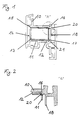
- FIG. 1 schematically shows a hollow plastic profile 10 with several cavities and inserted metal insert 11.
- the plastic hollow profile 10 is in this Embodiment as a frame profile for a window sash shown.
- the outside of the plastic wooden profile 10, which is burdened by the wind pressure, is the wall 14.
- the wall 14 is stiffened in the central cavity 12 inserted a metal insert 11.
- the metal insert 11 has a closed, rectangular hollow profile on.
- the metal insert lies with a side surface 13 11 flat on a contact surface 15 of the wall 14.
- the wall 14 is stiffened via this contact surface 15.
- the cross-sectional area of the metal insert 11 is in their height and width are slightly smaller designed as the cross-sectional area of the cavity 12.
- a projection 16 and 17 are arranged along the corner areas of a cavity wall 18, which lies opposite the wall 14 to be stiffened.
- the two protrusions 16 and 17 designed as rigid webs.
- the lead 16 and 17 protrude with their subsections 20 and 21 into the area of the cavity 12, which is provided for the metal insert 11.
- FIG. 2 shows the corner area of the cavity 12, in which the projection 16 is arranged is. It is also schematically the section 20 of the Projection 16 shown, when inserting the Metal insert 11 was removed in the cavity 12. In this embodiment, the metal insert is 11 only over the contact surface 15 and the two Projections 16 and 17 on the hollow plastic profile 10 on.
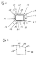
- FIG. 3 shows another embodiment of a Plastic hollow profile 30 with projections 16 and 17 shown.
- the cross-sectional profile shown is as Profile suitable for a window frame.
- This hollow plastic profile which the elements correspond to the example described in FIGS. 1 and 2, are provided with the same reference numerals.
- the metal insert with 11 additional contact points the hollow plastic profile 30.
- the side walls 25 and 26 of the cavity 12 which is vertical to the Contact surface 15 are arranged, there are more Projections 27 and 28. These side webs 27 and 28 run like the support webs 16 and 17 in the longitudinal direction of the hollow plastic profile 30, but have a smaller one Cross-sectional area.
- the side webs 27 and 28 serve the respective side walls 25 and 26 to support against the metal insert 11 in some areas. A greater power transmission through this lateral projections 27 and 28 is not provided.
- the lateral projections 27 and 28 also only protrude slightly into the cavity 12. So be the tips of these lateral projections 27 and 28 at Pushing the metal insert 11 in hardly or at all not abraded or just kinked.
- Fig.4. is the front area of the metal insert 11 shown in cross-sectional view in the embodiments 1 to 3 is used.
- the protruding side surface 13 faces for easier Insert a chamfer on the front edge 23.
- the metal insert 11 By leading the protruding side surface 13 the metal insert 11 is centered in the cavity 12, and it also ensures that the side surface 13 rests on the contact surface 15.
- the Front edge 24 of the recessed side surface 22 of the metal insert 11 has a sharp edge, the for cutting off or scraping off the protruding parts serve, which protrude into the area of the cavity, which is provided for the metal insert 11.
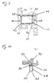
- FIG. 5 shows a cross-sectional view of an exemplary embodiment a hollow plastic profile 40 with spring elements and inserted Metal insert 41.
- the hollow plastic profile shown 40 is like the exemplary embodiment in FIG. 1 designed as a frame profile for window sashes.
- the outside a wall 44 represents the wind loaded Frame side of the window sash.
- the wall 44 serves also to delimit a central cavity 42, in which the metal insert 41 is inserted.
- the Metal insert 41 is a hollow profile with a rectangular, closed one Cross sectional area. A side surface 43 of the metal insert 41 lies flat on a contact surface 45 of the cavity wall 44. This will make the Cavity wall 44 stiffened flat.
- the cavity 12 is essentially rectangular Cross-section that is designed slightly larger is than the rectangular cross section of the metal insert
- the cavity 42 is through the cavity wall 48 the contact surface 45 is opposite, and by two Side walls 55 and 56 limited.
- two spring elements 46 and 47 are arranged.
- the two spring elements 46 and 47 are there not attached directly to cavity wall 48. These are each to achieve a better spring force on the side walls 55 and 56 at a short distance attached and extending from the cavity wall 43 along the cavity wall 48.
- In this embodiment become the spring elements 46 and 47 as part of the plastic cavity profile 40 with this in Extrusion process manufactured.
- the spring elements 46 and 47 when inserting the metal insert 41 elastically deformed and towards the cavity wall 48 pressed.
- the spring elements so tensioned 46 and 47 practice on the metal insert 41 Spring force from the metal insert 41 on the contact surface 45 presses. This way one becomes special good stiffening of the cavity wall 44 is achieved.
- the structure of the spring element 46 is in Fig. 6 in shown an enlarged detail view. From this is can be seen that the spring element 46 is an L-shaped Has cross-sectional area. The long leg of the L-shaped Cross-sectional area is in the area of the cavity wall 48 arranged on the side wall 55. The free end of the shorter leg of the L-shaped Cross-sectional profile is with the metal insert 41 in Contact and exercises on them through the elastic deformation generated spring force. In this embodiment of the plastic hollow profile 40 that comes Spring element 46 is not in contact with the cavity wall 48. The spring element 46 has in the area of Connection point between the longer cross-sectional leg and the sidewall 55 has a notch 59 on. This notch 59 provides a cross-sectional taper represents and serves as a "target" spring position. By design the notch 59 and the leg geometry can Spring characteristics of the spring element 46 influenced become.
- FIG. 7 is another embodiment of a Plastic hollow profile 60 shown with spring element.
- the hollow plastic profile 60 can, like the profile according to Fig. 3 as a frame element for window frames be used.
- the arrangement and function of the two spring elements 46 and 47 are analogous to that Embodiment according to FIGS. 5 and 6.
- the inserted Metal insert 41 comes in this embodiment also with protrusions 57 and 58 along of side walls 55 and 56 of cavity 42 in Contact. These protrusions 57 and 58 are with the protrusions 27 and 28 of the embodiment according to Fig. 3 comparable.
- the projections 57 and 58 serve the guidance of the metal insert 41 during insertion into the cavity 42 and the area-by-area support of side walls 55 and 56.
- a metal insert 41 which in the exemplary embodiments 5 to 7 is used, is in Fig. 8 shown in a sectional partial view.
- the side surface 43 of the metal insert 41 which with the contact surface 45 of the cavity wall 44 to be stiffened comes to face the opposite Side surface 52 of the metal insert 41 in front.
- the protruding side surface 43 becomes the metal insert 41 reliably arranged on the contact surface 45 and centered.
- the Front edge 53 of the side surface 43 on the front side 49 chamfered.
- the front edge 54 of the metal insert 41 the spring elements when inserting the metal insert 41 46 and 47 compresses and tensions, points also a rounded chamfer. This ensures that in this embodiment, no unwanted Abrasion on the spring elements 46 and 47 arise.
- FIG. 9 is an embodiment of an Plastic hollow profile 70 with metal insert 11 in cross-sectional view shown, which is essentially is identical to the embodiment of FIG. 5.
- the spring elements in this plastic hollow profile 70 46 and 47 a larger cross-sectional area on.
- FIG. 10 the detail according to FIG. 9 is enlarged shown. From this it can be seen that the spring element 46 maximum in this embodiment is deflected. Despite this maximum deflection a part 50 of the spring element 46 projects into the area of the cavity 42 into it, which is used for the metal insert 11 is provided. This spring element section 50 is in 10 is shown schematically. When inserting the Metal insert 11 in the cavity 42, this part 50 of the spring element 46 removed.
- the metal insert 11 has a sharp edge on the face of the surface area that corresponds to the Spring elements 46 and 47 come into contact.
- the hollow plastic profile 70 are the advantages a non-positive and a positive arrangement of the metal insert 11 in the cavity 42 combined. Due to the abutment of the spring elements 46 and 47 on the cavity wall 48, the two behave Spring elements 46 and 47 under load Hollow plastic profile 70 like rigid projections. Will the Contact surface 45 is not loaded from the outside, so practice Spring elements 46 and 47 on the metal insert 11 a continuous strength. Through this spring force the metal insert 11 is pressed onto the contact surface 45, thereby fixing the position of the metal insert 11 in the cavity 42 takes place.
Landscapes
- Engineering & Computer Science (AREA)
- Civil Engineering (AREA)
- Structural Engineering (AREA)
- Wing Frames And Configurations (AREA)
- Injection Moulding Of Plastics Or The Like (AREA)
- Specific Sealing Or Ventilating Devices For Doors And Windows (AREA)
- Diaphragms For Electromechanical Transducers (AREA)
- Pens And Brushes (AREA)
- Reinforced Plastic Materials (AREA)
- Compositions Of Macromolecular Compounds (AREA)
- Door And Window Frames Mounted To Openings (AREA)
Applications Claiming Priority (2)
| Application Number | Priority Date | Filing Date | Title |
|---|---|---|---|
| DE4322829A DE4322829C1 (de) | 1993-07-08 | 1993-07-08 | Kunststoffhohlprofil, insbesondere für Fenster- oder Türrahmen |
| DE4322829 | 1993-07-08 |
Publications (4)
| Publication Number | Publication Date |
|---|---|
| EP0633383A2 EP0633383A2 (de) | 1995-01-11 |
| EP0633383A3 EP0633383A3 (de) | 1995-08-30 |
| EP0633383B1 EP0633383B1 (de) | 1998-09-09 |
| EP0633383B2 true EP0633383B2 (de) | 2003-04-16 |
Family
ID=6492301
Family Applications (1)
| Application Number | Title | Priority Date | Filing Date |
|---|---|---|---|
| EP94110207A Expired - Lifetime EP0633383B2 (de) | 1993-07-08 | 1994-06-30 | Kunststoffhohlprofil, insbesondere für Fenster- oder Türrahmen |
Country Status (5)
| Country | Link |
|---|---|
| EP (1) | EP0633383B2 (da) |
| AT (1) | ATE170947T1 (da) |
| DE (3) | DE4322829C1 (da) |
| DK (1) | DK0633383T3 (da) |
| ES (1) | ES2122097T3 (da) |
Families Citing this family (15)
| Publication number | Priority date | Publication date | Assignee | Title |
|---|---|---|---|---|
| US5651223A (en) * | 1995-08-31 | 1997-07-29 | Chelsea Building Products | Door frame |
| DE19717318A1 (de) * | 1997-04-24 | 1998-11-05 | Reckendrees Gmbh Rolladen Und | Blend- und/oder Flügelrahmen für Fenster oder Türen (II) |
| DE19717319A1 (de) * | 1997-04-24 | 1998-11-05 | Reckendrees Gmbh Rolladen Und | Blend- und/oder Flügelrahmen für Fenster oder Türen (I) |
| DE19848767A1 (de) * | 1998-10-22 | 2000-04-27 | Pitscheider Karl | Einlage für Hohlprofile |
| FR2793438A1 (fr) | 1999-05-11 | 2000-11-17 | Rhodia Engineering Plastics Sa | Article manufacture rigide comportant un renfort thermoplastique allege |
| US6318036B1 (en) * | 1999-11-12 | 2001-11-20 | Dayton Technologies, L.L.C. | Patio door assembly with extruded plastics components |
| AU1257900A (en) * | 1999-11-18 | 2001-05-30 | Ming Zhang | Steel-plastic laminating profile and the manufacturing process thereof |
| GB0029594D0 (en) * | 2000-12-02 | 2001-01-17 | Wordsworth Jonathan J | Maintenance-free frame |
| DE202005004379U1 (de) * | 2005-03-16 | 2005-05-25 | Rehau Ag + Co. | Verstärktes Hohlkammerprofil |
| DE202008008070U1 (de) * | 2008-06-18 | 2009-10-29 | Rehau Ag + Co | Lamellen-Hohlkammerprofil für einen Klappladen |
| DE102008040296B4 (de) * | 2008-07-09 | 2018-07-05 | Sapa As | Pfosten für eine Pfosten-Riegel- oder Elementkonstruktion, Verfahren zu dessen Herstellung und Pfosten-Riegel- oder Elementkonstruktion, die einen Pfosten aufweist |
| GB0814416D0 (en) * | 2008-08-06 | 2008-09-10 | Epwin Group Ltd | Reinforcement for window and door structures |
| DE202011052460U1 (de) * | 2011-12-23 | 2013-03-25 | Rehau Ag + Co | Hohlprofil für einen Rahmen |
| CN105240678A (zh) * | 2015-09-09 | 2016-01-13 | 申科谱自动化科技(珠海)有限公司 | 一种异型材 |
| CN109654365A (zh) * | 2018-12-19 | 2019-04-19 | 苏州灵猴机器人有限公司 | 一种高强度横梁用铝型材 |
Family Cites Families (17)
| Publication number | Priority date | Publication date | Assignee | Title |
|---|---|---|---|---|
| GB1052500A (da) * | 1963-03-29 | |||
| DE1916538U (de) * | 1964-10-27 | 1965-05-26 | Willy Aurin | Fernsehbrille. |
| DE1303927C2 (de) * | 1965-12-23 | 1980-10-09 | Anschutz, Otto, 5470 Andernach | Einteiliger hohlprofilstab aus kunststoff fuer fensterrahmen mit einem in seinem geschlossenen hohlraum angeordneten versteifungsrohr |
| DE1956389U (de) * | 1966-12-02 | 1967-03-02 | Franz Lamprecht | Tragseil. |
| DE2401155B2 (de) * | 1974-01-10 | 1977-04-21 | VoIz, Georg, 6095 Ginsheim-Gustavsburg | Kunststoffprofilstab fuer fensterrahmen o.dgl. |
| DE2432746C3 (de) * | 1974-07-08 | 1980-08-21 | Bruegmann Frisoplast Gmbh, 4600 Dortmund | Fenster aus Kunststoff |
| DE3004212A1 (de) * | 1980-02-06 | 1981-08-13 | Fulguritwerke Seelze und Eichriede in Luthe bei Hannover Adolf Oesterheld GmbH & Co KG, 3050 Wunstorf | Profil fuer fenster oder tueren |
| DE8113747U1 (de) * | 1981-05-09 | 1982-01-21 | Röhm GmbH, 6100 Darmstadt | "koextrudiertes lichtdurchlaessiges kunststoffprofil" |
| DE3129567A1 (de) * | 1981-07-27 | 1983-02-10 | Heinz Pasche | Verfahren zur herstellung von hart-kunststoffprofilen mit einem durch einschieben einzubringenden metallrohr und durch dieses verfahren hergestellten kunststoffprofil |
| DE8127509U1 (de) * | 1981-09-19 | 1982-02-11 | Ruhrkohle Ag, 4300 Essen | "holzverblendete kunststoff-fensterrahmen" |
| DE3138435A1 (de) * | 1981-09-26 | 1983-04-14 | Fa. Schüt-Duis, 2960 Aurich | Verstaerkungsprofil fuer kunststoff-fensterrahmen |
| DE3172248D1 (en) * | 1981-10-19 | 1985-10-17 | Karlstadter Fenster Elementbau | Metal section for reinforcing plastics hollow sections, plastics hollow sections reinforced by such a metal section and a frame which is made of a plastics hollow section thus reinforced |
| DE8137470U1 (de) * | 1981-12-23 | 1982-07-15 | Dynamit Nobel Ag, 5210 Troisdorf | Verbundfenster |
| DE3306335A1 (de) * | 1983-02-23 | 1984-08-23 | Karlstadter Fenster- und Elementebau GmbH & Co KG, 8782 Karlstadt | Durch ein metallprofil verstaerktes kunststoffhohlprofil und rahmen |
| GB2153889B (en) * | 1984-02-10 | 1987-04-08 | Adeptal Systems Ltd | Door and window frames |
| DE3405388C1 (de) * | 1984-02-15 | 1985-09-12 | SKS-Stakusit-Stahl-Kunststoff GmbH, 4100 Duisburg | Verfahren für die Herstellung eines Hohlprofils aus thermoplastischem Kunststoff für Fenster- oder Türrahmen |
| DE3532593A1 (de) * | 1985-09-12 | 1987-03-12 | Koemmerling Kunststoff | Extrudierter kunststoffhohlprofilstab fuer rahmen von fenstern und tueren |
-
1993
- 1993-07-08 DE DE4322829A patent/DE4322829C1/de not_active Expired - Lifetime
- 1993-09-07 DE DE4330273A patent/DE4330273C1/de not_active Expired - Lifetime
-
1994
- 1994-06-30 EP EP94110207A patent/EP0633383B2/de not_active Expired - Lifetime
- 1994-06-30 AT AT94110207T patent/ATE170947T1/de not_active IP Right Cessation
- 1994-06-30 DK DK94110207T patent/DK0633383T3/da active
- 1994-06-30 ES ES94110207T patent/ES2122097T3/es not_active Expired - Lifetime
- 1994-06-30 DE DE59406867T patent/DE59406867D1/de not_active Expired - Fee Related
Also Published As
| Publication number | Publication date |
|---|---|
| DE4330273C1 (de) | 1995-02-23 |
| EP0633383B1 (de) | 1998-09-09 |
| ES2122097T3 (es) | 1998-12-16 |
| ATE170947T1 (de) | 1998-09-15 |
| DK0633383T3 (da) | 1999-06-07 |
| DE59406867D1 (de) | 1998-10-15 |
| EP0633383A3 (de) | 1995-08-30 |
| DE4322829C1 (de) | 1995-02-09 |
| EP0633383A2 (de) | 1995-01-11 |
Similar Documents
| Publication | Publication Date | Title |
|---|---|---|
| EP0633383B2 (de) | Kunststoffhohlprofil, insbesondere für Fenster- oder Türrahmen | |
| EP0843062B1 (de) | Halteelement für Fensterbeschlag | |
| EP0136431A2 (de) | Konstruktion aus Profilstäben | |
| EP0117308B1 (de) | Durch ein Metallprofil verstärktes Kunststoffhohlprofil und Rahmen | |
| EP0616107A1 (de) | Stossverbindung | |
| EP0202510B2 (de) | Blend- oder Flügelrahmen für Fenster oder Türen | |
| DE29610652U1 (de) | Verstärkungsprofil für Kunststoff-Hohlprofile zur Herstellung von Fenster, Türen o.dgl. | |
| EP0215456A1 (de) | Extrudierter Kunststoffhohlprofilstab für Rahmen von Fenstern und Türen | |
| DE69606211T2 (de) | Verbundprofile und ihr Zusammenbau für hochisolierte und holzverkleidete Tür- und Fensterrahmen | |
| DE2715238A1 (de) | Fenster- oder tuerrahmen | |
| DE29620153U1 (de) | Verbindung für winklig aneinanderstoßende Hohlprofilstäbe | |
| EP1144882B1 (de) | Linearbewegungsführung | |
| DE3343538A1 (de) | Lamellenfenster | |
| EP0111185B1 (de) | Rahmen, insbesondere für eine Duschtrennwand | |
| DE29900650U1 (de) | Dichtungsanordnung für Fenster und Türen | |
| DE3145375C2 (de) | Mehrteiliges Rahmenprofil | |
| CH640299A5 (en) | Composite profile, in particular for window frames or door frames | |
| DE102022117776B3 (de) | Dichtungselement mit entwässerungsmittel | |
| DE102022117931A1 (de) | Profilanordnung mit wärmedämmung | |
| DE19855966A1 (de) | Träger für Fensterrahmen, Fassaden oder dergleichen | |
| DE4339685C2 (de) | Fensterlaufschienenanordnung mit elastischem Dichtprofil | |
| DE29502101U1 (de) | Verbindung von flächigen, miteinander fluchtenden Planteilen | |
| DE8900041U1 (de) | Klotz zum Festsetzen von Glasscheiben o.dgl. in Tür- oder Fensterrahmen | |
| DE102008047642A1 (de) | Tür | |
| DE3200078A1 (de) | Verbindung zwischen einem ersten und einem zweiten teil |
Legal Events
| Date | Code | Title | Description |
|---|---|---|---|
| PUAI | Public reference made under article 153(3) epc to a published international application that has entered the european phase |
Free format text: ORIGINAL CODE: 0009012 |
|
| AK | Designated contracting states |
Kind code of ref document: A2 Designated state(s): AT BE CH DE DK ES FR GB IT LI LU NL PT SE |
|
| 17P | Request for examination filed |
Effective date: 19950516 |
|
| PUAL | Search report despatched |
Free format text: ORIGINAL CODE: 0009013 |
|
| AK | Designated contracting states |
Kind code of ref document: A3 Designated state(s): AT BE CH DE DK ES FR GB IT LI LU NL PT SE |
|
| 17Q | First examination report despatched |
Effective date: 19970514 |
|
| GRAG | Despatch of communication of intention to grant |
Free format text: ORIGINAL CODE: EPIDOS AGRA |
|
| GRAG | Despatch of communication of intention to grant |
Free format text: ORIGINAL CODE: EPIDOS AGRA |
|
| GRAH | Despatch of communication of intention to grant a patent |
Free format text: ORIGINAL CODE: EPIDOS IGRA |
|
| GRAH | Despatch of communication of intention to grant a patent |
Free format text: ORIGINAL CODE: EPIDOS IGRA |
|
| GRAA | (expected) grant |
Free format text: ORIGINAL CODE: 0009210 |
|
| AK | Designated contracting states |
Kind code of ref document: B1 Designated state(s): AT BE CH DE DK ES FR GB IT LI LU NL PT SE |
|
| PG25 | Lapsed in a contracting state [announced via postgrant information from national office to epo] |
Ref country code: FR Free format text: LAPSE BECAUSE OF NON-PAYMENT OF DUE FEES Effective date: 19980909 |
|
| REF | Corresponds to: |
Ref document number: 170947 Country of ref document: AT Date of ref document: 19980915 Kind code of ref document: T |
|
| REG | Reference to a national code |
Ref country code: CH Ref legal event code: EP |
|
| REG | Reference to a national code |
Ref country code: CH Ref legal event code: NV Representative=s name: BUECHEL & PARTNER AG PATENTBUERO |
|
| REF | Corresponds to: |
Ref document number: 59406867 Country of ref document: DE Date of ref document: 19981015 |
|
| GBT | Gb: translation of ep patent filed (gb section 77(6)(a)/1977) |
Effective date: 19981019 |
|
| ET | Fr: translation filed | ||
| PG25 | Lapsed in a contracting state [announced via postgrant information from national office to epo] |
Ref country code: SE Free format text: LAPSE BECAUSE OF FAILURE TO SUBMIT A TRANSLATION OF THE DESCRIPTION OR TO PAY THE FEE WITHIN THE PRESCRIBED TIME-LIMIT Effective date: 19981209 |
|
| PG25 | Lapsed in a contracting state [announced via postgrant information from national office to epo] |
Ref country code: PT Free format text: LAPSE BECAUSE OF FAILURE TO SUBMIT A TRANSLATION OF THE DESCRIPTION OR TO PAY THE FEE WITHIN THE PRESCRIBED TIME-LIMIT Effective date: 19981214 |
|
| REG | Reference to a national code |
Ref country code: ES Ref legal event code: FG2A Ref document number: 2122097 Country of ref document: ES Kind code of ref document: T3 |
|
| PGFP | Annual fee paid to national office [announced via postgrant information from national office to epo] |
Ref country code: ES Payment date: 19990607 Year of fee payment: 6 |
|
| REG | Reference to a national code |
Ref country code: DK Ref legal event code: T3 |
|
| PLBQ | Unpublished change to opponent data |
Free format text: ORIGINAL CODE: EPIDOS OPPO |
|
| PLBI | Opposition filed |
Free format text: ORIGINAL CODE: 0009260 |
|
| PG25 | Lapsed in a contracting state [announced via postgrant information from national office to epo] |
Ref country code: LU Free format text: LAPSE BECAUSE OF NON-PAYMENT OF DUE FEES Effective date: 19990630 |
|
| PLBF | Reply of patent proprietor to notice(s) of opposition |
Free format text: ORIGINAL CODE: EPIDOS OBSO |
|
| 26 | Opposition filed |
Opponent name: SCHUECO INTERNATIONAL KG Effective date: 19990608 |
|
| PLBF | Reply of patent proprietor to notice(s) of opposition |
Free format text: ORIGINAL CODE: EPIDOS OBSO |
|
| PGFP | Annual fee paid to national office [announced via postgrant information from national office to epo] |
Ref country code: BE Payment date: 20000526 Year of fee payment: 7 |
|
| PGFP | Annual fee paid to national office [announced via postgrant information from national office to epo] |
Ref country code: AT Payment date: 20000619 Year of fee payment: 7 |
|
| PGFP | Annual fee paid to national office [announced via postgrant information from national office to epo] |
Ref country code: DK Payment date: 20000626 Year of fee payment: 7 |
|
| PGFP | Annual fee paid to national office [announced via postgrant information from national office to epo] |
Ref country code: GB Payment date: 20000628 Year of fee payment: 7 |
|
| PGFP | Annual fee paid to national office [announced via postgrant information from national office to epo] |
Ref country code: NL Payment date: 20000629 Year of fee payment: 7 Ref country code: FR Payment date: 20000629 Year of fee payment: 7 |
|
| PGFP | Annual fee paid to national office [announced via postgrant information from national office to epo] |
Ref country code: CH Payment date: 20000630 Year of fee payment: 7 |
|
| PG25 | Lapsed in a contracting state [announced via postgrant information from national office to epo] |
Ref country code: ES Free format text: THE PATENT HAS BEEN ANNULLED BY A DECISION OF A NATIONAL AUTHORITY Effective date: 20000701 |
|
| PG25 | Lapsed in a contracting state [announced via postgrant information from national office to epo] |
Ref country code: LI Free format text: LAPSE BECAUSE OF NON-PAYMENT OF DUE FEES Effective date: 20010630 Ref country code: GB Free format text: LAPSE BECAUSE OF NON-PAYMENT OF DUE FEES Effective date: 20010630 Ref country code: DK Free format text: LAPSE BECAUSE OF NON-PAYMENT OF DUE FEES Effective date: 20010630 Ref country code: CH Free format text: LAPSE BECAUSE OF NON-PAYMENT OF DUE FEES Effective date: 20010630 Ref country code: BE Free format text: LAPSE BECAUSE OF NON-PAYMENT OF DUE FEES Effective date: 20010630 Ref country code: AT Free format text: LAPSE BECAUSE OF NON-PAYMENT OF DUE FEES Effective date: 20010630 |
|
| BERE | Be: lapsed |
Owner name: PAX G.M.B.H. Effective date: 20010630 |
|
| PG25 | Lapsed in a contracting state [announced via postgrant information from national office to epo] |
Ref country code: NL Free format text: LAPSE BECAUSE OF NON-PAYMENT OF DUE FEES Effective date: 20020101 |
|
| REG | Reference to a national code |
Ref country code: CH Ref legal event code: PL |
|
| GBPC | Gb: european patent ceased through non-payment of renewal fee |
Effective date: 20010630 |
|
| REG | Reference to a national code |
Ref country code: DK Ref legal event code: EBP |
|
| NLV4 | Nl: lapsed or anulled due to non-payment of the annual fee |
Effective date: 20020101 |
|
| REG | Reference to a national code |
Ref country code: ES Ref legal event code: FD2A Effective date: 20020304 |
|
| PLAW | Interlocutory decision in opposition |
Free format text: ORIGINAL CODE: EPIDOS IDOP |
|
| PLAW | Interlocutory decision in opposition |
Free format text: ORIGINAL CODE: EPIDOS IDOP |
|
| PUAH | Patent maintained in amended form |
Free format text: ORIGINAL CODE: 0009272 |
|
| STAA | Information on the status of an ep patent application or granted ep patent |
Free format text: STATUS: PATENT MAINTAINED AS AMENDED |
|
| 27A | Patent maintained in amended form |
Effective date: 20030416 |
|
| AK | Designated contracting states |
Designated state(s): AT BE CH DE DK ES FR GB IT LI LU NL PT SE |
|
| EN | Fr: translation not filed | ||
| PG25 | Lapsed in a contracting state [announced via postgrant information from national office to epo] |
Ref country code: IT Free format text: LAPSE BECAUSE OF NON-PAYMENT OF DUE FEES;WARNING: LAPSES OF ITALIAN PATENTS WITH EFFECTIVE DATE BEFORE 2007 MAY HAVE OCCURRED AT ANY TIME BEFORE 2007. THE CORRECT EFFECTIVE DATE MAY BE DIFFERENT FROM THE ONE RECORDED. Effective date: 20050630 |
|
| PLAB | Opposition data, opponent's data or that of the opponent's representative modified |
Free format text: ORIGINAL CODE: 0009299OPPO |
|
| PG25 | Lapsed in a contracting state [announced via postgrant information from national office to epo] |
Ref country code: DE Free format text: LAPSE BECAUSE OF NON-PAYMENT OF DUE FEES Effective date: 20090101 |
|
| PGFP | Annual fee paid to national office [announced via postgrant information from national office to epo] |
Ref country code: DE Payment date: 20070628 Year of fee payment: 14 |