EP0630748B2 - Tintenstrahlaufzeichnungskopf - Google Patents
Tintenstrahlaufzeichnungskopf Download PDFInfo
- Publication number
- EP0630748B2 EP0630748B2 EP94107492A EP94107492A EP0630748B2 EP 0630748 B2 EP0630748 B2 EP 0630748B2 EP 94107492 A EP94107492 A EP 94107492A EP 94107492 A EP94107492 A EP 94107492A EP 0630748 B2 EP0630748 B2 EP 0630748B2
- Authority
- EP
- European Patent Office
- Prior art keywords
- support plate
- piezoelectric
- ink jet
- base
- ink
- Prior art date
- Legal status (The legal status is an assumption and is not a legal conclusion. Google has not performed a legal analysis and makes no representation as to the accuracy of the status listed.)
- Expired - Lifetime
Links
Images


Classifications
-
- B—PERFORMING OPERATIONS; TRANSPORTING
- B41—PRINTING; LINING MACHINES; TYPEWRITERS; STAMPS
- B41J—TYPEWRITERS; SELECTIVE PRINTING MECHANISMS, i.e. MECHANISMS PRINTING OTHERWISE THAN FROM A FORME; CORRECTION OF TYPOGRAPHICAL ERRORS
- B41J2/00—Typewriters or selective printing mechanisms characterised by the printing or marking process for which they are designed
- B41J2/005—Typewriters or selective printing mechanisms characterised by the printing or marking process for which they are designed characterised by bringing liquid or particles selectively into contact with a printing material
- B41J2/01—Ink jet
- B41J2/135—Nozzles
- B41J2/14—Structure thereof only for on-demand ink jet heads
- B41J2/14201—Structure of print heads with piezoelectric elements
- B41J2/14274—Structure of print heads with piezoelectric elements of stacked structure type, deformed by compression/extension and disposed on a diaphragm
-
- B—PERFORMING OPERATIONS; TRANSPORTING
- B41—PRINTING; LINING MACHINES; TYPEWRITERS; STAMPS
- B41J—TYPEWRITERS; SELECTIVE PRINTING MECHANISMS, i.e. MECHANISMS PRINTING OTHERWISE THAN FROM A FORME; CORRECTION OF TYPOGRAPHICAL ERRORS
- B41J2/00—Typewriters or selective printing mechanisms characterised by the printing or marking process for which they are designed
- B41J2/005—Typewriters or selective printing mechanisms characterised by the printing or marking process for which they are designed characterised by bringing liquid or particles selectively into contact with a printing material
- B41J2/01—Ink jet
- B41J2/135—Nozzles
- B41J2/14—Structure thereof only for on-demand ink jet heads
- B41J2002/14387—Front shooter
Definitions
- This invention relates to an ink jet recording head.
- An ink jet recording head using piezoelectric vibrators having a nozzle plate formed with nozzle openings, a spacer for separating a pressure generation chamber, an ink supply port, a reservoir, and a vibration plate deformed by the piezoelectric vibrators to expand or shrink the pressure generation chamber is well known.
- the piezoelectric vibrators are oscillated based on a print signal to shrink or expand the pressure generation chamber, and thereby suck ink into the pressure generation chamber and eject ink drops therefrom consecutively (see e.g. EP-A-0 443 628).
- the area where piezoelectric vibrators abut a vibration plate can be made extremely small by using piezoelectric vibrators in a vertical vibration mode formed by laminating electrode material and piezoelectric material, with such a construction, a recording head having a resolution of 180 dpi or more can be provided.
- a piezoelectric vibrator unit having piezoelectric vibrators each being, for example, 5 mm long, 70 ⁇ m wide, and 0.5 mm thick disposed on a piezoelectric vibrator support plate with a 0.14-mm pitch is used in such a high resolution recording head.
- a piezoelectric vibration plate formed by laminating alternate layers of piezoelectric material and electrode material and sintering them is formed with electrodes on one surface and cut like strips with a dicing saw, a wire saw, or the like with a predetermined pitch, such as 0.14 mm, with one end of the electrode face fixed to a base in a cantilever fashion.
- the cut depth must extend at least to the piezoelectric vibrator support plate.
- material having excellent cutting properties such as glass or piezoelectric material, is used for the piezoelectric vibrator support plate to avoid added resistance to cutting when the piezoelectric vibration plate is cut, thereby preventing the piezoelectric vibrators from being broken or imperfectly formed.
- the invention provides an ink jet recording head where piezoelectric vibrators expand or shrink a pressure generation chamber to generate ink drops, and more particularly a structure of a piezoelectric vibrator unit of such an ink jet recording head.
- an ink jet recording head for ejecting ink drops by expanding or shrinking a pressure generation chamber of an ink flow route forming member consisting of nozzle openings, the pressure generation chamber, an ink supply port, and a reservoir.
- the piezoelectric vibrators are disposed and fixed in a row with a predetermined pitch to a piezoelectric vibrator support plate having an excellent cutting properties and the piezoelectric vibrator support plate is fixed to base made of material having a rigidity which is larger than the support plate.
- the cut depth of a cutter is held within the range of material having excellent cutting properties and if the piezoelectric vibrator support plate is subjected to a reaction force when ink is ejected, the base absorbs the reaction force for suppressing displacement of the contiguous piezoelectric vibrators.
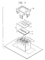
- Figure 1 illustrates one embodiment of an ink jet recording head according to the invention, wherein nozzle plate 1 has nozzle openings 2 pierced therein with a predetermined pitch so as to provide 180 dpi resolution, for example.
- Spacer 4 is sandwiched between the nozzle plate 1 and a vibration plate 5 and formed with holes to define at least one pressure generation chamber, reservoir, and ink supply port connecting them so that the holes are communicated with the nozzle openings 1.
- the spacer 4, the nozzle plate 1, and the vibration plate 5 are bonded and integrated into an ink flow route forming member 6.
- Piezoelectric vibrator units 7 are inserted into vibrator unit housing hole 9 of an outer case 8 so that free ends of the piezoelectric vibrator units abut the vibration plate 5 of the ink flow route forming member. All these components are unified by a frame 10 to constitute an ink jet recording head.
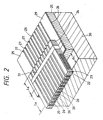
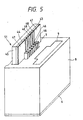
- FIG. 2 illustrates the piezoelectric vibrator unit 7 of this embodiment.
- Piezoelectric vibrators 20 each formed by laminating alternate layers of piezoelectric material layers 22 and electrode layers 23, 24 and having an active area LA whose tip side only is expanded or shrunk, i.e., oscillated, and an inactive area LB which does not contribute to vibration.
- the inactive areas LB of the piezoelectric vibrators 20 are fixed with an adhesive to a thin film electrode layer 26 formed on the surface of a vibrator support plate 25.
- the vibrator support plate 25 has slits 27 formed therein through the electrode layer 26 to the vibrator support plate 25 with the same pitch as the piezoelectric vibrators 20, when the piezoelectric vibration plate is cut for dividing the electrode layer 26 into drive electrodes 28, and common electrodes 29.
- Numeral 30 is a base fixed to the other surface of the vibrator support plate 25 with an adhesive. The length of the base 30 is selected so that the tip side of the vibrators 20 project therefrom by a length ⁇ L.
- Numeral 31 is a common electrode junction member which is connected to electrodes formed on the surface of the piezoelectric vibrators 20 and has ends connected to the common electrodes 29 of the vibrator support plate 25.
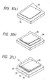
- Figures 3(a)-(c) illustrates a manufacturing method of the piezoelectric vibration plate.
- a so-called "green sheet” 34 formed by fixing a clay-like piezoelectric vibration material on the surface of a substrate 33 as shown in Fig. 3(a) and an electrode layer 35 used as one pole is formed on the surface of the green sheet 34 as shown in Fig. 3(b).
- a green sheet 37 is laminated so as to fill in the level difference between the electrode layer 35 and the green sheet 34 and an electrode layer 38 used as the other pole is formed on the surface of the green sheet 37, as shown in Fig. 3(c). These steps are repeated until the desired number of layers are formed. After the green sheets 34 and 37 are dried to a predetermined degree, they are sintered while pressure is applied thereto, thereby providing a piezoelectric vibration plate having a predetermined thickness and a predetermined number of layers.
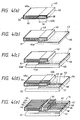
- An electrode layer 41 is formed on a front end face 40a and the back of a piezoelectric vibration plate 40 thus provided and electrode layers 35 are connected in parallel.
- An electrode layer 42 is formed on rear end face 40b and portion which becomes an inactive area LB on the surface and the electrodes 38 of piezoelectric vibrator 40 are electrically connected in parallel, as shown in Figure 4(a).
- the electrode layer 41 which will be cut into drive electrodes is fixed to a vibrator support board 44, made of a material having excellent cutting properties, such as piezoelectric material, glass, or the like similar to the material of piezoelectric vibrators, having an electrode layer 43 on the surface with a conductive adhesive, as shown in Fig. 4(b).
- a material which is higher in rigidity than the piezoelectric vibrator support plate 44 such as carbon jig steel, stainless steel, soft iron, or zinc diecast material
- the base 45 is mounted on the bed of a cutting device such as dicing saw or wire saw and cutting is started with a predetermined pitch, for example, 140 ⁇ m from the front end face 40a to rear end face 40b of the piezoelectric vibration plate 40.
- a predetermined pitch for example, 140 ⁇ m from the front end face 40a to rear end face 40b of the piezoelectric vibration plate 40.
- the cutter contacts the support plate 44.
- the vibrator support plate 44 is made of a material having excellent cutting properties, i.e. cutting resistance similar to that of the piezoelectric material, the cutter continues the cutting operation in substantially the same load state as when cutting the piezoelectric vibration plate 40 only.
- the piezoelectric vibration plate 40 is cut into piezoelectric vibrators 46 of predetermined size and the electrode layer 43 is separated into common electrodes 47 and drive electrodes 48 by slits 49, as shown in Fig. 4(d).
- the piezoelectric vibration plate 40 is separated into the desired number of piezoelectric vibrators 46 and the electrode layer 43 is separated by slits 49 corresponding to the piezoelectric vibrators 46.
- the surface of the electrode layer 42 is connected by a common electrode conjunction member 50 and both ends are fixed to the common electrodes 47 of piezoelectric vibrator support plate 44 while their conductive relationship is maintained, thereby providing a vibrator unit 51 fixed to the base 45.
- the piezoelectric vibrator 46 When the piezoelectric vibrator 46 is expanded or shrunk, particularly to eject an ink drop, it is subjected to a large reaction force caused by a pressure load of the pressure generation chamber 52. However, it can sufficiently resist the reaction force caused by the pressure load of the pressure generation chamber 52 because the base 45 is made of a highly rigid material and is fixed to vibrator support plate 44 and further the front end 45a of the base 45 projects by a distance ⁇ L beyond the front end 44a of the vibrator support plate 44 (see Fig. 2).
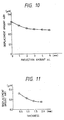
- a base 45 made of stainless steel having a given thickness, for example, 1.5 mm was used and, as shown in Figure 9, a unit having the front end face 45a of the base 45 which does not extend beyond the front end face 44a of the piezoelectric vibrator support plate 44 was compared to a unit having the front end face 45a projecting from the front end face 44a of the piezoelectric vibrator support plate 44.
- the thickness of the base 45 was varied and the displacement amount ⁇ R1 of the piezoelectric vibrator 46-1 to which the drive signal was not applied was examined as described above. As shown in Figure 11, as the base 45 thickens, the displacement amount ⁇ R1 decreases, but becomes substantially constant where the thickness is 1.5 mm or more.
- the base 45 made of highly rigid material provides an extremely effective device for preventing crosstalk or ink mist from occurring and that more effective means is provided by projecting the front face of the base 45 from the piezoelectric vibrator support plate 44 and thickening the base 45. Further, if the vibrator support plate 44 is thinned to about the piezoelectric vibrator disposition pitch, for example, about 0.15 mm, the displacement amount ⁇ R1 can be suppressed without hindering cutting of the piezoelectric vibration plate to the piezoelectric vibrators.
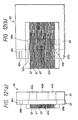
- Figures 12(a) and 12(b) shows a second preferred embodiment of piezoelectric vibrator unit, wherein numeral 60 is a piezoelectric vibrator support plate made of a ceramic board having cutting properties. The center portion is cut away to provide a recess 60a and projections 60b and 60c are formed on both sides of the support plate 60, one projection 60c having a positioning recess 60d formed therein. Piezoelectric vibrators 61, formed by cutting a piezoelectric vibration plate are fixed at a given pitch on the surface, as in the first embodiment.
- Numeral 62 is a base. Front end face 62a of the portion thereof opposed to the piezoelectric vibrators 61, 61, 61... projects toward the side of the piezoelectric vibrators 61 more than front end face 60e of the piezoelectric vibrator support plate 60, and a second projection 62b projects further towards the front end and is formed at the center of base 62.
- the base 62 is bonded to the piezoelectric vibrator support plate 60.
- the recess 60d of the piezoelectric vibrator support plate 60 is positioned by engagement with a projection (not shown) of outer case 8 and the tip of each piezoelectric vibrator 61 abuts pressure generation chamber 52 at predetermined precision simply by dropping the vibrator unit 65 into a vibrator unit housing hole 9 of the outer case 8.
- the base 62 made of highly rigid material projects toward the side of the piezoelectric vibrators 61 to a greater degree than the piezoelectric vibrator support plate 60 at least in the area opposed to the piezoelectric vibrators 61, and thus can resist reaction forces generated by ejection ink.
- the second projection 62b is formed on the base 62 and reinforced selectively, thereby furthermore securely preventing ink mist or crosstalk from occurring while maintaining a device which is light in weight.
- FIG. 13 shows a third preferred embodiment of piezoelectric vibrator unit of ink jet recording head used with the invention.
- a piezoelectric vibrator support plate 70 is made comparatively thick with material having excellent cutting properties.
- a piezoelectric vibration plate is bonded to the surface of the piezoelectric vibrator support plate 70 and is cut to define piezoelectric vibrators 71 as described above.
- the base 72 is made of highly rigid material having thickness to provide a given gap ⁇ G between the base and the piezoelectric vibrators and is fixed to the front end of the piezoelectric vibrator support plate 70 with an adhesive.
- Numeral 73 indicates a junction electrode member.
- the piezoelectric vibrator support plate 70 in the area supporting the piezoelectric vibrator 71 receiving reaction force from a pressure generation chamber when an ink drop is spouted tends to be displaced, but distortion is suppressed to a minimum because of rigidity of the base 72. This prevents ink mist or crosstalk from occurring through nozzle openings.
- the base 72 made of material having a comparatively large density can be formed to a minimum size to prevent the piezoelectric vibrator support plate 70 from being distorted and maintain a light weight device. Even if the piezoelectric vibrator support plate 70 has a sufficient thickness fitted for cutting, the gap ⁇ G between the base 72 and the piezoelectric vibrators 71 can be set to the minimum for preventing ink mist or crosstalk from occurring.
- the piezoelectric vibrators 71, 71 supported only by the piezoelectric vibrator support plate 70.
- a base 80 formed with a stepped level difference portion 80a to provide a gap ⁇ G between the base and piezoelectric vibrators 71 on the rear side are used and the front of piezoelectric vibrator support plate 70 can be made to abut a vertical wall 80b of the level difference portion 80a for bonding, as shown in Figure 14.
- the piezoelectric vibration plate and the piezoelectric vibrator support plate are separate members in these embodiments.
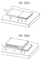
- as many layers of green sheets 90 of piezoelectric material as required are laminated on a substrate 91 so as to provide an appropriate thickness as a piezoelectric vibrator support plate after sintering (see Fig. 15(a)) and a piezoelectric vibration plate manufacturing process similar to that as shown in Figure 3 may be repeated on the surface (see Fig. 15(b)) to form a piezoelectric vibration plate 92.
- Numeral 93 is a temporary base used for filling the gap due to the level difference until completion of the sintering. According to this embodiment, bonding of the piezoelectric vibration plate and piezoelectric vibrator support plate is made unnecessary and rigidity can also be raised because there is no adhesive layer.
- the above-identified embodiments relate to a recording head of a so-called "face eject” type provided by laminating the nozzle plate, spacer, and vibration plate as an example.
- a similar effect can be produced if the invention is applied to a spacer for forming a recording head of a so-called “edge eject” type with the substrate, spacer, and vibration plate laminated and nozzle openings pierced on the end face in the length direction of pressure generation chambers.
- an ink jet recording head for ejecting ink drops by expanding or shrinking a pressure generation chamber of an ink flow route forming member consisting of nozzle openings, the pressure generation chamber, an ink supply port, and a reservoir.
- Piezoelectric vibrators are used in a vertical vibration mode. The piezoelectric vibrators are disposed and fixed in a row with a predetermined pitch, to a piezoelectric vibrator support plate having excellent cutting properties and the piezoelectric vibrator support plate is fixed to a base made of a material having a larger rigidity than the support plate.
- the piezoelectric vibrator support plate is subjected to reaction force when ink is ejected, the base resists the force.
- undesired displacement of the contiguous piezoelectric vibrators can be suppressed to prevent ink mist or crosstalk from occurring and the outer case can be made of polymeric material having a low rigidity to allow a recording head to be light in weight.
Landscapes
- Particle Formation And Scattering Control In Inkjet Printers (AREA)
Claims (12)
- Tintenstrahlaufzeichnungskopf zum Ausstoß von Tintentröpfchen durch Ausdehnen oder Schrumpfen einer Druckerzeugungskammer (52) eines Tintenflußroutenbildungselements (6), wobei der Tintenstrahlaufzeichnungskopf folgendes aufweist:piezoelektrische Vibratoren (7,46,61,71) in einem Vertikalvibrationsmodus, die in einer Reihe mit einem vorbestimmten Abstand an einer Trägerplatte (25,44,60,70) piezoelektrischer Vibratoren angeordnet und befestigt sind, wobei die Trägerplatte aus einem Material gebildet ist, welches eine Festigkeit gegenüber Schneiden durch eine Trennvorrichtung aufweist, die jener entspricht, die zum Schneiden der piezoelektrischen Vibratoren verwendet wird; undeine Basis (30,45,62,72,80), die aus einem Material hergestellt ist, welches eine Steifheit aufweist, welche größer als jene der Trägerplatte ist, wobei die Basis an der Trägerplatte befestigt ist,wobei die piezoelektrischen Vibratoren an der Trägerplatte mit einem Klebemittel befestigt sind.
- Tintenstrahlaufzeichnungskopf zum Ausstoß von Tintentröpfchen durch Ausdehnen oder Schrumpfen einer Druckerzeugungskammer (52) eines Tintenflußroutenbildungselements (6), wobei der Tintenstrahlaufzeichnungskopf folgendes aufweist:piezoelektrische Vibratoren (7,46,61,71) in einem Vertikalvibrationsmodus, die in einer Reihe mit einem vorbestimmten Abstand an einer Trägerplatte (25,44,60,70) piezoelektrischer Vibratoren angeordnet und befestigt sind, wobei die Trägerplatte aus einem Material gebildet ist, welches eine Festigkeit gegenüber Schneiden durch eine Trennvorrichtung aufweist, die jener entspricht, die zum Schneiden der piezoelektrischen Vibratoren verwendet wird; undeine Basis (30,45,62,72,80), die aus einem Material hergestellt ist, welches eine Steifheit aufweist, welche größer als jene der Trägerplatte ist, wobei die Basis an der Trägerplatte befestigt ist,wobei inaktive Bereiche (LB) der piezoelektrischen Vibratoren an der Trägerplatte befestigt sind.
- Tintenstrahlaufzeichnungskopf zum Ausstoß von Tintentröpfchen durch Ausdehnen oder Schrumpfen einer Druckerzeugungskammer (52) eines Tintenflußroutenbildungselements (6), wobei der Tintenstrahlaufzeichnungskopf folgendes aufweist:piezoelektrische Vibratoren (7,46,61,71) in einem Vertikalvibrationsmodus, die in einer Reihe mit einem vorbestimmten Abstand an einer Trägerplatte (25,44,60,70) piezoelektrischer Vibratoren angeordnet und befestigt sind, wobei die Trägerplatte aus einem Material gebildet ist, welches eine Festigkeit gegenüber Schneiden durch eine Trennvorrichtung aufweist, die jener entspricht, die zum Schneiden der piezoelektrischen Vibratoren verwendet wird; undeine Basis (30,45,62,72,80), die aus einem Material hergestellt ist, welches eine Steifheit aufweist, welche größer als jene der Trägerplatte ist, wobei die Basis an der Trägerplatte befestigt ist,wobei die Trägerplatte Schlitze (27) aufweist, die darin durch eine darüberliegende Elektrodenschicht (26) in die Trägerplatte (25) ausgebildet sind.
- Tintenstrahlaufzeichnungskopf gemäß Anspruch 2 oder 3, wobei die Trägerplatte integral mit den piezoelektrischen Vibratoren gesintert ist.
- Tintenstrahlaufzeichnungskopf gemäß einem der Ansprüche 1 bis 4, wobei das Tintenflussroutenbildungselement (6) Düsenöffnungen (2), die Druckerzeugungskammer (52), einen Tintenzufuhrdurchlaß (54) und ein Reservoir (53) darin ausgebildet aufweist.
- Tintenstrahlaufzeichnungskopf gemäß einem der Ansprüche 1 bis 5, wobei eine Vorderendseite (45a) der Basis (45) über ein Vorderende der Trägerplatte (44) vorsteht.
- Tintenstrahlaufzeichnungskopf gemäß einem der vorhergehenden Ansprüche, wobei die Basis (62) über die Trägerplatte (60) an einem mittleren Bereich der Reihe der piezoelektrischen Vibratoren (61) vorsteht.
- Tintenstrahlaufzeichnungskopf gemäß einem der vorhergehenden Ansprüche, wobei die Basis (72) an dem Vorderende der Trägerplatte (70) befestigt ist.
- Tintenstrahlaufzeichnungskopf gemäß einem der Ansprüche 1 bis 7, wobei die Basis (80) einen gestuften Höhenunterschiedsbereich (80a) aufweist und die Trägerplatte (70) ein Vorderende anstoßend an eine Wandfläche (80a), definiert durch den Höhenunterschiedsbereich (80a), aufweist.
- Tintenstrahlaufzeichnungskopf gemäß einem der vorhergehenden Ansprüche, wobei die Trägerplatte aus einem Material ausgewählt aus Glas und einem piezoelektrischen Material hergestellt ist.
- Tintenstrahlaufzeichnungskopf gemäß einem der vorhergehenden Ansprüche, wobei die Basis aus einem Material ausgewählt aus Werkzeugstahl, rostfreiem Stahl, Weicheisen und Zinkdruckgußmaterial hergestellt ist.
- Tintenstrahlaufzeichnungskopf gemäß einem der vorhergehenden Ansprüche, wobei die Trägerplatte durch Laminieren piezoelektrischer Materialien und Sintern derselben gebildet ist.
Applications Claiming Priority (9)
| Application Number | Priority Date | Filing Date | Title |
|---|---|---|---|
| JP11034293 | 1993-05-12 | ||
| JP11034393 | 1993-05-12 | ||
| JP110343/93 | 1993-05-12 | ||
| JP110342/93 | 1993-05-12 | ||
| JP11034393 | 1993-05-12 | ||
| JP11034293 | 1993-05-12 | ||
| JP12057994 | 1994-05-09 | ||
| JP120579/94 | 1994-05-09 | ||
| JP06120579A JP3109017B2 (ja) | 1993-05-12 | 1994-05-09 | インクジェット式記録ヘッド |
Publications (4)
| Publication Number | Publication Date |
|---|---|
| EP0630748A2 EP0630748A2 (de) | 1994-12-28 |
| EP0630748A3 EP0630748A3 (de) | 1997-11-05 |
| EP0630748B1 EP0630748B1 (de) | 1999-12-15 |
| EP0630748B2 true EP0630748B2 (de) | 2007-02-14 |
Family
ID=27311709
Family Applications (1)
| Application Number | Title | Priority Date | Filing Date |
|---|---|---|---|
| EP94107492A Expired - Lifetime EP0630748B2 (de) | 1993-05-12 | 1994-05-13 | Tintenstrahlaufzeichnungskopf |
Country Status (5)
| Country | Link |
|---|---|
| US (1) | US5548314A (de) |
| EP (1) | EP0630748B2 (de) |
| JP (1) | JP3109017B2 (de) |
| DE (1) | DE69422090T3 (de) |
| SG (1) | SG46315A1 (de) |
Families Citing this family (16)
| Publication number | Priority date | Publication date | Assignee | Title |
|---|---|---|---|---|
| JP3422342B2 (ja) * | 1994-03-28 | 2003-06-30 | セイコーエプソン株式会社 | インクジェツト式記録ヘツド |
| JPH07329292A (ja) * | 1994-04-13 | 1995-12-19 | Seiko Epson Corp | インクジェット式記録ヘッド |
| JPH08187848A (ja) * | 1995-01-12 | 1996-07-23 | Brother Ind Ltd | 積層式圧電素子およびその製造方法 |
| JPH08192513A (ja) * | 1995-01-18 | 1996-07-30 | Fujitsu Ltd | 圧電式インクジェットプリンタヘッド |
| JPH08279631A (ja) * | 1995-04-05 | 1996-10-22 | Brother Ind Ltd | 積層型圧電素子の製造方法 |
| JP3697850B2 (ja) * | 1997-09-04 | 2005-09-21 | セイコーエプソン株式会社 | 液体噴射記録ヘッド及びその製造方法 |
| US6417600B2 (en) * | 1998-09-17 | 2002-07-09 | Seiko Epson Corporation | Piezoelectric vibrator unit, method for manufacturing the same, and ink jet recording head comprising the same |
| US6578953B2 (en) * | 1999-03-29 | 2003-06-17 | Seiko Epson Corporation | Inkjet recording head, piezoelectric vibration element unit used for the recording head, and method of manufacturing the piezoelectric vibration element unit |
| EP1113509A3 (de) * | 1999-12-27 | 2005-03-23 | Seiko Epson Corporation | Piezoelektrischer Vibrator, Flüssigkeitsstrahlkopf sowie zugehörige Herstellungsverfahren |
| EP1364793B1 (de) * | 2001-03-01 | 2009-07-15 | Ngk Insulators, Ltd. | Kammförmiges, piezoelektrisches stellglied und herstellungsverfahren dafür |
| US7077511B2 (en) * | 2002-08-26 | 2006-07-18 | Ricoh Printing Systems Ltd. | Housing used in inkjet head |
| JP4035827B2 (ja) | 2002-10-03 | 2008-01-23 | セイコーエプソン株式会社 | 液体噴射装置 |
| JP4145760B2 (ja) | 2002-10-03 | 2008-09-03 | セイコーエプソン株式会社 | 圧電アクチュエータユニット及びその製造方法 |
| JP2007320187A (ja) * | 2006-06-01 | 2007-12-13 | Toshiba Tec Corp | インクジェットヘッドの製造方法およびインクジェットヘッド |
| JP2008183803A (ja) * | 2007-01-30 | 2008-08-14 | Brother Ind Ltd | 液滴噴射装置 |
| US8608291B2 (en) | 2011-07-27 | 2013-12-17 | Funai Electric Co., Ltd. | Piezoelectric inkjet printheads and methods for monolithically forming the same |
Citations (2)
| Publication number | Priority date | Publication date | Assignee | Title |
|---|---|---|---|---|
| JPS6090770A (ja) † | 1983-10-25 | 1985-05-21 | Seiko Epson Corp | インクジェットヘッド |
| US5128694A (en) † | 1989-06-09 | 1992-07-07 | Sharp Kabushiki Kaisha | Head for ink-jet printer |
Family Cites Families (5)
| Publication number | Priority date | Publication date | Assignee | Title |
|---|---|---|---|---|
| US4788557A (en) * | 1987-03-09 | 1988-11-29 | Dataproducts Corporation | Ink jet method and apparatus for reducing cross talk |
| JP3041952B2 (ja) * | 1990-02-23 | 2000-05-15 | セイコーエプソン株式会社 | インクジェット式記録ヘッド、圧電振動体、及びこれらの製造方法 |
| JPH0584907A (ja) * | 1991-09-26 | 1993-04-06 | Seiko Epson Corp | インクジエツト式印字ヘツド |
| US5510816A (en) * | 1991-11-07 | 1996-04-23 | Seiko Epson Corporation | Method and apparatus for driving ink jet recording head |
| JP3116984B2 (ja) * | 1992-06-22 | 2000-12-11 | セイコーエプソン株式会社 | インクジェットヘッド |
-
1994
- 1994-05-09 JP JP06120579A patent/JP3109017B2/ja not_active Expired - Fee Related
- 1994-05-12 US US08/241,974 patent/US5548314A/en not_active Expired - Lifetime
- 1994-05-13 EP EP94107492A patent/EP0630748B2/de not_active Expired - Lifetime
- 1994-05-13 DE DE69422090T patent/DE69422090T3/de not_active Expired - Lifetime
- 1994-05-13 SG SG1996002763A patent/SG46315A1/en unknown
Patent Citations (2)
| Publication number | Priority date | Publication date | Assignee | Title |
|---|---|---|---|---|
| JPS6090770A (ja) † | 1983-10-25 | 1985-05-21 | Seiko Epson Corp | インクジェットヘッド |
| US5128694A (en) † | 1989-06-09 | 1992-07-07 | Sharp Kabushiki Kaisha | Head for ink-jet printer |
Also Published As
| Publication number | Publication date |
|---|---|
| JP3109017B2 (ja) | 2000-11-13 |
| EP0630748A3 (de) | 1997-11-05 |
| JPH07132597A (ja) | 1995-05-23 |
| DE69422090D1 (de) | 2000-01-20 |
| EP0630748B1 (de) | 1999-12-15 |
| US5548314A (en) | 1996-08-20 |
| SG46315A1 (en) | 1998-02-20 |
| DE69422090T2 (de) | 2000-07-13 |
| DE69422090T3 (de) | 2007-05-31 |
| EP0630748A2 (de) | 1994-12-28 |
Similar Documents
| Publication | Publication Date | Title |
|---|---|---|
| EP0630748B2 (de) | Tintenstrahlaufzeichnungskopf | |
| US6394363B1 (en) | Liquid projection apparatus | |
| EP1208983B1 (de) | Auf Abruf arbeitender Tintenstrahldruckkopf | |
| EP0671271B1 (de) | Tintenstrahlaufzeichnungsgerät | |
| EP0628413B1 (de) | Tintenstrahlkopf | |
| JP4467860B2 (ja) | 小滴堆積装置 | |
| EP0867289A1 (de) | Tintenstrahlaufzeichnungsgerät | |
| US20010002136A1 (en) | Drop-on-demand ink-jet printing head | |
| US20070002092A1 (en) | Liquid discharge head and recording device | |
| US5543009A (en) | Method of manufacturing a sidewall actuator array for an ink jet printhead | |
| JPH05229116A (ja) | インクジェットヘッド | |
| JPH04241949A (ja) | インクジェットヘッド | |
| JP2004160941A (ja) | 液滴噴射ヘッド、インクジェット記録装置 | |
| JPH04148934A (ja) | インクジェットヘッド | |
| JP3385840B2 (ja) | インクジェットヘッド | |
| JPH05318730A (ja) | インクジェットヘッド | |
| JP3473034B2 (ja) | インクジェット記録ヘッド | |
| JPH0781058A (ja) | 積層pztアレイの固定方法 | |
| JPH06143564A (ja) | インクジェットヘッド | |
| JPH07156377A (ja) | インクジェット式印字ヘッド及びその製造方法 | |
| JP2006312271A (ja) | インクジェットヘッド及びその製造方法 | |
| JPH11348274A (ja) | インクジェット記録ヘッド | |
| JP2003072064A (ja) | インクジェット記録ヘッド | |
| JP2003127395A (ja) | インクジェット記録ヘッド | |
| JPH10109416A (ja) | インクジェット式記録ヘッド用圧電振動子ユニット、及びその製造方法 |
Legal Events
| Date | Code | Title | Description |
|---|---|---|---|
| PUAI | Public reference made under article 153(3) epc to a published international application that has entered the european phase |
Free format text: ORIGINAL CODE: 0009012 |
|
| AK | Designated contracting states |
Kind code of ref document: A2 Designated state(s): CH DE FR GB IT LI NL SE |
|
| PUAL | Search report despatched |
Free format text: ORIGINAL CODE: 0009013 |
|
| AK | Designated contracting states |
Kind code of ref document: A3 Designated state(s): CH DE FR GB IT LI NL SE |
|
| 17P | Request for examination filed |
Effective date: 19980115 |
|
| GRAG | Despatch of communication of intention to grant |
Free format text: ORIGINAL CODE: EPIDOS AGRA |
|
| 17Q | First examination report despatched |
Effective date: 19990209 |
|
| GRAG | Despatch of communication of intention to grant |
Free format text: ORIGINAL CODE: EPIDOS AGRA |
|
| GRAH | Despatch of communication of intention to grant a patent |
Free format text: ORIGINAL CODE: EPIDOS IGRA |
|
| GRAH | Despatch of communication of intention to grant a patent |
Free format text: ORIGINAL CODE: EPIDOS IGRA |
|
| GRAA | (expected) grant |
Free format text: ORIGINAL CODE: 0009210 |
|
| AK | Designated contracting states |
Kind code of ref document: B1 Designated state(s): CH DE FR GB IT LI NL SE |
|
| REG | Reference to a national code |
Ref country code: CH Ref legal event code: EP |
|
| ITF | It: translation for a ep patent filed |
Owner name: BUZZI, NOTARO&ANTONIELLI D'OULX |
|
| REF | Corresponds to: |
Ref document number: 69422090 Country of ref document: DE Date of ref document: 20000120 |
|
| REG | Reference to a national code |
Ref country code: CH Ref legal event code: NV Representative=s name: BOVARD AG PATENTANWAELTE |
|
| ET | Fr: translation filed | ||
| PLBQ | Unpublished change to opponent data |
Free format text: ORIGINAL CODE: EPIDOS OPPO |
|
| PLBI | Opposition filed |
Free format text: ORIGINAL CODE: 0009260 |
|
| PLBF | Reply of patent proprietor to notice(s) of opposition |
Free format text: ORIGINAL CODE: EPIDOS OBSO |
|
| 26 | Opposition filed |
Opponent name: OCE-TECHNOLOGIES B.V. Effective date: 20000915 |
|
| NLR1 | Nl: opposition has been filed with the epo |
Opponent name: OCE-TECHNOLOGIES B.V. |
|
| PLBF | Reply of patent proprietor to notice(s) of opposition |
Free format text: ORIGINAL CODE: EPIDOS OBSO |
|
| REG | Reference to a national code |
Ref country code: GB Ref legal event code: IF02 |
|
| PLCK | Communication despatched that opposition was rejected |
Free format text: ORIGINAL CODE: EPIDOSNREJ1 |
|
| APBP | Date of receipt of notice of appeal recorded |
Free format text: ORIGINAL CODE: EPIDOSNNOA2O |
|
| APBQ | Date of receipt of statement of grounds of appeal recorded |
Free format text: ORIGINAL CODE: EPIDOSNNOA3O |
|
| APAA | Appeal reference recorded |
Free format text: ORIGINAL CODE: EPIDOS REFN |
|
| APBU | Appeal procedure closed |
Free format text: ORIGINAL CODE: EPIDOSNNOA9O |
|
| APAH | Appeal reference modified |
Free format text: ORIGINAL CODE: EPIDOSCREFNO |
|
| PLAB | Opposition data, opponent's data or that of the opponent's representative modified |
Free format text: ORIGINAL CODE: 0009299OPPO |
|
| R26 | Opposition filed (corrected) |
Opponent name: OCE-TECHNOLOGIES B.V. Effective date: 20000915 |
|
| NLR1 | Nl: opposition has been filed with the epo |
Opponent name: OCE-TECHNOLOGIES B.V. |
|
| PUAH | Patent maintained in amended form |
Free format text: ORIGINAL CODE: 0009272 |
|
| STAA | Information on the status of an ep patent application or granted ep patent |
Free format text: STATUS: PATENT MAINTAINED AS AMENDED |
|
| 27A | Patent maintained in amended form |
Effective date: 20070214 |
|
| AK | Designated contracting states |
Kind code of ref document: B2 Designated state(s): CH DE FR GB IT LI NL SE |
|
| REG | Reference to a national code |
Ref country code: CH Ref legal event code: AEN Free format text: AUFRECHTERHALTUNG DES PATENTES IN GEAENDERTER FORM |
|
| NLR2 | Nl: decision of opposition |
Effective date: 20070214 |
|
| PGFP | Annual fee paid to national office [announced via postgrant information from national office to epo] |
Ref country code: SE Payment date: 20070508 Year of fee payment: 14 |
|
| PGFP | Annual fee paid to national office [announced via postgrant information from national office to epo] |
Ref country code: CH Payment date: 20070516 Year of fee payment: 14 |
|
| REG | Reference to a national code |
Ref country code: SE Ref legal event code: RPEO |
|
| NLR3 | Nl: receipt of modified translations in the netherlands language after an opposition procedure | ||
| ET3 | Fr: translation filed ** decision concerning opposition | ||
| REG | Reference to a national code |
Ref country code: CH Ref legal event code: PL |
|
| PG25 | Lapsed in a contracting state [announced via postgrant information from national office to epo] |
Ref country code: LI Free format text: LAPSE BECAUSE OF NON-PAYMENT OF DUE FEES Effective date: 20080531 Ref country code: CH Free format text: LAPSE BECAUSE OF NON-PAYMENT OF DUE FEES Effective date: 20080531 |
|
| PG25 | Lapsed in a contracting state [announced via postgrant information from national office to epo] |
Ref country code: SE Free format text: LAPSE BECAUSE OF NON-PAYMENT OF DUE FEES Effective date: 20080514 |
|
| PGFP | Annual fee paid to national office [announced via postgrant information from national office to epo] |
Ref country code: FR Payment date: 20110523 Year of fee payment: 18 |
|
| PGFP | Annual fee paid to national office [announced via postgrant information from national office to epo] |
Ref country code: GB Payment date: 20110511 Year of fee payment: 18 Ref country code: NL Payment date: 20110520 Year of fee payment: 18 |
|
| PGFP | Annual fee paid to national office [announced via postgrant information from national office to epo] |
Ref country code: IT Payment date: 20110518 Year of fee payment: 18 Ref country code: DE Payment date: 20110511 Year of fee payment: 18 |
|
| REG | Reference to a national code |
Ref country code: NL Ref legal event code: V1 Effective date: 20121201 |
|
| GBPC | Gb: european patent ceased through non-payment of renewal fee |
Effective date: 20120513 |
|
| PG25 | Lapsed in a contracting state [announced via postgrant information from national office to epo] |
Ref country code: IT Free format text: LAPSE BECAUSE OF NON-PAYMENT OF DUE FEES Effective date: 20120513 |
|
| REG | Reference to a national code |
Ref country code: FR Ref legal event code: ST Effective date: 20130131 |
|
| REG | Reference to a national code |
Ref country code: DE Ref legal event code: R119 Ref document number: 69422090 Country of ref document: DE Effective date: 20121201 |
|
| PG25 | Lapsed in a contracting state [announced via postgrant information from national office to epo] |
Ref country code: NL Free format text: LAPSE BECAUSE OF NON-PAYMENT OF DUE FEES Effective date: 20121201 |
|
| PG25 | Lapsed in a contracting state [announced via postgrant information from national office to epo] |
Ref country code: GB Free format text: LAPSE BECAUSE OF NON-PAYMENT OF DUE FEES Effective date: 20120513 Ref country code: FR Free format text: LAPSE BECAUSE OF NON-PAYMENT OF DUE FEES Effective date: 20120531 |
|
| PG25 | Lapsed in a contracting state [announced via postgrant information from national office to epo] |
Ref country code: DE Free format text: LAPSE BECAUSE OF NON-PAYMENT OF DUE FEES Effective date: 20121201 |